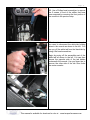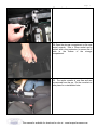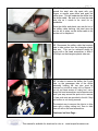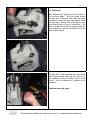
1
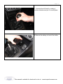
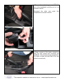
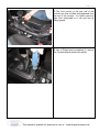
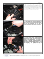
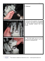
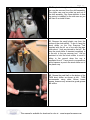
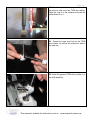
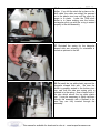
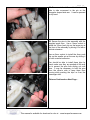
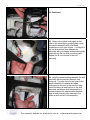
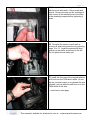
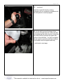
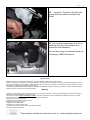
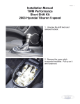
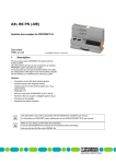
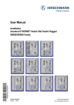
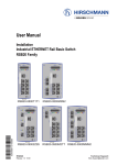
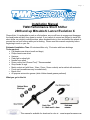
Page 1
Installation Manual
TWM Performance Short Shifter
2008 and up Mitsubishi Lancer Evolution X
Please Note: It is preferable to park on a flat surface, as you will have to engage and disengage
the hand brake and shift from gears to neutral. If you cannot do so and are obliged to install the
short shifter on a slightly inclined surface, place wooden blocks in front and behind the wheels to
prevent the car from moving while you’re working. Please read this manual completely before
beginning to work on your car.
Estimated Installation Time: 60 minutes shifter only, 75 minutes with base bushings
Tools required:
• Flat head screw drivers (small and large)
• Philips head screw driver
• Hammer
• Flash light or shop light
• Needle nose pliers
• Rotary cutting tool (Dremel Tool) **Recommended
• Shop towels or rags
• Metric socket set (with 8mm, 10mm, 12mm, 14mm sockets) and a ratchet with extension
• Punch set (screwdrivers may be substituted)
• Bench Vise
• All purpose automotive grease (white Lithium based grease preferred)
What you get in this kit:
This manual is available for download in color at : www.twmperformance.com
Page 2
1. Unscrew the shift knob by rotating it
counter-clockwise and put it in a safe place.
2. Remove the ashtray in front of the shifter.
This manual is available for download in color at : www.twmperformance.com
Page 3
3. Remove the small storage compartment in
front of the handbrake by pulling up on it as
pictured to the left.
Disconnect the white wire under
compartment as shown to the left.
this
4. Begin removal of the center console by
lifting the rear portion that surrounds the
handbrake. Be sure the storage compartment
lid is open to allow the back half of the rear
portion to move freely.
This manual is available for download in color at : www.twmperformance.com
Page 4
5. The front portion of the rear half of the
console can now be lifted and separated from
the rest of the console. It is held in place by
clips from underneath so it will pop free by
lifting upward.
6. Use a Philips head screwdriver to remove
the 2 screws directly behind the shifter.
This manual is available for download in color at : www.twmperformance.com
Page 5
7. The front portion of the console with the
shift boot attached can now be lifted, however
it cannot be removed from the car yet as there
is a clip holding a wire at the front which must
be removed as shown in the next step.
8. Use needle nose pliers to compress the
tabs on the clip at the front part of this section.
With the tabs depressed, the clip can be
pushed through and out from the under side.
9. Turn this portion of the console over and
disconnect the plastic plug for the lighter by
pulling on the plastic portion. Do not pull on
the wires. There are no tabs to depress on
this clip, the connector simply slides off. The
front portion of the console can now be
removed from the car and put in a safe place.
This manual is available for download in color at : www.twmperformance.com
Page 6
10. Use a Phillips head screwdriver to remove
the 2 screws in front of the shifter that have
been exposed by removing the front portion of
the console in the previous step.
11. In order to remove the center console,
you need to disconnect the white tab holding
wires to the console as shown to the left. You
can pry off the white tab from the black tab by
using a flat head screwdriver.
Begin by prying off the accessible part of the
white tab as shown to the left. You can then
access the opposite side of the tab hidden
underneath the console. Use you finger tips to
remove the other side of the tab from under
the center console.
This manual is available for download in color at : www.twmperformance.com
Page 7
11. …continued.
12. Open the storage compartment on the rear
center console. Use a 10mm socket and a
ratchet with a long extension to remove the 2
bolts in the bottom of the storage
compartment.
13. The center console is now free and can
be removed from the car. Put the console in a
safe place for re-installation later.
This manual is available for download in color at : www.twmperformance.com
Page 8
14. Working at the bottom of the shifter itself,
spread the steel wire clip apart with your
fingers or needle nose pliers and push the
cable down. This will separate the shifter from
the shifter cable. Be sure not to lose the steel
wire clip as it needs to be used for reinstallation.
Once the shifter and plastic cup are slid out of
the shifter cable housing, the steel wire clip
can be left in place on the shifter cable to be
certain not to misplace it.
15. Disconnect the shifter cable that controls
side to side motion from the triangular plastic
side arm. This can be achieved simply by
prying with a flat head screwdriver to slide it
off the pin on the triangular plastic side arm.
16. In order to remove the shifter, the 2 push
clips on the passenger side of the shifter
assembly holding the two pins must be
removed or cut with a rotary tool or Dremel. If
you do not have access to rotary tool, use a
sharp flat head screwdriver and a hammer and
work your way around the push nut to remove
it. New push nuts are provided in the kit if they
are broken or cut during removal.
The easiest way to remove the clips is to slice
them with a rotary cutting tool, then to slide
them off with a flat head screwdriver.
Continued on Next Page…
This manual is available for download in color at : www.twmperformance.com
Page 9
16. Continued.
Both methods are pictured to the left and on
the previous page. The first image shows
removal with a hammer and sharp flat head
screwdriver, while the next two images show
removal with a Dremel tool by slicing the clips
and sliding them off with a screwdriver. Be
sure to wrap shop towels or rags around the
shift assembly to protect the interior from any
debris while cutting.
17. With the 2 clips removed and side shifter
cable disconnected, push the two pins out of
the assembly using a hammer and a small
punch. Use a screwdriver if a punch is not
available.
Continued on next page….
This manual is available for download in color at : www.twmperformance.com
Page 10
17. Continued.
18. Take note of the orientation of the spring
on the side of the shifter for re-installation
later. Both pins that go through the shifter can
now be completely removed from the
assembly.
19.
The white plastic cap can now be
removed from the shift assembly. Put it in a
safe place for re-installation later.
This manual is available for download in color at : www.twmperformance.com
Page 11
20. The plastic triangular side arm and spring
can now be removed from the shift assembly.
The shifter can now be pulled up and out of
the shift assembly. Pay close attention to how
the spring is installed on the side arm as you
will have to re-install it later.
21. Remove the small plastic cup from the
bottom of the stock shifter. To do so, hang the
stock shifter on the Cup Remover Tool
supplied with the kit on a vice with the jaws
open about 1 inch as pictured to the left. Be
sure the stock shifter is inserted completely in
to the slot in the cup remover tool. Ask an
assistant to hold the stock shifter to avoid it
falling to the ground when the cup is
separated from it. Use a punch or screwdriver
and a hammer to punch the stock shifter out of
the plastic cup.
22. Grease the small ball on the bottom of the
TWM short shifter as shown at left. TWM
recommends using white lithium based
grease, however any automotive grade grease
will suffice.
This manual is available for download in color at : www.twmperformance.com
Page 12
23. Press the small white cup you removed in
the previous step on to the TWM short shifter.
Place the cup on a flat surface and push the
shifter down in to it.
24. Grease the main pivot ball on the TWM
short shifter, as well as the small pivot ball on
the side arm.
25. Install the greased TWM short shifter in to
the shift assembly.
This manual is available for download in color at : www.twmperformance.com
Page 13
26. Re-connect the lower shifter cable to the
shifter. If you left the steel clip in place on the
shift cable, the cable can simply be pressed
on to the plastic pivot cup until the steel clip
snaps in to place. Lower the TWM short
shifter in to place making sure the bottom
rectangular pivot cup with the o-ring is seated
properly in the shift assembly.
27. Re-install the spring for the triangular
shaped side arm ensuring it’s orientation is
correct as pictured to the left.
28. Re-install the top white plastic cap and the
triangular shaped side arm. Be sure the
shifter is properly seated in the bottom pivot
cup, and that the side arm spring pivot is
inserted in to the spring. Now re-insert both of
the pins which secure the top white plastic
cap. It may be necessary to lightly tap them
through the assembly with a hammer to be
sure they are fully inserted through the
assembly.
This manual is available for download in color at : www.twmperformance.com
Page 14
29. Re-connect the shifter cable that controls
side to side movement to the pin on the
triangular shaped side arm. It can be pressed
on by hand.
30. Secure the pins in the assembly with the
supplied push clips. Use a 14mm socket to
install the 10mm push clip on the larger pin at
the front of the assembly by driving it on with a
ratchet extension.
Use an 8mm socket to install the 4mm push
clip on the smaller pin at the rear by driving it
on with a ratchet extension.
You should be able to install these clips by
hand, make sure they are pushed all the way
on to prevent the pins from sliding out over
time. It may be necessary to hold the pins
from the driver’s side to keep them from
moving while pushing the clips on from the
passenger side.
Pictures Continued on Next Page…
This manual is available for download in color at : www.twmperformance.com
Page 15
30. Continued.
31. PLEASE NOTE: The following steps are
only required if you have purchased the
optional shift assembly bushings with your
TWM short shifter. If you do not have the
base bushings, proceed to step 36.
Using a ratchet with an extension and a 12
mm socket, unbolt the four bolts securing the
assembly to the floor pan and remove the
bolts.
32. Lift the shift assembly slightly and use a
flat head screwdriver to push the steel sleeves
in the rubber bushings out through the bottom
of the bushing. Repeat for all four corners.
It may be helpful to cut the strip of carpet
which passes over the rear of the shift
assembly to free up some room to lift the
assembly.
Pictures Continued on Next Page…
This manual is available for download in color at : www.twmperformance.com
Page 16
32. Continued.
33. Remove the rubber bushings from the
base of the assembly by pushing them down
through the assembly with a flat head
screwdriver or with your fingers. It is helpful to
pull on the bushings from beneath the
assembly with your fingers while pushing them
down through the top with your other hand.
Repeat for all four corners of the shift
assembly.
34. Install the base bushings beneath the shift
assembly with the smaller diameter step
facing up. This step fits in to the holes in the
plastic assembly to replace the rubber
bushings you removed in the previous step.
Install a bushing at each corner of the shift
assembly and ensure that the assembly is
seated properly with each smaller diameter
step on each bushing fully inserted in the
holes at each corner of the assembly.
This manual is available for download in color at : www.twmperformance.com
Page 17
35. Secure the shift assembly back in place
with the stock bolts and a 12mm socket and
ratchet. Be sure the step on the bushings at
each corner of the assembly are in the holes
in the assembly properly before tightening it
down.
36. Re-install the center console and reconnect all wires and connectors by reversing
steps 10 to 13. Install the special shift boot
retainer on the shifter as pictured to the left.
Do not tighten the set screw yet.
37. Install the front part of the console with the
shift boot over the TWM short shifter. Do not
clip the console in place or re-connect the wire
beneath it yet just slide the shift boot on to the
TWM shifter at this time.
…continued on next page.
This manual is available for download in color at : www.twmperformance.com
Page 18
37. …continued.
Install the stock shift knob by rotating
clockwise until you experience resistance and
the shift pattern is correctly aligned.
38. Lift the shift boot and front part of the
console as pictured to the left. Move the shift
boot retainer up the shifter shaft so it holds the
top of the shift boot pressed up against the
bottom of the shift knob. You can now tighten
the set screw to secure the shift boot retainer
on the shifter with the supplied allen key.
…continued on next page.
This manual is available for download in color at : www.twmperformance.com
Page 19
38. …continued. Pictured to the left is the
special shift boot retainer secured to the
shifter.
39. You can now reverse steps 2 to 9 to reinstall the front part of the console and
connect the wire beneath it.
You are done, enjoy the drive and thank you
for choosing TWM Performance!
Legal Disclaimer
TWM Performance is not responsible for the misuse, incorrect installation, or failure of any product we sell.
Under no circumstances, including but not limited to negligence, will TWM Performance be liable for special or consequential damages that result
from the use or inability to use our products. TWM Performance does not assume responsibility for any damage to the user, passenger or vehicle
resulting from the operation of a TWM Performance product.
TO PROTECT USERS FROM INJURY OR DEATH. THE USER ASSUMES ALL RISKS. Autocrossing, track events, and high speed driving are all
dangerous activities - always drive responsibly and safely.
Warranty
Installation of some TWM Performance products may or may not void factory warranties. Always keep OEM equipment that has been replaced in
case work is required at the dealer or the vehicle is sold.
This warranty covers the original purchasing consumer. This warranty is limited to repair or replacement by TWM Performance of any TWM
Performance product that fails because of a defect in materials or workmanship.
Warranty does not cover the following:
-Damage incurred to related vehicle components
-Regular day to day wear on vehicle
-Shipping costs for replacements
-Installation costs and vehicle down time
-Products that have been modified, incorrectly installed or misused.
-Mounting hardware and bearings
This manual is available for download in color at : www.twmperformance.com