1
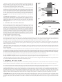
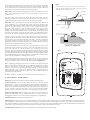
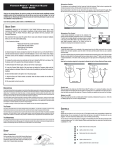
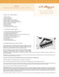
L
.
R
.
ELEMENT
B
A
ONBOARD
INSTALLATION
MANUAL
&
G
G
S
P
I
C
K
U
P
S
SYSTEM
USER'S
GUIDE
4 8 3
N .
F R O N T A G E
N I P O M O ,
C A
R D .
9 3 4 4 4
W W W . L R B A G G S . C O M
TA B L E O F CO N T E N TS
1. Package contents
2. Overview & cautions
3. Removal of previous system (retrofit only)
4. New installation woodworking
5. Strapjack installation
6. Preamp installation
7. Element installation
8. External controls
1.PACK AGE CONTENTS
one (1) Element undersaddle pickup
one (1) onboard preamp
one (1) strapjack harness
six (6) ½" black installation screws
six (6) fiber washers
one (1) flexible black preamp bezel
two (2) self-stick wire clips
one (1) preamp routing template
2.OVERVI E W
&
C AU TI ONS
The L.R. Baggs Element Onboard is an onboard retrofit system that combines the Element undersaddle pickup with an all-discrete class A batteryaccess preamp. The system is a drop-in retrofit upgrade that is designed to fit in the hole used by several factory-installed systems.
We recommend that this system be installed by a professional dealer/installer. We do not provide installation advice or support for home or
hobbyist installations. Installers: please read the instructions carefully before proceeding. We will not be responsible for any damage to the guitar
or personal injury resulting from installation, improper installation, use or misuse of the product.
Before beginning a retrofit installation, be sure that the screw holes in the preamp bezel (mounting flange) line up with the existing preamp
screw holes on the guitar.
For new installations, the preamp will generally fit in guitars with a side width of four inches or larger, assuming average lining and top thickness.
Again, verify that these requirements are met before making any alterations to the guitar.
The preamp requires a 9V battery, which is not included in this package.
Avoid unnecessary bending of the Element pickup.
Installation overview: The recommended installation procedure is to begin by removing the old system and/or performing any necessary
woodwork. Then install the strapjack and preamp. Finally, the Element should be installed and tested to ensure proper sound and string balance.
3.R E MOVAL
OF
PRE VI O US
S Y S T E M (retrofit installations only)
Remove the entire preamp, output harness and pickup. You will also need to remove the old strapjack.
Most guitar manufacturers include cross-grain reinforcement panels on solid wood guitars beneath the preamp mounting screw holes. If, upon
removing the old preamp from a solid wood guitar, you discover that there are no reinforcement strips, we recommend installing cross-grain
reinforcement shims underneath the screw holes to prevent chipping the wood on the guitar.
Once the previous system is removed, proceed to the strapjack installation (section 5).
4.N E W
I N STALL AT I ON WOO DWO RK IN G
4.1 Routing the preamp hole: Be absolutely sure that the preamp will fit inside the guitar at its intended location before making any cuts to the
instrument! Guitars with a side width of less than four inches may be unable to accommodate the preamp due to the size of the interior lining.
For solid wood guitars (especially maple), we recommend gluing two 2.5” (63.5 mm) x .5” (12.7 mm) plywood cross-grain reinforcement panels on
the inside of the guitar body where the screw holes will be drilled. This prevents the wood from splitting during the drilling process.
If you are uncomfortable freehand-cutting this area using the enclosed paper template (as described below), we recommend that you use the
paper template to fashion a hard template out of masonite, Plexiglas or another suitable material.
1. Choose a location on the side of the instrument to mount the preamp. The
flattest possible area just above the waist on the upper bout and below the
shoulder is recommended. Double-check to make sure the preamp will clear
all internal braces and other obstacles when installed.
fig. 1
2. Lay the enclosed paper template on the chosen location and secure it with
masking tape on all four edges. With a sharp scribe put a dimple in the center
of each of the screw holes and then drill out the holes using a #45 drill bit
(.082” or 2.08 mm). Cut out the area for the preamp carefully and slowly using
a rotary cutter with a sharp 1/8” cutting bit. We recommend cutting just inside
the lines for the initial cut and then cleaning up the edges with a file. Remove
the template and clean up any excess tape residue with a soft cloth and
naphtha.
4.2 Drilling the strapjack hole: For proper installation, this jack requires a
clean 1/2" hole in the tail block of the instrument. Start by placing a piece of
masking tape on the outside of the instrument over the drilling area (to avoid
chipping the finish), drill a small pilot hole in the tail block and then follow
with a step drill. Now proceed to the strapjack installation as detailed in the
following section.
5 . S TR AP JACK
smaller
threaded
section
protrudes
fig. 2
extension
I NSTAL L ATI ON
Remove the strap ring, retaining nut and one washer from the end of the jack.
There should still be one star locking washer, one flat washer and a nut
remaining on the jack. Bring the jack down through the soundhole into the
body and insert it into the pre-drilled hole in the tail block. Using the internal
nut (be sure to include the flat and star washers), set the proper depth that
will allow the entire smaller threaded section to protrude from the instrument
(see figure 1). With the jack in place, lay the remaining washer over the threads
and attach the external retaining nut until it’s tight. Finish by attaching the
strap ring (it should cover the retaining nut and washer) so as not to crack the
finish of the instrument by asserting too much pressure. Now proceed to the
preamp installation in the following section.
6 . P REA MP
tail
block
fig. 3
fig. 4
drill bit
normal saddle:
drill floor
jeweler's screwdriver
short saddle:
drill side wall
I NSTA LL ATI ON
This preamp is designed for sides that are .090” to .165” thick and reasonably flat or convex. The skirt of the bezel may bottom out on guitars that
have especially thin or concave sides. This will prevent the bezel from seating completely on the guitar’s side. If this happens, place the provided
fiber washers over the protruding ends of the screws (inside of the guitar body) to space the preamp down into the guitar.
The bezel is made of a special material that may be cold-formed by hand and can be easily made to conform to the curvature of the guitar side.
Simply bend the bezel by hand until it fits to the guitar side without any gaps. It may help to over-bend the bezel slightly in spots until it lies
flush on the guitar side's surface.
1. Once the bezel has been formed, drop it into the existing cutout and screw the 4 provided screws into the holes until they protrude into the
guitar about 1/16”. Do not enlarge the holes in the guitar! If you enlarge the holes, the screws will not be able to hold the bezel in place to
position the preamp.
2. Insert a battery into the battery compartment (observe polarity!) and push the compartment into the hole until it click-locks into place. Insert
the preamp into the guitar through the sound hole and place it into the opening in the bezel from inside of the guitar. Wiggle it until the screw
ends find the corresponding slots in the chassis. Center the preamp laterally (along the length of the side) in the bezel and start the screws into
the plastic. Hold the preamp firmly against the side so that it does not “walk” as you tighten the screws. Before you tighten the screws completely,
be sure that the battery compartment does not bind against the bezel when you open and close the compartment.
Do not overtighten the screws. This will cause the bezel ends to lift from the side. Excess overtightening may even cause the screws to cut
through the bezel. It is helpful to watch the edge of the bezel as you tighten; stop when it seats nicely against the wood.
3. Plug the strapjack wire into the preamp's right-hand socket, and secure the wire inside the guitar with the self-stick wire clip provided. Then
proceed to the Element installation instructions in the following section.
7 . E LE ME NT
I N STALL AT ION
7.1 Installation notes: For optimum performance of the Element, the bridge slot must have a clean, flat surface free of any debris or over-spray
from the finish. The slot must be a minimum of .125” (1/8”) deep, but we suggest a depth of at least .187" (3/16”) to avoid excessive saddle tilt.
The commonly-known 50/50 rule applies: The amount of saddle visible above the bridge surface (with pickup installed) should be no greater than
the amount of saddle in the slot beneath the bridge surface; otherwise the balance and output of the pickup may suffer.
7.2 Short saddle note: The first 1/8" of the Element pickup is not active. If you do not have a minimum of 1/4" of saddle beyond the hi-E string, you
may experience low output on this string. To remedy this, drill a small horizontal hole in the end of the slot to extend the pickup further under
the saddle (see figure 2). To drill this hole without disrupting the floor of the saddle slot, place a small jeweler's screwdriver under the tip of the
drill bit. On short saddles we also advise that the pickup exit hole be drilled into the end wall of the saddle slot rather than the slot's floor (see
figure 4) to likewise extend saddle/pickup contact at the exit end. Again use the jeweler's screwdriver to protect the saddle floor as you drill.
7.3 Installation: Remove the strings from the guitar. To duplicate the string height exactly, scribe a line along the front edge of the saddle where
it extends above the bridge. The line will later be used as a guide when removing material from the bottom of the saddle to compensate for the
thickness of the pickup (.037” total). Remove the saddle to drill the hole for the pickup. The drill bit needs to be as large as the saddle slot will
allow.
Inspect the inside of the guitar and note the position of the braces in relation
to the saddle slot. Drill at either end of the slot on the side that will enable
you to avoid all braces as you penetrate the top, as shown in figure 5. Blow out
the slot with compressed air and check for remaining debris.
fig. 5
This view depicts the bridge at an angle that islevel with the
guitar top and perpendicular to the saddle slot. Note the rounded
edge where the hole has been drilled.
drill bit
Important: Round the inside of the hole where it meets the bottom of the slot
with a small, sharp knife or small file to avoid pinching the pickup as the
saddle lies on it.
slot
bridge
Feed the pickup into the slot from inside the guitar with either side up.
Inserting a toothpick or similar object through the hole from the outside is
helpful in finding the location of the hole on the inside of the guitar.
Important: The fit of the saddle in the slot is the single most important factor
in this installation. It is crucial that the bottom of the slot and the lower
surface of the saddle be flat to make even contact with the pickup. The saddle
should fit loosely enough in the slot that it can be pulled out with your
fingertips. It will then have a slight forward lean when the strings are under
tension. It is absolutely necessary to compensate for this slight lean by
sanding a tilt in the bottom of the saddle so it still sits flat on the pickup when
the strings are at tension (see figure 6). If the saddle is too tight, binds at all or
is too loose, this will have a negative effect on the string balance and output.
guitar top
brace
fig. 6
Insert the saddle in the slot and note how much material must be removed to
compensate for the thickness of the pickup. Remove the saddle and sand its
bottom surface on a belt sander until the scribe line is just above the bridge
top. Finish sanding the bottom by hand. It is best to do this against a
machined flat surface with fine sandpaper. Use a straight edge with a strong
light source to inspect the flatness of your saddle.
Insert the pickup all the way into the slot, place the saddle on top of it, and
temporarily secure it with a piece of tape. Secure the wire with a wire clip as
close to the exit hole as is practical, with a one- to two-inch service loop.
Failure to secure the wire may produce boominess and feedback. Now restring
the guitar, plug the pickup wire into the preamp's left-hand socket, and plug
into your amp or PA. Confirm that the EQ controls are at their default positions
and test the Element, paying careful attention to string balance. If the sound is
satisfactory, the installation is complete. If not, read on.
proper saddle-pickup contact
(saddle lean exaggerated)
fig. 7
String balance problems are almost always the result of an uneven interface
between the bottom of the saddle and the saddle slot. If the string balance is
uneven, check these surfaces to ensure that they are both completely flat.
Tip: A segmented packaging knife blade is a useful tool in determining the
flatness of the saddle slot. Break off only enough blade segments so as much
blade fits into the slot as possible. Briefly use a back-and-forth scraping
motion to see if the slot bottom scrapes evenly. Any high or low spots will be
readily apparent. A minor low spot in the slot may be compensated for by
shims under the pickup; however, for gaps over .005" or multiple gaps, we
recommend rerouting the slot.
1
2
4
Be sure to review the controls, which are explained in the following section.
8.E X TE RN AL
CONTRO LS
3
5
Caution: Do not remove the battery from the preamp while plugged in.
1. Phase inversion: This inverts the signal phase. If you are experiencing
feedback, this is the first tool that should be used. However, depending on
your position in relation to the speaker(s), pressing this button may have no
effect or even make the problem worse. Also, phase inversion is of little use if
you are moving around the stage. There is no way to predict beforehand
whether or not you are in the correct phase setting without using this button.
2. Battery gauge light: When the battery light dims, it is time to replace the
battery. To change the battery, simply press the top of the preamp to
disengage the click-lock access. This will pop out the battery compartment.
3. Volume control: This adjusts the preamp volume.
4. Notch filter: This knob is used to cancel guitar body resonance feedback. If, after using the phase inversion, feedback persists, rotate this knob
(when the guitar is feeding back) until it cancels that frequency. This will be obvious when it happens; the filter will "grab" the problem frequency
and eliminate it. With this control properly set, you should discover that you can play significantly louder without feedback. When all else fails and
you are still not loud enough, you can turn down the bass and even increase the treble for more "cut."
5. Treble and bass controls: These controls adjust the level of high and low frequency output.