1
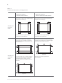
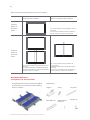
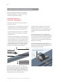
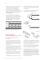
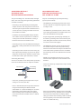
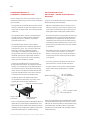
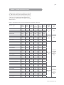
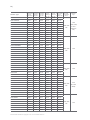
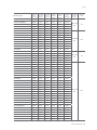
INSTALLATION
MANUAL ANNEX
OF STANDARD
SOLAR MODULE
ANNEX A: ALTERNATIVE MOUNTING METHODS
|3
ANNEX B: ALTERNATIVE GROUNDING METHODS
|10
ANNEX C: MODULE SPECIFICATION
|15
ANNEX D: MODULE CLEANING GUIDELINE
|18
AMENDED EDITIONS AND DATES
|19
EN-Rev IM/GN-AM-EN/A2 Copyright © Dec. 2014. Canadian Solar Inc.
ANNEX A: ALTERNATIVE MOUNTING METHODS
All the basic requirements of the main installation · Canadian Solar Inc. warranty may be void in cases manual should apply to the alternative mounting where improper clamps or unsuitable installation methods, unless otherwise specified.
methods are found. When installing inter-modules or end type clamps, take measures so as:
MOUNTING METHOD A
CLAMPING
Not to bend the module frame
Not to touch or cast shadow on the front glass
Not to damage the surface of the frame
To ensure the clamps overlap the module frame
· The mounting method has been qualified by
by at least 0.2 in (5 mm).
Canadian Solar Inc. and certified by VDE and CSA.
· Top or bottom clamping methods can vary and To ensure the clamps overlap length is at
least 1.57 in (40 mm).
are dependent on the mounting structures.
The installer shall follow the mounting guidelines,
Min. 3 mm thickness
recommended by the mounting system supplier.
· Each module must be securely fastened at a
minimum of 4 points on two opposite sides.
The clamps should be positioned according to the
authorized position ranges defined in table A-1.
Install and tighten the module clamps to the mounting rails using the torque stated by the mounting hardware manufacturer. M8 size bolt and nut are used for clamping method. Tightening torques should be within 10~17 Nm (7.4~12.5 ftlbs) for M8 x 1.5 coarse thread bolts, depending on
Min. overlap length
bolt class.
Min. 5 mm overlap
40 mm
· Different recommendations from specific clamping
hardware suppliers should prevail. System designer
· Clamp material should be anodized
and installer are responsible for load calculations aluminum alloy.
and for proper design of support structure.
· Floating type clamps are not authorized.
· Clamp positions are of crucial importance for the reliability of the installation, the clamp centerlines must only be positioned within the ranges indicated
in table A-1, depending on the configuration and load.
· For configurations where the mounting rails run
parallel to the clamps installation side, precautions should be taken to ensure the module frame (C-shape) overlap the rail by 0.59 in (15 mm) or
more.
www.canadiansolar.com
4 |
Table A-1:
Authorized attachments for clamping method
Uplift load ≤ 2400 Pa
Uplift load ≤ 2400 Pa
Downforce load ≤ 2400 Pa
2400 Pa ≤ Downforce load ≤ 5400 Pa
Use 4 clamps on the long side, the allowed range
depends on the module type.
Use 4 clamps on the long side, the allowed range
depends on the module type.
A1
A1
B1
B1
A1
A1
B1
B1
Clamping on
long side
frame
Mounting rails shall run perpendicularly
or parallel to the long side frame .
Mounting rails shall run perpendicularly
or parallel to the long side frame .
Use 4 clamps on the short side, the allowed
range depends on the module type. Mounting
rails shall run parallel or perpendicularly to the
short frame side.
Use 4 clamps on the short side, the allowed range
depends on the module type. An additional support
bar should be placed below the module.
A2
A2
A2
A2
A2
A2
A2
A2
Support bar
Clamping on
short side
frame
For CS5P and CS6P series, an additional support
bar should be placed below the module where
download force above 1600Pa is expected.
Mounting rails should run parallel to the short
side frame .
A2
A2
A2
A2
Support bar
EN-Rev IM/GN-AM-EN/A2 Copyright © Dec. 2014. Canadian Solar Inc.
Mounting rails should run parallel to the
short side frame .
| 5
Authorized range for clamping as a function of model type:
Model type
A1 range (mm)
B1 range (mm)
A2 range (mm)
CS5A
220 – 380
330 – 400
170 – 200
CS5AH
120 – 170
120 – 170
170 – 200
CS5P
220 – 390
330 – 400
220 – 270
CS6A
220 – 340
270 – 330
200 – 250
CS6P, CS5T
240 – 410
340 – 410
200 – 250
CS6X
340 – 550
410 – 490
200 – 250
CS6V
240 – 410
340 – 410
170 – 210
CS6VH
130 – 210
160 – 210
170 – 210
CS6K
247.5– 410
247.5– 330
200– 250
MOUNTING METHOD B
INSERTION SYSTEMS
· The mounting method has been qualified by
Canadian Solar Inc. and certified by VDE and CSA.
To ensure insertion profile thickness and
tolerance suits module thickness 1.57
in (40 mm) for most of Canadian Solar inc
· Insertion methods can vary and are dependent modules).
on the mounting structures. The installer shall
follow the mounting guidelines, recommended by
the mounting system supplier.
· Each module must be securely fixed through all its length on two opposite sides. Install and tighten the insertion profiles to the support structure using the hardware and instructions provided by the mounting system manufacturer. System
designer and installer are responsible for load
calculations and for proper design of support structure.
· Canadian Solar Inc. warranty shall be void in cases where improper insertion systems or unsuitable installation methods are found. When installing insertion profiles, take measures so as:
Not to bend the module frame
Not to touch or cast shadow on the front glass
Not to damage the surface of the frame
To ensure the insertion profiles overlap the module frame by at least 0.39 in (10 mm).
To ensure the module frame (C-shape) overlap the insertion profiles by at least 0.59 in (15
mm).
www.canadiansolar.com
6 |
Table A-2: Authorized attachments for insertion method
Uplift load ≤ 2400 Pa
Uplift load ≤ 2400 Pa
Downforce load ≤ 2400 Pa
2400 Pa ≤ Downforce load ≤ 5400 Pa
Insertion
profile on
long side
Use 2 insertion profiles running parallel to the long
side frame.
For CS6X series, installations where the downforce
load can reach up to a 5400 Pa are authorized.
frame
Insertion
profile on
short side
frame
Use 2 insertion profiles running parallel to the short
side frame.
For CS5P and CS6P series, an additional support bar
should be placed below the module where download
force above 1600 Pa is expected.
Use 2 insertion profiles running parallel to the
short side frame.
An additional support bar should be placed below
the module.
For CS6X series, installations where the downforce
load can reach up to a 5400 Pa are authorized.
MOUNTING METHOD C
Grizzly Bear® FR Gen II SYSTEM
· Grizzly Bear® FR Gen II System has been qualified Components
by Intertek (ETL) to UL2703 for use with Canadian Solar Inc. modules.
EN-Rev IM/GN-AM-EN/A2 Copyright © Dec. 2014. Canadian Solar Inc.
Support
Claw I
Long Claw
Wind Deflector
Wind Deflector
End Plate
Fastener Kit
| 7
Table A-3: Authorized attachments for Grizzly Bear® FR Gen II SYSTEM
Claw
Compatible Modules
Installation Methods
Claw I
Place a PV module face down on protected
CS5A series, , CS5T-M,
work surface and place a Claw over the
CS6P series, CS6A series,
module frame flange on the short side of
CS6X series
the module; slide to the corner and tighten
the 3/8-16 x 1.25” 18-8 hex head cap screw
Only 1600Pa is autho-
between 24.4 and 27.1 Nm (18-20 ft-lb). En-
rized for CS6P/CS6X
sure that the Claw is seated up against the
without support bar.
flanges of both the long and short sides of
the module. Each module must be fitted
with four (4) Claws.
Long Claw
This Claw is used for PV modules that are
not compatible with flange clamp style
Claws. The Long Claw attaches at the
CS6X-M, CS6X-P
module mounting holes using standard
bolting method. Refer to paragraph 6.1
for suitable torque and fastening requirements.
· Refer to Grizzly Bear® FR Gen II Installation
Manual (9910010 Rev A) from PanelClaw Inc.
for more information and always follow latest safety procedures when installing.
Failure to follow corresponding regulatory
instructions will void Canadian Solar Inc. module warranty.
www.canadiansolar.com
8 |
MOUNTING METHOD D
ATI CLAMPING
module) to maintain a balanced force with the end
module.
· The mounting method has been qualified by
· The top module edge must engage the clamp a
Canadian Solar Inc. and certified by CSA.
minimum of 0.375 in (9.5 mm) on the top clamp
edge and the bottom module edge must engage a
· Array Technology Inc. (ATI) uses a clamp mounting minimum of 0.69 in (17.5 mm) on the bottom
method for attaching modules to the tracker clamp edge. If these distances cannot be
assembly. The clamp mounting method involves measured, a total of 0.062 in (1.57 mm) of gap is
installing a module mounting clamp assembly allowed between the module and both clamps.
on the torque tube, attaching a module, and then This gap can be offset to one side or split between
another clamp assembly until the row of modules
the clamps.
is installed. Clamps may also be installed earlier, when bearing housings are installed on torque tubes.
· All the clamp assemblies, spacer plate, and hard
ware should be tightened to the torque tube with a torque setting of 18 ± 3 Nm (13 ± 2 ft-lbs), using · Canadian Solar Inc. qualified 2 kinds of ATI clamps,
the long bolts provided (bolt length is dependent 12 in (304.8mm) length standard clamp and 12
on model used).
in (304.8mm) length high-clearance clamp. Both
Top Channel
clamps are mounted on long side frame, in the
middle position (with Universal Clamp Module Jig),
so that the module is evenly divided in half by the
torque tube.
· End clamps are attached to the module at the end
of each array and in the middle next to the gear drive. Four end clamps are used for each row of
modules. End clamps are at least 22 in (558.8mm)
long and have four attachment holes. End clamps
also include a spacer plate (fabricated for each
specific module) that must be inserted in the clamp
Bottom Lip
on the outside of the clamp (opposite the end
(Wider Flange)
Module Mounting
Strap
Table A-4: Authorized attachments for ATI clamping
CS6P Series
CS6X Series
12-inch length
Uplift load ≤ 1200 Pa
Uplift load ≤ 2400 Pa
standard clamp
Downforce load ≤ 1200 Pa
Downforce load ≤ 5400 Pa
12-inch length
Uplift load ≤ 1200 Pa
Uplift load ≤ 2400 Pa
high-clearance clamp
Downforce load ≤ 3600 Pa
Downforce load ≤ 5400 Pa
· Refer to DuraTrack™HZ Solar Tracker Installation Guide (November 2012, Rev. B-01) from Array Technologies Inc. for more information and always Intermediate
follow latest safety procedures when installing.
Clamp
End
Clamp
Failure to follow corresponding regulatory
instructions will void Canadian Solar Inc. module warranty.
Torque Tube
EN-Rev IM/GN-AM-EN/A2 Copyright © Dec. 2014. Canadian Solar Inc.
UCM Jig
| 9
MOUNTING METHOD E
FOR SPECIFIC MODULE RANGES
1. Not to bend the laminate excessively
2. Not to cast shadow on the cells
FLOATING CLAMPED CONFIGURATION
3. Not to damage or scratch the surface of the (ONLY FOR CS5A-M-L LAMINATE MODEL)
glass and backsheet
4. To ensure the clamps overlap the module glass · The mounting method has been certified by CSA.
· Clamping methods can vary and are dependent 5. To ensure the clamps overlap length is at least by at least 0.47 in (12 mm).
on the mounting structures. The installer shall
follow the mounting guidelines, recommended by
6. To ensure a minimum contact area of 1.57 in x
the mounting system supplier.
3.0 in (76 mm).
1.18 in (40 mm x 30 mm) between the clamp
and the mounting rails (rail thickness should be
· Each laminate must be securely fastened at a
at leat 1.57 in (40 mm)).
minimum of 8 points on the two opposite long sides. Clamp positions are of crucial importance 7. To use clamps of appropriate thickness,
for the reliability of the installation, the clamp
allowing the CS5A-M-L 0.157 in (4 mm) glass
laminate to be fixed floatingly.
centerlines must only be positioned within the ranges indicated in table A-5. Install and tighten the module clamps to the mounting rails using
Min. overlap length
the torque stated by the mounting hardware 76 mm
manufacturer (in the absence of instructions, Canadian Solar Inc. recommends a torque about 15 Nm to 20 Nm (11.1 to 14.7 ft-lbs)). System
designer and installer are responsible for load
calculations and for proper design of support
Min. 12 mm
structure.
overlap
· Clamp material should be aluminum. EPDM type rubber or similar material should be used between Min. overlap length
30 mm
the laminate/clamp and laminate/mounting rail interfaces in order to prevent any damages to the laminate.
· Canadian Solar Inc. warranty shall be void in cases where improper clamps or unsuitable installation · Vertical (landscape) mounting of the laminate is methods are found. When installing inter-modules not authorized unless appropriate safety hooks are or end type clamps, take measures so as:
used to secure the laminate against sliding-off.
Table A-5: Authorized attachments for CS5A-M-L laminate
Uplift load ≤ 2400 Pa
2400 Pa ≤ Downforce
load ≤ 5400 Pa
Uplift load ≤ 2400 Pa
Downforce load ≤ 2400 Pa
A1
A2
A1
A1 = 286 mm
A2 = 334 mm
Clamping
on long side
frame
Not allowed
A2
A2
Use 4 clamps on the long side, at the positions defined above (tolerance ±20 mm).
Mounting rails shall run perpendicularly or parallel to the long side frame.
Clamping
on short side
frame
Not allowed
www.canadiansolar.com
10 |
ANNEX B: ALTERNATIVE GROUNDING METHODS
All the basic requirements of the main installation manual should apply to the alternative grounding methods, unless otherwise specified.
GROUNDING METHOD A
LAY-IN-LUG + STAR WASHER
Used with 0.20 in (5 mm) standard grounding
holes (CSA certified)
· Canadian Solar Inc. recommends the use of lay-in
· A torque moment of about 3±1 Nm (2.2 ft-lbs)
lugs certified to UL467 and UL2703 standards as
should be used to fasten the lay-in-lug to the
general method for grounding module frames.
module frame. Different recommendations from
specific grounding hardware suppliers should
· Tin-plated copper lay-in-lugs such as model GBL-
prevail.
4DBT from Ilsco (UL NO. E354420) is acceptable
hardware choice.
· Insert the grounding wire (10-12AWG solid or
stranded copper wire is recommended) within the
· Assemble the grounding lug to the aluminum fra-
lug cavity, and screw down the slotted screw using
me using stainless steel M5 screw and hardware as
torque values stated by the supplier (depending
shown per below picture. The star washer is fitted
on selected conductor diameter). Be careful not to
directly under the lay-in lug and makes electrical
damage the copper wire.
contact by penetrating the anodized coating of the
aluminum frame. The screw assembly is further
· The bolts, nuts, flat washers, split washers or
fitted with a flat washer, then a split washer and
other relevant hardware should be made of SS304
finally a nut to secure the entire assembly.
stainless steel, unless otherwise specified by the
grounding hardware supplier.
M5 bolt
Fixed bolt
Insert exposed copper wire
GBL-4DBT
Star washer
Module frame
Flat washer
Split washer
M5 nut
Refer to the installation manual provided by your
grounding hardware supplier for more information,
such as proper preparation of the aluminum frame
surface. Always follow safety procedures when installing. Failure to follow regulatory instructions will
void Canadian Solar Inc. module warranty.
EN-Rev IM/GN-AM-EN/A2 Copyright © Dec. 2014. Canadian Solar Inc.
| 11
GROUNDING METHOD B
UGC-1 CLIPS + WEEBLUG 6.7
frame by penetrating the frame coating. The Rapid2+ Clamp includes integrated grounding
as a standard feature.
Used in conjonction with SolarMount® rails
from UNIRAC, no hole is requested (INTERTEK
certified).
· The clamps have overall dimensions of 3.94 in x
1.40 in (100 mm x 35.5 mm), respectively length
by width) and are rated to 10 AWG solid copper
· UGC-1 grounding clips are used to create groun-
conductor wire.
ding path between the module frame and the UNIRAC rail. WEEBlug 6.7 assemblies are designed for use with size 6-12 AWG solid copper conductor wire, and allow connecting the system to equip ment ground connector.
· Refer to Unirac Code-Compliant Installation Manual (Pub 140130 -1cc) from UNIRAC for more information. Always follow safety procedures when installing. Failure to follow SolarMount Rail System regulatory instructions will void Canadian Solar · To install, simply position the clamp over the Inc. module warranty.
mounting rail and insert the pointed clamp end into the rail groove. Next, tighten the Rapid
Grounding Clamp using a standard drill, using WEEBLug
a torque of no more than 14.3 Nm (10.5 ft-lbs) to fasten the clamp hardware (M8 x 55 Torx and M8 nut). Use of a hammer drill is not recommended. The quantity of Rapid2+ Grounding Clamps is determined solely by the module layout.
· Refer to Schletter Rapid2+ Clamp installation instructions for more information and always follow safety procedures when installing. Failure UGC-I
PV module guides
to follow Rapid2+ Clamp regulatory instructions will void Canadian Solar Inc. module warranty.
GROUNDING METHOD D
GROUNDING FOR
GRIZZLY BEAR® FR GEN II SYSTEM
Only for PanelClaw Grizzly Bear® FR Gen II
mounting system (INTERTEK certified)
GROUNDING METHOD C
RAPID2+ GROUNDING MIDDLE CLAMPS
· All PanelClaw mounting attachments or “Claws” have been tested to and are certified under UL Subject 2703 to act as a module and racking equipment grounding conductor (EGC) device.
Used in conjonction with any Schletter©
module mounting rail (INTERTEK certified)
This certification allows the Claw into module and Claw into Support connection to serve the purpose of a copper EGC that would typically run to each · Schletter Rapid2+ Grounding Clamps are used to create a grounding path between the module
frame and the mounting rail. An integrated
grounding pin ensures bonding to the module
module and Support. When grounding devices are installed according to the approved methodology
and capacity, then the connections described above
meet all the requirements outlined in NEC 690.43.
www.canadiansolar.com
12 |
· Each Claw to Claw, and Claw to module connection
path between the module and ATI clamps (WEEB-
has been certified for 120A. Determine the
ADC), as well as between ATI clamps and torque quantity of strings that a bonding jumper
tube (WEEB-ADR).
connection can accommodate based on the
module series fuse rating and bonding jumper size
as below. Verify that all devices used in connecting
· A flexible bonding strap can be used for bonding the Torque Tube to the Support Columns.
this bonding jumper can accommodate the
conductor being used.
WEEB-ADC
· Refer to Grizzly Bear® FR Gen II Installation Manual (9910010 Rev A) from PanelClaw for more
information and always follow safety procedures
when installing. Failure to follow PanelClaw WEEB-ADR
regulatory instructions will void Canadian Solar
Inc. module warranty.
Module
Series Fuse
Rating /
DC String
Fuse
Rating (A)
Size of Bare Cu Bonding Jumper (AWG)
#12
#10
#8
#6
Allowable Ampacity of Conductor (A)
15
50
90
120
Number of Strings per Bonding Jumper
10
1
5
9
12
15
1
3
6
8
Flexible Bonding Strap
Refer to this combination of module series fuse rating and bonding jumper size not being allowed due to ampacity limitations. Please use a larger
conductor in order to achieve an allowable combination.
ATI SS Clip
GROUNDING METHOD E
ATI SS CLIPS AND WEEB FOR ATI TRACKER
Only for ATI duratrack HZ Solar Tracker
(CSA certified)
· There are two optional grounding methods for
· The grounding clips and WEEBS are for SINGLE USE
ATI duratrack HZ Solar Tracker. ATI provides an
ONLY! Do not torque fasteners down if position of
integral grounding means referred as ATI SS Clips,
solar modules is not finalized. Only slightly tighten
another alternative is the use of specific WEEB
fasteners to keep modules in place.
grounding clips.
· Fasten the ATI clamps with a torque setting of 18
· The ATI SS Clips have been tested and are certified
for bonding purpose under UL Subject 3703 cer-
± 3 Nm (13.3 ft-lbs), and the flexible bonding strap
with a torque setting of 5 Nm (3.7 ft-lbs).
tification for ATI Duratrack HZ tracker. The ATI SS
Clips are used to create a grounding path between
the module frame and ATI clamps.
· Refer to WEEB installation instructions for ATI
DuraTrack HZ mounting system only(50018785 Rev
C) from Burndy LLC and DuraTrack™HZ Solar Tra-
· The WEEB (Washer, Electrical Equipment Bond) clips have been tested to and are certified as
recognized component under UL Subject 2703.
cker Installation Guide (June,2014, Rev. B-02) from
Array Technologies Inc. for more information and
always follow safety procedures when installing.
Failure to follow the instructions will void Canadian
· The WEEB clips are used to create a grounding EN-Rev IM/GN-AM-EN/A2 Copyright © Dec. 2014. Canadian Solar Inc.
Solar Inc. module warranty.
| 13
GROUNDING METHOD F
IRONRIDGE RAILS
WITH INTEGRATED GROUNDING
GROUNDING METHOD G:
WEEB-DPF GROUNDING CLIP
FOR COSMA TOP CLAMP
Only for IronRidge Inc. standard (XRS) and light
Only for Cosma/Magna top clamp mounting
(XRL) rails with integrated grounding (INTERTEK
system (CSA certified).
certified to UL2703).
· The WEEB-DPF grounding clips have been tested
· Grounding is accomplished by Grounding Mid
Clamps retention teeth that penetrate the anodi-
and are certified as recognized component under
UL Subject 2703.
zed coating of the photovoltaic modules frame to
contact the metal, creating a bonded connection
from module to module.
· The WEEB-DPF grounding clips are used to create
a grounding path between the module frame and
the Cosma East/West mounting rails.
· In addition the Grounding Mid Clamps stainless
steel T-Bolt's serrations penetrate the anodized
· Any NRTL approved grounding lug assembly can
coating of the XRL Rail and XRS Rail, creating a
be used for grounding each Cosma mounting rail,
bonded connection from module to rail.
after drilling bolt clearance hole Ø 0.33 in (8.4mm)
on center of vertical rail support.
· Grounding Strap is used as additional bonding for
grounding, creating a bonded connection from rail
to rail.
· The WEEB-DPF must be used in conjunction with
the module clamps in alternating rows starting
with the second column of clamps at the West end
· Grounding of each end rail can be done using any
of the table working towards the East. The WEEB-
NRTL approved Grounding Lug. Secure the groun-
DPF must fully contact the module frames and the
ding lug to the XRL Rail or XRS Rail's top slot using
E/W rail.
hex bolt, flat washer, split lock washer, and nut.
· WEEBs are for SINGLE USE ONLY! Do not torque
Grounding Mid Clamp
fasteners down if position of solar modules is not
Secures PV modules to rails and provides grounding
finalized.
to the rail and between the two adjacent modules.
· Fasten the Cosma top clamps with a torque setting
1/4'' Hex Nut
Grounding
of 14 ± 2 Nm.
Mid Clamp
1/4'' T-Bolt
· Fasten the grounding mid clamps with a torque
setting of 9.5± 2 Nm (84 in-lbs).
· Refer to Standard (XRS) and Light (XRL) Rails with
Integrated Grounding Installation Manual
(2013 Edition v1.13) from IronRidge Inc. for more
information. Always follow safety procedures
· Refer to Ground Mount Racking Structure Assembly
when installing. Failure to follow the regulatory
Instructions (V1.5_7196_CEC0022_02-21-2013) from
instructions will void Canadian Solar Inc. module
Cosma for more information and always follow
warranty.
safety procedures when installing. Failure to follow
Cosma regulatory instructions will void Canadian
Solar Inc. module warranty.
www.canadiansolar.com
14 |
GROUNDING METHOD H
DYNORAXX® DYNOBOND CLIPS
GROUNDING METHOD I
RBI SOLAR ¼” RAISED PURLIN MODULE
BONDING
Used in conjunction with any Canadian Solar Inc.
standard modules, long or short frame installation
Only for use with RBI Solar Ground Mount System
(CSA certified)
Model GM-I (Intertek classified)
· The DynoRaxx® DynoBond clips have been tested
· RBI Solar model GM-I has been tested and is cer-
and are certified as recognized component under
tified as mounting system under UL Subject 2703,
UL467 and UL Subject 2703. The UL listing number
in particular its Raised Zee Purlin component has
is E357716.
been approved for bonding with module frame.
· The DynoBond clip is used as a jumper between
· The raised Zee purlin integrated with pre-punched
modules acting as a bridge for the equipment
grounding holes is manufactured by RBI Solar Inc.
ground path, up to a maximum overcurrent
Grounding is accomplished by the pre-punched
protection level of 15 A.
raised holes that penetrate the anodized coating
of the photovoltaic modules frame to contact the
· The DynoBond clip consists of two stainless
steel spring clamps and a 12AWG tin plated wire
metal, creating a bonded connection from module
to Zee Purlin.
ordered in 8 in, 38 in, 76 in, and 96 in (203.2mm,
965.2mm, 1930.4mm, 2438.4mm) lengths.
· Assemble the fastening stainless steel hardware
Grounding is accomplished by stainless steel
(1/4 in. hex bolt, 1/4 in. washer, 1/4 in. fender
spring clamps retention teeth that penetrate the
washer, 1/4 in. flange nut) to the grounding hole
anodized coating of the photovoltaic modules
on the frame and the raised Zee purlin as shown
frame to contact the metal, creating a bonded
in the picture.
connection from module to module.
· The correct placement of the frame and the zee
· Position the DynoBond clip on the bottom lip
purlin must be in vertical crossed orientation.
flange of the first module. To engage the module
frame fit the module's bottom lip flange between
· A torque moment of 11 Nm (8.1 ft-lbs) should be
the toothed sections of the stainless steel spring
used to fasten the grounding parts to module
clamp. Next, fit the adjacent module with the free
frame.
end of the DynoBond clip. Leave slack in wire for
expansion and contraction of module frame.
1/4'' S.S. HEX Bolt
Module frame
1/4'' S.S. HEX Washer
· DynoBond clips are for SINGLE USE ONLY!
If a DynoBond is removed for any reason a new
DynoBond must be used for replacement.
12 gauge tin-plated
Stainless steel spring clamp
copper
1/4'' S.S. fender washer
1/4'' S.S. flange nut
Factory crimped
Teeth embed into
connection
module frame
· Refer to DynoRaxx® DynoBond Installation Manual
Refer to Ground Mount System Model GM-I module
Installation Manual (14 April 2014,version 21) from
(publication no 090413) from DYNORAXX for more
RBI Solar for more information. Always follow safety
information. Always follow safety procedures when
procedures when installing. Failure to follow the
installing. Failure to follow the regulatory instructions
regulatory instructions will void Canadian Solar Inc.
will void Canadian Solar Inc. module warranty.
module warranty.
EN-Rev IM/GN-AM-EN/A2 Copyright © Dec. 2014. Canadian Solar Inc.
| 15
ANNEX C: MODULE SPECIFICATION
Standard Test Conditions are: irradiance of 1000 W/
m2, AM1.5 spectrum, and cell temperature of 25°C.
The electrical characteristics are respectively within
± 10 % or [0; +5 W] of the indicated values for Isc,
Voc and Pmax. Specifications are subject to change
without notice.
Table 1: Specifications for CS-series photovoltaic modules under STC
Module Type
Maximum Operating Operating
Power
voltage
current
Pmax <W> Vmp <V> Imp <A>
Open
Circuit
Voltage
Voc <V>
Short
Circuit
Current
Isc <A>
Max. Series
Overall
Fuse
Dimension
Rating <A>
<mm>
CS5A-195M
195.0
37
5.27
45
5.62
10.00
CS5A-200M
200.0
37.4
5.35
45.3
5.71
10.00
1595 ˣ 801
CS5A-205M
205.0
37.7
5.43
45.4
5.81
10.00
ˣ 40
CS5A-210M
210.0
38.1
5.51
45.6
5.90
10.00
CS6C-140P
140.0
17.9
7.84
22.1
8.40
15.00
CS6C-145P
145.0
17.9
8.09
22.2
8.65
15.00
1485 ˣ 666
CS6C-150P
150.0
18.1
8.30
22.3
8.87
15.00
ˣ 40
CS6C-155P
155.0
18.1
8.54
22.4
9.09
15.00
CS6P-200MX
200.0
29.2
6.86
36.5
7.56
15.00
CS6P-205MX
205.0
29.2
7.02
36.5
7.66
15.00
CS6P-210MX
210.0
29.3
7.17
36.7
7.77
15.00
CS6P-215MX
215.0
29.3
7.33
36.8
7.89
15.00
CS6P-220MX
220.0
29.5
7.45
36.9
7.97
15.00
CS6P-225MX
225.0
29.7
7.58
37.0
8.07
15.00
CS6P-230MX
230.0
29.9
7.70
37.1
8.22
15.00
CS6P-235MX
235.0
30.1
7.82
37.2
8.34
15.00
CS6P-240MX
240.0
30.2
7.95
37.3
8.46
15.00
CS6P-245M/MX
245.0
30.3
8.09
37.4
8.61
15.00
CS6P-250M/MX
250.0
30.4
8.22
37.5
8.74
15.00
CS6P-255M/MX
255.0
30.5
8.35
37.7
8.87
15.00
CS6P-260M/MM/MX
260.0
30.7
8.48
37.8
8.99
15.00
CS6P-265 M/MM/MX
265.0
30.9
8.61
37.9
9.11
15.00
CS6P-270M/MM/MX
270.0
31.1
8.67
38.2
9.19
15.00
CS6P-275M/MM/MX
275.0
31.3
8.80
38.3
9.31
15.00
CS6P-200PX
200.0
28.9
6.93
36.2
7.67
15.00
CS6P-205PX
205.0
28.9
7.09
36.2
7.78
15.00
CS6P-210PX
210.0
29.0
7.25
36.4
7.89
15.00
CS6P-215PX
215.0
29.0
7.40
36.5
8.01
15.00
CS6P-220PX
220.0
29.2
7.53
36.6
8.09
15.00
CS6P-225PX
225.0
29.4
7.65
36.7
8.19
15.00
CS6P-230PX
230.0
29.6
7.78
36.8
8.34
15.00
Weight
<kg>
15.3
12.0
18.5 (CS6PxxxM/MM)
1638 ˣ 982
or 20.0
(CS6P-xxxˣ 40
MX)
18.5
(CS6P-xxxP)
1638 ˣ 982
or 20.0
ˣ 40
(CS6P-xxxPX)
www.canadiansolar.com
16 |
Module Type
Maximum Operating Operating
Power
voltage
current
Pmax <W> Vmp <V> Imp <A>
Open
Circuit
Voltage
Voc <V>
Short
Circuit
Current
Isc <A>
Max. Series
Overall
Fuse
Dimension
Rating <A>
<mm>
CS6P-235PX
235.0
29.8
7.90
36.9
8.46
15.00
CS6P-240P/PX
240.0
29.9
8.03
37.0
8.59
15.00
CS6P-245P/PX
245.0
30.0
8.17
37.1
8.74
15.00
CS6P-250P/PX
250.0
30.1
8.30
37.2
8.87
15.00
CS6P-255P/PX
255.0
30.2
8.43
37.4
9.00
15.00
CS6P-260P/PX
260.0
30.4
8.56
37.5
9.12
15.00
CS6P-265P/PX
265.0
30.6
8.66
37.7
9.23
15.00
CS6P-270P/PX
270.0
30.8
8.75
37.9
9.32
15.00
CS6P-275P/PX
275.0
31.0
8.88
38.0
9.45
15.00
CS6A-160M
160.0
23.3
6.86
29.2
7.56
15.00
CS6A-165M
165.0
23.4
7.06
29.2
7.71
15.00
CS6A-170M
170.0
23.5
7.24
29.4
7.80
15.00
CS6A-175M/MM
175.0
23.6
7.41
29.5
7.92
15.00
CS6A-180M/MM
180.0
23.8
7.58
29.6
8.07
15.00
CS6A-185M/MM
185.0
23.9
7.74
29.7
8.26
15.00
CS6A-190M/MM
190.0
24.1
7.87
29.8
8.38
15.00
CS6A-195M/MM
195.0
24.2
8.04
29.9
8.56
15.00
CS6A-200M/MM
200.0
24.3
8.22
30.0
8.74
15.00
CS6A-205M/MM
205.0
24.5
8.38
30.2
8.90
15.00
CS6A-210M/MM
210.0
24.6
8.54
30.3
9.06
15.00
CS6A-215M/MM
215.0
24.7
8.70
30.4
9.22
15.00
CS6A-220M/MM
220.0
24.8
8.87
30.6
9.31
15.00
CS6A-195P
195.0
24.0
8.13
29.6
8.69
15.00
CS6A-200P
200.0
24.1
8.30
29.8
8.87
15.00
CS6A-205P
205.0
24.2
8.47
29.9
9.03
15.00
1324 ˣ 984
CS6A-210P
210.0
24.3
8.63
30.0
9.19
15.00
ˣ 40
CS6A-215P
215.0
24.5
8.78
30.2
9.35
15.00
CS6A-220P
220.0
24.6
8.95
30.4
9.45
15.00
CS6X-290P
290.0
35.9
8.08
44.4
8.64
15.00
CS6X-295P
295.0
36.0
8.19
44.5
8.76
15.00
CS6X-300P
300.0
36.1
8.30
44.6
8.87
15.00
CS6X-305P
305.0
36.3
8.41
44.8
8.97
15.00
CS6X-310P
310.0
36.4
8.52
44.9
9.08
15.00
CS6X-315P
315.0
36.6
8.61
45.1
9.18
15.00
CS6X-320P
320.0
36.8
8.69
45.3
9.26
15.00
CS6X-325P
325.0
37.0
8.78
45.5
9.34
15.00
CS6X-330P
330.0
37.2
8.88
45.6
9.45
15.00
CS6V-200M
200.0
25.2
7.95
31.1
8.46
15.00
CS6V-205M
205.0
25.3
8.11
31.2
8.63
15.00
CS6V-210M/MM
210.0
25.4
8.27
31.3
8.79
15.00
CS6V-215M/MM
215.0
25.5
8.43
31.5
8.94
15.00
1638 ˣ 826
CS6V-220M/MM
220.0
25.7
8.56
31.6
9.08
15.00
ˣ 40
CS6V-225M/MM
225.0
26.0
8.67
31.8
9.19
15.00
CS6V-230M/MM
230.0
26.1
8.81
31.9
9.33
15.00
CS6V-235MM
235.0
26.4
8.91
32.1
9.45
15.00
EN-Rev IM/GN-AM-EN/A2 Copyright © Dec. 2014. Canadian Solar Inc.
Weight
<kg>
18.5
(CS6P-xxxP)
1638 ˣ 982
or 20.0
ˣ 40
(CS6P-xxxPX)
1324 ˣ 984
15.5
ˣ 40
1954 ˣ 982
ˣ 40
15.5
22.0
(3.2 mm
Glass)
16.0
| 17
Module Type
Maximum Operating Operating
Power
voltage
current
Pmax <W> Vmp <V> Imp <A>
Open
Circuit
Voltage
Voc <V>
Short
Circuit
Current
Isc <A>
Max. Series
Fuse
Rating <A>
Overall
Dimension
<mm>
CS6VH-100M/MM
100.0
12.6
7.95
15.5
8.46
15.00
CS6VH-105M/MM
105.0
12.7
8.27
15.7
8.78
15.00
CS6VH-110M/MM
110.0
12.9
8.55
15.8
9.07
15.00
CS6VH-115M/MM
115.0
13.1
8.80
16.0
9.32
15.00
CS6VH-120MM
120.0
13.4
8.99
16.1
9.56
15.00
CS6V-190P
190.0
24.6
7.73
30.6
8.28
15.00
CS6V-195P
195.0
24.8
7.87
30.7
8.44
15.00
CS6V-200P
200.0
24.9
8.03
30.8
8.59
15.00
CS6V-205P
205.0
25.0
8.19
30.9
8.76
15.00
CS6V-210P
210.0
25.1
8.35
31.1
8.92
15.00
CS6V-215P
215.0
25.3
8.51
31.2
9.07
15.00
CS6V-220P
220.0
25.5
8.64
31.4
9.21
15.00
CS6V-225P
225.0
25.7
8.75
31.6
9.32
15.00
CS6V-230P
230.0
25.9
8.90
31.7
9.47
15.00
CS6VH-95P
95.0
12.3
7.7
15.3
8.28
15.00
CS6VH-100P
100.0
12.5
8.03
15.4
8.59
15.00
CS6VH-105P
105.0
12.6
8.35
15.5
8.91
15.00
CS6VH-110P
110.0
12.7
8.63
15.7
9.2
15.00
CS6VH-115P
115.0
12.9
8.88
15.8
9.46
15.00
CS6K-210P
210.0
29.0
7.25
36.4
7.89
15.00
CS6K-215P
215.0
29.0
7.40
36.5
8.01
15.00
CS6K-220P
220.0
29.2
7.53
36.6
8.09
15.00
CS6K-225P
225.0
29.4
7.65
36.7
8.19
15.00
CS6K-230P
230.0
29.6
7.78
36.8
8.34
15.00
CS6K-235P
235.0
29.8
7.90
36.9
8.46
15.00
CS6K-240P
240.0
29.9
8.03
37.0
8.59
15.00
CS6K-245P
245.0
30.0
8.17
37.1
8.74
15.00
CS6K-250P
250.0
30.1
8.30
37.2
8.87
15.00
CS6K-255P
255.0
30.2
8.43
37.4
9.00
15.00
CS6K-260P
260.0
30.4
8.56
37.5
9.12
15.00
CS6K-265P
265.0
30.6
8.66
37.7
9.23
15.00
CS6K-270P
270.0
30.8
8.75
37.9
9.32
15.00
1650 ˣ 992
CS6K-275P
275.0
31.0
8.88
38.0
9.45
15.00
ˣ 40
CS6K-220M/MM
220.0
29.5
7.45
36.9
7.97
15.00
CS6K-225M/MM
225.0
29.7
7.58
37.0
8.07
15.00
CS6K-230M/MM
230.0
29.9
7.70
37.1
8.22
15.00
CS6K-235M/MM
235.0
30.1
7.82
37.2
8.34
15.00
CS6K-240M/MM
240.0
30.2
7.95
37.3
8.46
15.00
CS6K-245M/MM
245.0
30.3
8.09
37.4
8.61
15.00
CS6K-250M/MM
250.0
30.4
8.22
37.5
8.74
15.00
CS6K-255M/MM
255.0
30.5
8.35
37.7
8.87
15.00
CS6K-260M/MM
260.0
30.7
8.48
37.8
8.99
15.00
CS6K-265 M/MM
265.0
30.9
8.61
37.9
9.11
15.00
CS6K-270M/MM
270.0
31.1
8.67
38.2
9.19
15.00
CS6K-275M/MM
275.0
31.3
8.80
38.3
9.31
15.00
844 ˣ 826
ˣ 40
1638 ˣ 826
ˣ 40
844 ˣ 826
ˣ 40
Weight
<kg>
9.0
16.0
9.0
19.0
www.canadiansolar.com
18 |
ANNEX D: MODULE CLEANING GUIDELINE
This manual covers requirements for the cleaning
HANDLING NOTICE
procedure of Canadian Solar Inc. photovoltaic
modules. The purpose of these cleaning guidelines
is to provide general information for cleaning
· Use a proper cleaning solution and suitable
cleaning equipment.
Canadian Solar modules. Professional installer
should read these guidelines carefully and strictly
follow these instructions.
· Do not use abrasive or electric cleaners on the
module.
Failure to follow these instructions may result in
· Particular attention should be taken to avoid the
death, injury or property damage to photovoltaic
module backsheet or frame to come in contact
module. Damages induced by inappropriate
with sharp objects, as scratches may directly affect
cleaning procedures will void Canadian Solar
product safety.
warranty.
· Do not use de-greasers on the module.
· Do not use cleaning corrosive solutions containing
SAFETY WARNING
· Cleaning activities create risk of damaging the
acid, alkali, acetone, or industrial alcohol.
· Canadian Solar Inc. recommends to avoid rotating
modules and array components, as well as increa-
brush cleaning method, as it can lead to the
sing the potential electric shock hazard.
formation of micro cracks.
· Cracked or broken modules represent an electric
· Dirt must never be scraped or rubbed away when
shock hazard due to leakage currents, and the risk
dry, as this will cause micro-scratches on the glass
of shock is increased when modules are wet. Befo-
surface.
re cleaning, thoroughly inspect modules for cracks,
damage, and loose connections.
OPERATION PREPARATION
· The voltage and current present in an array during
daylight hours are sufficient to cause a lethal electrical shock.
· Noticeable dirt must be rubbed away by gentle
cleaning implement (soft cloth, sponge or brush
with soft bristles).
· Ensure that the circuit is disconnected before
starting the cleaning procedure as contact with
· Ensure that brushes or agitating tools are not
leakage of electrically active parts can result in
abrasive to glass, EPDM, silicone, aluminum, or
injury.
steel.
· Ensure that the array has been disconnected to
· Conduct the cleaning activities avoiding the hottest
other active components (such as inverter or com-
hours of the day, in order to avoid thermal stress
biner boxes) before starting with the cleaning.
on the module.
· Wear suitable protection (Clothes, insulated gloves,
etc.).
Recommended the following to be used:
· Water with low mineral content
· Near neutral PH water
· Do not immerse the module, partially or totally, in
water or any other cleaning solution.
EN-Rev IM/GN-AM-EN/A2 Copyright © Dec. 2014. Canadian Solar Inc.
· The maximum water pressure recommended
is 4 MPa (40 bar)
| 19
CLEANING METHODS
Method A: Compressed Air
Canadian Solar Inc. recommends cleaning the soft
dirt (like dust) on modules just with air pressure. This
technique can be applied as long as the method is
efficient enough considering the existing conditions.
Method B: Wet cleaning
If excessive soiling is present on module surface, a
non-conductive brush, sponge, or other mild agitating method may be used with caution.
· Ensure that any brushes or agitating tools are
constructed with non-conductive materials to minimize risk of electric shock and that they are not
abrasive to the glass or the aluminum frame.
· If grease is present, an environmental friendly
cleaning agent may be used with caution.
AMENDMENT EDITIONS AND DATES
· The first edition Rev A1 is released in Apr, 2014.
· The second edition Rev A2 is released in Dec, 2014
www.canadiansolar.com
CANADIAN SOLAR INC.
545 Speedvale Avenue West, Guelph, Ontario, Canada N1K 1E6
www.canadiansolar.com