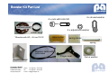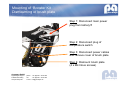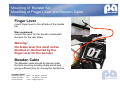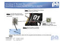
1
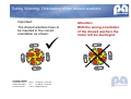
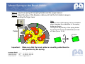
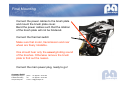
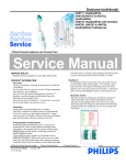
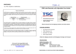
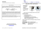
Booster Kit Installation Manual
For LEMCO® brushed DC motors
Issue date 22.02.2011
picoamps GmbH
Ingelsberger Weg 50
D-85604 Zorneding
www.picoamps.de
phone: +49 (0)8106 99 79 688
fax:
+49 (0)8106 99 79 689
e-mail: [email protected]
Booster Kit Part List
4 x nuts with bolts M4
4 x drused washer
stiffener plate*
4 x adjustment washer
rubber band*
*Obsolete with HD – Kit und TK1/2
cable holder
spring holder
spring
Bowden cable with
setscrews
Finger lever
angled bracket
picoamps GmbH
Ingelsberger Weg 50
D-85604 Zorneding
www.picoamps.de
phone: +49 (0)8106 99 79 688
fax:
+49 (0)8106 99 79 689
e-mail: [email protected]
frame washer
Booster: Restriction of Usage
Important Note: Only use with correct sense of rotation
The Booster Kit is designed for motors that spin clockwise
when looking onto the brush plate, and must only be used
with those. The instructions in this manual are therefore valid
for motors with clockwise rotation.
In principle, it is possible to also use it with motors that spin
counter-clockwise, which requires some modifications of the
Booster Kit.
Please contact picoamps in this case.
If the unmodified Booster Kit is used on motors with
wrong sense of rotation there is a risk that the motor will
be permanently damaged.
picoamps GmbH
Ingelsberger Weg 50
D-85604 Zorneding
www.picoamps.de
phone: +49 (0)8106 99 79 688
fax:
+49 (0)8106 99 79 689
e-mail: [email protected]
Mounting of Booster Kit
Dismounting of brush plate
Step 1: Disconnect main power
plug from battery!!!
Step 2: Disconnect plug of
temperature switch
Step 3: Disconnect power cables
and remove cover of brush plate
Step 4: Dismount brush plate
(4 x M4 Inbus screws)
picoamps GmbH
Ingelsberger Weg 50
D-85604 Zorneding
www.picoamps.de
phone: +49 (0)8106 99 79 688
fax:
+49 (0)8106 99 79 689
e-mail: [email protected]
Mounting of Booster Kit
Mounting of Finger Lever and Bowden Cable
Finger Lever
mount finger lever to the left side of the hanlde
bar.
We recommend:
monunt the lever for the booster underneath
the lever for the rear brake
Warning!
the brake lever the must not be
blocked or obstructed by the
finger lever for the booster
Bowden Cable
The Bowden cable should be placed under
the tank covering avoiding sharp bends and
giving sufficient play for moving the handle bar.
picoamps GmbH
Ingelsberger Weg 50
D-85604 Zorneding
www.picoamps.de
phone: +49 (0)8106 99 79 688
fax:
+49 (0)8106 99 79 689
e-mail: [email protected]
Mounting of Booster Kit
Mounting of angled bracket and frame washer
Step1: Dismount bearer from frame
remove screws on both ends
Step 2: On the left side place
angled bracket between bearer
and frame.
Step 3: On the right side
place frame washer
between bearer and frame.
Step 4: Mount bearer to frame
firmly tighten screws on both ends
Step 5: Place Bowden cable into the angled bracket between nut and setscrew.
picoamps GmbH
Ingelsberger Weg 50
D-85604 Zorneding
www.picoamps.de
phone: +49 (0)8106 99 79 688
fax:
+49 (0)8106 99 79 689
e-mail: [email protected]
Preparation of the brush plate Step 1
Note: the stiffener plate is already mounted on Heavy Duty Kit or Tuning Kit
Fit the delivered stiffener plate onto the tubes and shift tightly against the brush plate .
Note: One of the eight apertures in the stiffener plate is enlarged to provide space for the thermal switch.
Therefore the stiffener plate can only be mounted in one orientation. If the thermal switch is mounted in
the wrong position, this has to be corrected in step 2
Enlarged opening for thermal switch
picoamps GmbH
Ingelsberger Weg 50
D-85604 Zorneding
www.picoamps.de
phone: +49 (0)8106 99 79 688
fax:
+49 (0)8106 99 79 689
e-mail: [email protected]
Preparation of the brush plate Step 2
Note: the stiffener plate is already mounted on Heavy Duty Kit or Tuning Kit
On some brush plates the thermal switch is fixed to the
outer side of the adjacent brush tube so that the
stiffener plate will not fit.
In this case the thermal switch has to be carefully
removed using a thin blade.
The thermal switch has then to be fixed onto the inner
side of the correct brush tube as shown.
To fix the switch use a two component epoxy glue with
a temperature stability of at least 150°C
picoamps GmbH
Ingelsberger Weg 50
D-85604 Zorneding
www.picoamps.de
phone: +49 (0)8106 99 79 688
fax:
+49 (0)8106 99 79 689
e-mail: [email protected]
Preparation of the brush plate Step 3
Note: the stiffener plate is already mounted on Heavy Duty Kit or Tuning Kit
Place the delivered rubber ring directly behind the stiffener plate so that the stiffener plate
will not slip from the brush tubes.
picoamps GmbH
Ingelsberger Weg 50
D-85604 Zorneding
www.picoamps.de
phone: +49 (0)8106 99 79 688
fax:
+49 (0)8106 99 79 689
e-mail: [email protected]
Mounting of Spring and Cable Holder
The delivered spring and cable holder are mounted to the copper star on the side facing
toward the motor housing as shown below. Note that a cooling plate is placed between
spring holder and copper star.
Cable Holder
Copper Star
Spring Holder
(bent edge facing down)
picoamps GmbH
Ingelsberger Weg 50
D-85604 Zorneding
www.picoamps.de
phone: +49 (0)8106 99 79 688
fax:
+49 (0)8106 99 79 689
e-mail: [email protected]
Dispensing the glue to fix the brush plate mounting bolts
Clean and remove grease and oil from the four M4 mounting holes for the brush plate in the
motor housing before dispensing glue.
To fix the bolts use LOCTITE medium (or strong)
Dispense the glue into the M4 holes before mounting the bolts using a suitable tool (e.g. thin
stick).
There must be no glue on the motor housing
near the thread holes.
Motor Housing
picoamps GmbH
Ingelsberger Weg 50
D-85604 Zorneding
www.picoamps.de
phone: +49 (0)8106 99 79 688
fax:
+49 (0)8106 99 79 689
e-mail: [email protected]
Attention!
Remove excess glue on the housing
surface.
Otherwise the booster will not work.
Mounting of the brush plate mounting bolts
Step 1: Insert the bolts into the nuts and fix with medium force
(using a 2.5 mm hex wrench and a 4 mm socket wrench)
Step 2: Place the brush plate in the opening of the motor housing of the without inserting
cable and spring.
Step 3: on each bolt slide an adjustment washer and a drused washer and place the bolts
into the prepared M4 screw holes and tighten with medium force.
1.
3.
Wait for approximately 1 hour for the glue to harden.
Unscrew the nuts. When removing the nuts the bolts have to remain tightly in the housing.
If one of the bolts is loose the procedure has to be repeated.
Optionally use a stronger version of LOCTITE
picoamps GmbH
Ingelsberger Weg 50
D-85604 Zorneding
www.picoamps.de
phone: +49 (0)8106 99 79 688
fax:
+49 (0)8106 99 79 689
e-mail: [email protected]
Mounting Bowden cable on brush plate
Step 1: Dismount the brush plate again (the bolts have to stay in the motor housing)
Step 2: Before mounting the brush plate insert the cable into the cable holder.
24 sprocket pulley
Bowden
cable
Zug
30 sprocket pulley
Note:
Depending on the used belt pulley the
position of the motor in the frame is
different. Therefore the string holder
provides two different fitting holes to
fix the cable.
The rear position corresponds to the
24 sprocket pulley and the position
corresponds to the 30 sprocket pulley.
Step 3: Place the brush plate with mounted Bowden cable into the motor housing.
picoamps GmbH
Ingelsberger Weg 50
D-85604 Zorneding
www.picoamps.de
phone: +49 (0)8106 99 79 688
fax:
+49 (0)8106 99 79 689
e-mail: [email protected]
Mounting of the complete Brush Plate
Step1: Place one drused washer in each oval hole.
TAKE CARE OF THE CORRECT ORIENTATION (see also the following safety warning)
Step 2: Tighten the nuts with medium force.
Note:
The adjustment washers are not used for the final mounting of the brush plate. Mount the drused washers
only. Due to the removed adjustment washers the brush plate should have an axial play of 0.5 mm at all
four nuts when the nuts are
Important: Check that the brush plate does freely rotatate with low friction.
Dispense some grease on the drused washer to reduce the friction for the nut.
picoamps GmbH
Ingelsberger Weg 50
D-85604 Zorneding
www.picoamps.de
phone: +49 (0)8106 99 79 688
fax:
+49 (0)8106 99 79 689
e-mail: [email protected]
Safety Warning: Orientation of the drused washers
Important:
Attention:
The drused washers have to
be inserted in the correct
orientation as shown.
With the wrong orientation
of the drused washers the
motor will be destroyed.
picoamps GmbH
Ingelsberger Weg 50
D-85604 Zorneding
www.picoamps.de
phone: +49 (0)8106 99 79 688
fax:
+49 (0)8106 99 79 689
e-mail: [email protected]
Mount Spring to the Brush Holder
Step 1: Insert the spring at the spring holder and the angle bracket
Step 2: Adjust the play of the Bowden cable such that the full rotation range is
used by pulling the finger lever
Zug
Feder
Note:
The zero force of the spring can be increased
when changing the orientation of the spring
holder as shown.
Through the asymmetry of the spring holder
the spring will receive an additional pre-load
of 5 mm (or ca. 14 N)
5 mm
Important:
Make sure that the brush plate is smoothly pulled back to
zero position by the spring.
picoamps GmbH
Ingelsberger Weg 50
D-85604 Zorneding
www.picoamps.de
phone: +49 (0)8106 99 79 688
fax:
+49 (0)8106 99 79 689
e-mail: [email protected]
Final Mounting
Connect the power cables to the brush plate
and mount the brush plate cover.
Bend the power cables such that the rotation
of the brush plate will not be hindered.
Connect the thermal switch
Make sure that motor, transmission and rear
wheel are freely rotatable.
One should hear only the usual grinding sound
of the brushes. Otherwise remove the brush
plate to find out the reason.
Connect the main power plug, ready to go!
picoamps GmbH
Ingelsberger Weg 50
D-85604 Zorneding
www.picoamps.de
phone: +49 (0)8106 99 79 688
fax:
+49 (0)8106 99 79 689
e-mail: [email protected]