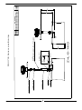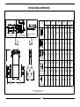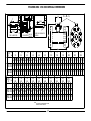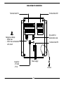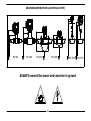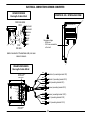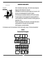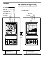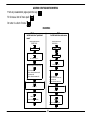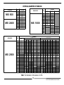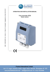
1
ML 200
Version 2.2X
The software version is visualised when
powering up the converter
ENGLISH
Emanml200-5.doc 16/11/00
1
C:\UFFICIO TECNICO\MANUALI\ML200\ML200 INGLESE\
-
INDEX
Introduction……………………………………………………………………………………………………………………………………………………………………………………….. pag. 4
Safety………………………………………………………………………………………………………………………………………………………………………………………………… pag. 5
GENERAL INFORMATION ON THE INSTALLATION
Flow direction…………………………………………………………………………………………………….………………………………………………………………….……………. pag. 6
MOUNTING RECOMMENDATION
Valid for: MS 500-1000-2400-2500……..……………………………………………………………………………………..……………………………………………………….… pag. 6-7
Valid for: MS 3700/3770……..…………………..………………………………………………………………………………………………………………………………………….. pag. 8
MS 3700/3770
MS 3700 sensor positioning…………………………………………………………….………………………………………….…………………………………….………………….
MS 3700 mounting instuctions…..………………………………………………………………………………………………….……………………………………………………...
MS 3770 sensor positioning ……………………………..…………………………………..……………………………………………………………………………………………..
MS 3770 mounting instuctions …………………………………..…………………………..………………….…………………………………………………………………………
pag.
pag.
pag.
pag.
9
10
11
12
OVERALL DIMENSIONS
MS 500, MS 1000, MS 2400, MS 2500 PN 10/64, MS 2500 ANSI 150-300……………………………………………………….......................……………………. pag. 13÷17
Converter.................................................................................................................................................................................................pag. 18
TECHNICAL CHARACTERISTICS:
Elettrical characteristics…………………………………………………………………………………………………………………………………………………………..…………… pag. 19
Environmental conditions of use…………………………………….……………………………………………..……………………………………………………………………... pag. 19
Operative temperature of the sensore…………………………………..………………………………….………………………….……………………………………….….…… pag. 20
ELECTRICAL CONNECTIONS
Rear view of converter………….………………………………………………………………………………………………………………………………………………..…………… pag. 21
-
Groundig instructions:
Metallic pipe…………………………….……………….…………………………………………………………………………..…………………………………………………………....pag. 22
Insulating pipe………………..……..……………………….…………………………………………………………………………………..…………………………….……….…….. pag. 23
Chatodic protection pipe…………………..………………………….……………………………………………………………………….……………………………….………...… pag. 23
-
Electrical connections sensor-converter……...………………….………………………………………………………….……………………………………………………….... pag. 24
Converter power supply………......................……………………………………………………………………………..…………………………………………………………... pag. 25
-
INPUT/OUTPUT
Terminal block M1 diagram………………………...…………………………………….………………………………………………………………………………………….………
Input operation stage….……………………………………..…………………………………………………………………………………………………………….……………….
On/Off output wiring (up to 1250 Hz) (low frequency)……………………………..………………………………………………………………………………………..….
- On/Off output wiring (up to 12500 Hz) (high frequency)….…………………………………..…………………………………………………………………………….……..
2
pag.
pag.
pag.
pag.
25
26
27
27
C:\UFFICIO TECNICO\MANUALI\ML200\ML200 INGLESE\
-
Wiring terminal M2 with module……………….………………………………………………………………………………………………………………………………………….…. pag. 28
MODALITY FOR TO ACCESS AT THE INSTRUMENT FUNCTIONS
Key board ML 200…….…………………………………………………………………………………………………………………….…………………………………….…………..… pag.
Visualization pages ML 200…………………………………………………………………………………………………………………………………………..……………………… pag.
Manufacturer pre-settings……………………….…………………………………………………………………………………………..………………………………………………. pag.
Access codes…………………………………………………………………………………………………….………………………………………………………..…………………..…. pag.
Block levels……………………………….…………………………………………………………………………………………………………………………………………………..…... pag.
Access configuration menu…………………………..…..…………………………………………………………………………………………………………………………………. pag.
29
30-31
32
33
34
35
PROGRAMMING FUNCTIONS
Function ML 200……………………….………………………………………………………………………………………………………………………………………………………... pag. 36-37
Function menu………………………………………………………………………………………………………………………………………………………………………..………….. pag. 38
-
-
Alarm messages, causes and action to be taken, anomalies codes……………………….………………………………………………………………….………………. pag. 61
Anomalies codes, intrpretation flags.......................................................................................................................................................... pag. 61
BATCH FUNCTIONS
Enable batch…..…………………………………………………………………………………………………………………………………………………………………………….……. pag. 62
Programming batch……………………………….………………………………………………………………………………………………………………………………………….... pag. 64
Important notes…………………………………………………………………………………………………………………………………………………………..……………………… pag. 65
START UP AND MAINTENANCE OF THE INSTRUMENTS
Recommendations..………..…………….………………………………………………………………………………………………….…………………………………………………. pag. 66
APPENDIX 1
Trasformations converter from compact version to separate version…..………………………………………………………………….………………………………... pag. 67
Trasformations converter from separate version to compact version ………………………………………………………………………………………….……………. pag. 68
APPENDIX 2
ND selection………………………………………………………………………………………………………………………………………………………………………..……………… pag. 69
Internal diameter of sensors……………………….………………………………………………………………………………………………………………………………………… pag. 70
APPENDIX 3
Error curve with converter ML 202….……………………………………………………………………………………………………….………………………………………….… pag. 71
Declaration of conformity…..…………………………..………………………………….…...………………………………..……………………………………….…………..……… pag. 72
3
C:\UFFICIO TECNICO\MANUALI\ML200\ML200 INGLESE\
INTRODUCTION
-
-
This manual is integral part of the product. Read carefully the instructions contained in it since it contains
important indications for the safety of use and of maintenance.
The technical information and the relative products of this manual could undergo modifications without
any previous notice.
The flow meter must be used for the use it has been built for. The improper use, possible tampering of
the instrument or parts of it and substitutions of any components not original, makes the warranty to
decay automatically.
The manufacturer is considered responsible only if the instrument in used in his original configuration.
It’s forbidden the reproduction of the present manual and of possible software supplied with the
instrument.
4
C:\UFFICIO TECNICO\MANUALI\ML200\ML200 INGLESE\
SAFETY
LEGEND
Dangerous voltage, terminals identified by this symbol are subject to variable voltages that
may exceed 60Vdc and cause electric shock: connecting terminal 12-13 pag. 21, 60Vdc max,
250 V max during coil’s magnetic field commutation phase.
Dangerous voltage, may cause severe electric shock
General warning
Precautions
- Before using the instrument, always make a sure connection to ground (see examples on pag.22-23)
- Verify that the mains voltage is the same written on the tag plate of the converter
- Pay attention not to connect the power supply to the outputs or the other terminals of M1/M2
- When the electric connections are completed, close carefully the instruments rear cover
- Avoid to open the instrument’s rear cover when the power is on.
- Avoid any attempt to repair the instrument. If the instrument is not functioning properly, please call
the nearest assistance service.
5
C:\UFFICIO TECNICO\MANUALI\ML200\ML200 INGLESE\
GENERAL INFORMATION ON THE INSTALLATION
Flow direction
ISOIL
Before install the sensor locate the direction of
the liquid in the piping
?
The sign of the flow rate is positive, when the flow direction
it’s (from – to +) as printed on the tag plate.
If after the installation, for plant request becomes
necessary reverse the sign of the flow, it's enough reverse
the sign of the coefficient KA
- FLOW DIRECTION +
ISOIL
RECOMMENDATION FOR MS 500-1000-2400-2500-3700-3770
//
//
ISOIL
Recommended lifting
Before tighten the nuts make sure that the
ending of the sensor are coaxial to those of the
pipe
The hooks are project exclusively
for the weight of the instrument
Centring cylinders
(before support the sensor,
making sure that the centring
cylinders be in the middle of
the sensor)
Method of upheaval recommended for all the
sensors equipped from eyebolt.
For sensor MS 1000 we recommend the use of
centring cylinders (available on request)
6
C:\UFFICIO TECNICO\MANUALI\ML200\ML200 INGLESE\
MS 500-1000-2400-2500
TO MAKE
TO AVOID
3 ND
Install the sensor away
from curves and hydraulic
accessories
ISOIL
Avoid the installation near
curves or hydraulic
accessories.
ISOIL
2 ND
During the functioning the
pipe must be completely
full of liquid, or completely
empty
ISOIL
For vertical installations
with descending flow
direction contact the
manufacturer
ISOIL
For vertical installations is
preferable an ascending
flow
ISOIL
Avoid the functioning with
the pipe partially empty.
ISOIL
ANTI VIBRATION JOINTS
For installations on long
pipe line, please use the
anti vibration joints
ISOIL
Avoid the installation of
the sensor in a long pipe
line, without any support
of the same.
ISOIL
LONG PIPES
LONG PIPE
ISOIL
Before tightening the nuts
approach as more possible
the flange of the piping to
the flange of the sensor
ISOIL
THICKNESS GASKET + 4mm
7
Avoid the approach of the
flange and counter flange
using the closing force of
the nuts.
C:\UFFICIO TECNICO\MANUALI\ML200\ML200 INGLESE\
MS 3700-3770
A
TO MAKE
20ND
10ND
TO AVOID
E
Install the sensor away
from curves and hydraulic
accessories
B
During the functioning the
pipe must be completely
full of liquid, or completely
empty
Avoid the installation near
curves or hydraulic
accessories.
F
Avoid the functioning with
the pipe partially empty.
For vertical installations
with descending flow
direction contact the
manufacturer
G
C
For vertical installations is
preferable an ascending
flow
H
D
The opening of the ball valve
before tighten the fixing nut
could cause the expulsion of
the sensor from the pipe line.
Before opening the ball
valve lock the centring
bush with the grain in
endowment
ATTENTION !!!
The indications of the figures A-B-C-E-F-G are valid also for the insertion sensor MS 3770.
8
C:\UFFICIO TECNICO\MANUALI\ML200\ML200 INGLESE\
9
Ø 1"
WELDED
PIPE Ø 1"
VALVE 1"
JACKET
Z=L-S-1/8D
MAX 140mm
O-RING SEAL
SENSOR
METER
(IT'S SCREW WHEN THE THE FIXING
NUT Ø 1" IS FIXED ON THE JACKET)
D
S
FIXING NUT Ø 1"
1/8D
BLOCK NUT Ø 16 MA
MS 3700 Sensor positioning
SIZE
ND RANGE
SIZE 1 from ND 80 up to ND 500
SIZE 2 from ND 80 up to ND 1000
SIZE 3 from ND 80 up to ND 2000
Z
L
C:\UFFICIO TECNICO\MANUALI\ML200\ML200 INGLESE\
L
480
621
880
3
2
1
Pic. 1
X
10
Pic. 2
Inferior estremity of
the jacket
(O-Ring seal)
- Screw the 1" jacket to the valve
ATTENTION: the O-Ring in the
jacket must be place underside
(near valve)
Pic. 3
Screw the valve Ø 1" to the welded pipe
Xmax=140mm
- Weld to the pipeline a pipe Ø 1".
ATTENTION: verify "X" dimension
(pic. 2).
Pipe line
Pipe Ø 1"
Pic. 9
Fixing
nut
5
4
Pic. 7
Pic. 5
- Open the valve
- Screw the sensor
up to "Z" dimension
- Verify the line up
(pic. 9)
- Tighten the block
nut manteining the
aligment
Pic. 8
- Insert the sensor at
close valve
- Tighten the fixing nut
with spanner (pic. 6)
Spanner 40mm
Pic. 6
N.B.: Le maniglie di inserimento
del sensore sono removibili
w
flo ction
dire
sensor
handles
Block
nut
Fixing nut
Pic. 4
MS 3700 Assemble Instructions
Z
C:\UFFICIO TECNICO\MANUALI\ML200\ML200 INGLESE\
JACKET Ø 1"
(WELDED)
GASKET
SENSOR
FIXING NUT Ø 1"
Seal side
1" gas
2,5
(Minimum
thickness)
Seal with fixed nut
2,0
D
3,0
L
Z
11
20,0
Z=L-S-1/8D-32
Minimum
height
Recommend dimensions of jacket
(in case the jacket it is not inclusive
in the supply)
SIZE
ND RANGE
SIZE 1 from ND 80 up to ND 500
SIZE 2 from ND 80 up to ND 1000
SIZE 3 from ND 80 up to ND 2000
1/8D
MS 3770 Sensor positioning
L
C:\UFFICIO TECNICO\MANUALI\ML200\ML200 INGLESE\
L
176
244
462
12
C:\UFFICIO TECNICO\MANUALI\ML200\ML200 INGLESE\
Z
weld the jacket to
the pipe line
Pipe line
Jacket Ø 1"
Pic. 2
ATTENTIONE: in relation to the Ø of
the pipeline consider the
necessary over-metal for
welding
z
Pic. 6
Pic. 4
Pipe line
Jacket Ø 1"
Gasket
Sensor
Pic. 3
- Tighten the nut with
spanner (pic. 5)
maintaining the alignment.
The fixing of nut must
assure the seal of the
inside gasket
- Line up longitudinally
the connector box with
pipe line axle (pic.6).
Flow direction
Spanner 40mm
Pic. 5
- Introduce the sensor in the
Jacket Ø 1"
- Introduce in the sensor the
gasket
MS 3770 Assemble Instructions
Cut the jacket Ø 1" like in picture 1
Pic. 1
Over-metal
MS 500 OVERALL DIMENSIONS
112,0
DN
100,0
3
L
8,0
133,0
,0
93
6
FITTINGS
L
10
FITTINGS
L
FITTINGS
15
L
20
FITTINGS
L
FITTINGS
126,0
54,0
ISOIL
,0
30
106,0
,0
146
ML 190
CONVERTER ML 200
PRE - AMPLIFIER
COVER FOR SEPARATE
VERSION
128 DN 25 128 DN 25 128 DN 25
SMS
128 DN 10 128 DN 10 128 DN 10 128 DN 15 128 DN 20
DN
34,0
I
DIN 11851
170,0
TRICLAMP
ISO 2852
Flanges
ANSI 150
FITTINGS
FITTINGS
80,0
L
Flanges UNI
2278 PN 16
76,0
128 I=12,7 128 I=12,7 128 I=12,7 128 I=17,2 128 I=21,3
200
1/2"
200
1/2"
200
1/2"
200
1/2"
200
3/4"
200 DN 10 200 DN 10 200 DN 10 200 DN 15 200 DN 20
128
1\4"
128
3\8"
128
1\2"
128
3\4"
128
1"
Gas - NPT
stainless steel and P.P.
N.B.: THE OVERALL DIMENSIONS CAN BE
CHANGE WITHOUT NOTICE
13
C:\UFFICIO TECNICO\MANUALI\ML200\ML200 INGLESE\
MS 1000 OVERALL DIMENSIONS
112,0
8,0
133,0
,0
93
100,0
ISOIL
0
30,
54,0
126,0
106,0
PRE - AMPLIFIER
6,0
14 ML 190
CONVERTER ML 200
COVER FOR SEPARATE
VERSION
G
DN 25 32
24,0
D
H
100
+0
-3
+0
-3
40 50 65
80 100 125 150 200 250 300 350 400
+0
-3
+0
-3
+0
-3
+0
-3
+0
-3
+0
-3
+0
-3
+0
-3
+0
-5
+0
-5
+0
-5
100 100 100 100 150 150 150 180 180 200 250 300 350 400
H
147 153 161 177 199 209 235 263 291 362 417 467 527 579
D
56
62
70
86
G
_
_
_
_
108 118 144 172 200 271 326 376 436 488
_
_
_
3,6
3,8
5,0
_
_
Weight
(Kg)
1,2 1,6
Usable
flanges
PTFE - EBONITE: PN10 PN16 PN25 PN40 ANSI150 ANSI300
P.P.: PN10 PN16 ANSI150
1,8 2,0
144 194 244 294 344
7,8 8,2 18,2 24,0 27,0 32,0 39,0
PN10 PN16 ANSI150
(PTFE - EBONITE)
DN
L
N.B.: THE OVERALL DIMENSIONS CAN BE
CHANGE WITHOUT NOTICE
14
+0
-5
L
C:\UFFICIO TECNICO\MANUALI\ML200\ML200 INGLESE\
MS 2400 OVERALL DIMENSIONS
112,0
32
40
50
65
80
100
170
170
170
180
180
180
76
DN 25
76
DN 25
8,0
100,0
ISOIL
126,0
76
,0
30
106,0
190
CONVERTER ML
ML 200
PRE - AMPLIFIER
DN 25
6,0
14
COVER FOR SEPARATE
VERSION
170
180
76
DN 32
170
170
170
180
180
180
76
76
76
DN 38
DN 40
DN 38
208
208
208
180
180
180
114
114
DN 51
208
180
114
DN 63,5
DN 50
234
200
140
DN 65
114
H
25
H
L
D
F
H
L
D
F
H
L
D
F
H
L
D
F
H
L
D
F
H
L
D
F
H
L
D
F
SMS
54,0
TRICLAMP
ISO 2852 DIN 11851
DN
133,0
,0
93
DN 51
208
180
FITTINGS (F)
FITTINGS (F)
114
DN 63
234
234
234
200
200
200
140
140
140
DN 76,1
DN 80
DN 76
262
262
262
200
200
200
168
168
168
100
D
L
N.B.: THE OVERALL DIMENSIONS CAN BE
CHANGE WITHOUT NOTICE
DN 101,6 DN 100 DN 104
15
C:\UFFICIO TECNICO\MANUALI\ML200\ML200 INGLESE\
MS 2500 PN10/64 OVERALL DIMENSIONS
B
133,0
C
8,0
A
,0
93
112,0
100
A-B-C
100,0
PRE - AMPLIFIER
,0
30
106,0
,0
146 ML 190
CONVERTER ML 200
D
126,0
H
54,0
ISOIL
COVER FOR SEPARATE
VERSION
L
DN
25
32
40
50
65
80
100
125
150
200
250
L H D L H D L H D L H D L H D L H D L H D L H D L H D L H D L H D
350 399 340 450 454 395
PN 10
200 248 185 200 263 200 250 283 220 250 313 250 300 344 285
350 399 340 450 460 405
PN 16 200 185 115 200 203 140 200 213 150 200 228 165
350 415 360 450 475 425
PN 25
200 248 185 200 263 200 250 294 235 250 325 270 300 355 300
350 425 375 450 493 450
PN 40
PN 64 200 198 140 200 209 155 200 220 170 200 233 180 200 257 205 200 267 215 250 297 250 250 330 295 300 377 345 350 435 415 450 491 470
DN
PN 10
PN 16
PN 25
PN 40
PN 64
300
350
400
450
500
600
700
800
900
1000 1200
L H D L H D L H D L H D L H D L H D L H D L H D L H D L H D L H D
500 504 445 550 564 505 600 620 565 600 670 615 600 725 670 600 830 780 700 945 895 800 1058 1015 900 1158 1115 1000 1269 1230 1200 1490 1455
500 515 460 550 575 520 600 630 580 600 690 640 600 758 715 600 879 840 700 949 910 800 1060 1025 900 1160 1125 1000 1284 1255 1200 1506 1485
500 535 485 550 598 555 600 659 620 600 709 670 600 769 730 600 880 845 700 989 960 800 1106 1085 900 1206 1185 1000 1329 1320 1200 1539 1530
500 558 515 550 619 580 600 695 660 600 720 685 600 784 755 600 911 890 700 1016 995 800 1149 1140 900 1259 1250 1000 1369 1360 1200 1579 1575
500 545 530 550 603 600 600 670 670
N.B.: THE OVERALL DIMENSION CAN BE
CHANGE WITHOUT NOTICE
16
C:\UFFICIO TECNICO\MANUALI\ML200\ML200 INGLESE\
MS 2500 ANSI 150-300 OVERALL DIMENSIONS
A
B
112,0
C
8,0
133,0
,0
93
100
A-B-C
100,0
ISOIL
6,0
14
COVER FOR SEPARATE
VERSION
ML 190
CONVERTER ML 200
PRE - AMPLIFIER
D
106,0
H
,0
30
54,0
126,0
L
DN
INCH
mm
1"
25
1" 1/4
32
1" 1/2
40
2"
50
2" 1/2
65
3"
80
4"
100
5"
125
6"
150
8"
200
10"
250
12"
300
L H D L H D L H D L H D L H D L H D L H D L H D L H D L H D L H D L H D
ANSI 150
ANSI 300
DN
INCH
mm
200 181 108 200 192 118 200 207 127 200 222 152 200 245 178 200 259 191 250 288 229 250 315 254 300 341 279 350 401 343 450 461 406 500 527 483
200 190 124 200 199 133 200 221 156 200 228 165 200 251 191 200 268 210 250 300 254 250 328 279 300 360 318 350 420 381 450 480 445 500 546 521
14"
350
16"
400
18"
450
20"
500
24"
600
26"
650
30"
750
34"
850
36"
900
42"
1000
L H D L H D L H D L H D L H D L H D L H D L H D L H D L H D
ANSI 150
ANSI 300
550 582 533 600 639 597 600 688 635 600 751 699 600 866 813 650 921 870 750 1032 984 850 1149 1111 900 1206 1168 1000 1381 1346
550 607 584 600 664 648 600 726 711 600 770 775 600 916 914 650 1002 972 750 1121 1092 850 1230 1207 900 1292 1270 1000 1467 1448
N.B.: THE OVERALL DIMENSIONS CAN BE
CHANGE WITHOUT NOTICE
17
C:\UFFICIO TECNICO\MANUALI\ML200\ML200 INGLESE\
CONVERTER: OVERALL DIMENSIONS
112
112
150
200
133
133
108
108
150
108
108
25
Compact
version
converter
Separate
version
converter
112
120
133
108
150
108
84
Panel version
Converter
18
C:\UFFICIO TECNICO\MANUALI\ML200\ML200 INGLESE\
TECHNICAL CHARACTERISTICS
ELECTRIC CHARACTERISTICS
Classification of the instrument: class I, IP 67, category of installation II
Power supply Power supply
versions
voltage
HV
90÷265 Vac
LV
18÷45 Vac/dc
LLV
10÷35 Vdc
Power supply
frequency
44÷66 Hz
0-44÷66 Hz
Pmax
20W/25VA
20W/25VA
20 W
current
max
0,25 A
1,6 A
1,5 A
Input/output isolation:
- Input/output are insulated up to 500V
- The output 4÷20 mA and the output 24 Vdc are electrically connected
ENVIRONMENTAL CONDITIONS OF USE
-
The instrument can be installed inside or outside of buildings, but avoid direct sunlight exposition
Altitude: from –200 a 6000 m (from -656 to 19685 feet)
Temperature range: (see appendix 2)
Humidity range: 0÷100% (IP 67)
Line voltage range: (see table on technical characteristics)
19
C:\UFFICIO TECNICO\MANUALI\ML200\ML200 INGLESE\
OPERATING TEMPERATURE OF THE SENSOR
SENSOR WITH EBONITE LINING
Liquid temp.
Min.
Max
°C °F °C
°F
0
32 80 176
SENSOR WITH PP LINING
Amb. Temp.
Min.
Max
°C °F
°C
°F
-5
23
60
140
Liquid temp.
Min.
Max
°C °F °C
°F
0
32 60 140
Amb. Temp.
Min.
Max
°C
°F
°C
°F
0
32
60 140
SENSOR WHITH PTFE LINING
Liquid temp.
Min.
Max
°C
°F
°C
°F
-20
-4
150
302
Amb. Temp.
Min.
Max
°C
°F
°C
°F
-10
14
60 140
OPERATING TEMPERATURE OF THE CONVERTER
CONVERTER ML 200
Amb. Temp.
Min.
Max
°C
°F
°C
°F
-20*
-4*
60 140
* For discontinuous use, is necessary the installation of a heating resistance
20
C:\UFFICIO TECNICO\MANUALI\ML200\ML200 INGLESE\
REAR VIEW OF CONVERTER
Terminal block M1
Terminal block M2
1 2 3 4 5 6 7 8 9 10
11 12 13 14 15 16 17 18 19 20
21 22 23 24 25 26
27 28 29 30 31 32
Dip switch for
Dangerous voltage:
- 60Vdc max
- 250 V max commutation
coil's circuit
Socket for
- MT 200
- IF 02
enable block level
Terminal block M3
Power supply
to cover
21
C:\UFFICIO TECNICO\MANUALI\ML200\ML200 INGLESE\
GROUNDING INSTRUCTION (with METALLIC PIPE)
ISOIL
ISOIL
ISOIL
ISOIL
MS 500
MS 2400
MS 1000
MS 2500
MS 3700
MS 3770
ALWAYS connect the sensor and converter to ground
22
C:\UFFICIO TECNICO\MANUALI\ML200\ML200 INGLESE\
For the sensors MS 500-1000-2500, in the cases listed below, see the following instruction:
INSULATING GASKET
ISOIL
If the sensor has to be mounted on a pipe made of
an insulating material, then for grounding purposes of
the liquid there are two possibility:
Install two metallic ring (available on request)
between the sensor flanges and the counter flanges of
the pipe line; or:
Use a sensor with the additional grounding electrode.
METALLIC RING
INSULATING GASKET
ISOIL
INSULATING BUSH
METALLIC RING
If the sensor must be install in the piping with a
chatode protection, some precautions should be
taken:
1) Grounding metallic rings should be provided to
ground the liquid
2) the sensor should be insulated from the piping,
using gasket between the rings and the sensor
and insulating bushes for the tightening tie
rods.
The flanges pipe should be connected one to
the other (by-passing the sensor) with a
copper plait 6 mm2 section.
23
C:\UFFICIO TECNICO\MANUALI\ML200\ML200 INGLESE\
ELECTRICAL CONNECTIONS SENSOR-CONVERTER
SEPARATE VERSION
Max length of cable: 20 mt
CONVERTER ML 200 – INTERNAL REAR VIEW-
Electrodes cable
C013
1
Electrode 1
C012
Coil cable
2
Electrode 2
3
4
11
12
Common
Shield
Shield
Coil 1
13
Coil 2
Terminal block M1
1 2 3 4 5 6 7 8 9 10
11 12 13 14 15 16 17 18 19 20
Dangerous voltage:
- 60Vdc max
- 250 V max commutation
coil's circuit
Sudden movements of the electrodes cable, can cause
noises on measure
PRE-AMPLIFER VERSION
Max length of cable: 500 mt
Green (electrode 1)
Black (electrode 2)
White/black (common)
Red (coil 1)
Black (coil 2)
White
Black
Orange
Red
Blu
1 2 3 4 5 6 78 910
From pin 6 to pin 10:
cable connected
to the converter
From pin 1 to pin 5:
cable connected
to the sensor
Green
1
Black
2
Electrode 2 (connecting terminal 2 M1)
Shield
4
Shield (connecting terminal 4 M1)
3
Common (connecting terminal 3 M1)
White
Black
Cable C014
Electrode 1 (connecting terminal 1 M1)
Shield
11
Common (connecting terminal 11 M1)
Red
12
Coil 1 (connecting terminal 12 M1)
Black
13
Coil 2 (connecting terminal 13 M1)
24
C:\UFFICIO TECNICO\MANUALI\ML200\ML200 INGLESE\
CONVERTER POWER SUPPLY
REAR CONVERTER
before connecting the power supply, verify that the mains voltage falls
between the limits indicated on the tag plate
- ATTENTION: the converters on dc power supply line (LLV version: 10-35
Vdc) they not protected against the inversions of polarity.
- For the wiring use only approved conductors, with fire-proof properties.
L
N
(-) (+)
- The power supply line must be equipped with a external protection for
Cover
current overload (fuse or automatic line breaker with limiting capacity not
Power supply
greater than 10 A).
- Provide in the proximity of the instrument a circuit breaker that must be
easily accessible from the operator and clearly identified.
- from the operator, and clearly identified.
For information concern the characteristics of meter’s power supply, see pag. 19 “technical characteristics”
Terminal M3
-
IN/OUT
Terminal block M1 diagram
E1
ELECTRODES
E2
C
SC
INPUT
+
-
RS485
B
A
4-20mA
+
-
1 2 3 4 5 6 7 8 9 10
11 12 13 14 15 16 17 18 19 20
SC
B1
COILS
B2
SC
+
24V
CE
E
OUT1
25
C
E
OUT2
24V
C:\UFFICIO TECNICO\MANUALI\ML200\ML200 INGLESE\
26
C:\UFFICIO TECNICO\MANUALI\ML200\ML200 INGLESE\
0-1,5 V
0-1,5 V
0-1,5 V
0-1,5 V
0-1,5 V
T
T
10 Hz
20 Hz
50 Hz
80 Hz
150 Hz
Speed rate
Tmin
220 ms
110 ms
45 ms
30 ms
15 ms
START BATCH
SCALE 1
SCALE 2
3-40 V
0-1,5 V
TOTSLISER ACTIVE
20
6
5
15
N.B.:with Tmin<T<1sec. = start/stop batch
with T >1 sec.=zero resetting batch In course
ATTENTION: the time T must be
? to Tmin
Tmin = 100ms
Start/stop batch from remote
input
(if actine function: 37)
“Appendix 1”
Range change from remote input
(if active function: 36)
Totaliser lock from remote input
(if active function: 34)
Totaliser reset from remote input
(if active functions: 30,31,32,33)
withTmin<T<1sec. = auto-calibration
with T > 1 sec. = Autozero
(if active functions: 35 and batch OFF)
STOP BATCH
T
RESET
N.B.:
LOCK TOTALISERS
Tmin = 100ms
3-40 V
3-40 V
3-40 V
T
Tmin = 100ms
3-40 V
LOCK
0
10 K
+24
WIRING INPUT
internal power supply
Auto-calibration from remote input
TERMINAL 6 (-)
AUTO-CALIBRATION ON
AUTO-CALIBRATION OFF
3-40 V
TERMINAL 5 (+)
3/40 Vdc (ON)
0/1,5 Vdc (OFF)
10 K
INPUT WIRING
external power supply
INPUT OPERATION STAGE
On/off outputs wiring(Up to 1250 HZ) (low frequency):
OUT 1/OUT 2 standard
OUT 3/OUT 4 with modules (page 24)
-
On/off outputs wiring(Up to 1250 HZ)
Terminal 16
(Out1)
18
(Out2)
-
43 V
-
Terminal 17
(Out1)
19
(Out2)
-
Opto-insulated output with floating collector and emitter terminals
freely connectable
Maximum switching voltage: 40 Vdc
Maximum switching current: 100mA
Maximum saturation voltage between collector and emitter @100mA:
1,2V
Maximum switching frequency (load on the collector or emitter,
RL=470? , VOUT=24Vdc): 1250Hz
Maximum revers current bearable on the input during and accidental
polarity reversion (VEC): 100mA
Insulation from other secondary circuits: 500 Vdc
On/off output wiring (Up to 12500 HZ) (high frequency): only with ME 201 module
-
On/off output wiring (Up to 12500 HZ)
+
Terminal 30
-
43 V
Terminal 29
-
27
Opto-insualted output with floating collector and emitter terminals
freely connectable. In order to get the maximum performances it is
necessary to connect the emitter to the common terminal of the
outputs (0V), while the load has to be on the collector. This output is
internally connected to the power supply source 24 Vdc available on
the terminal block.
Maximum switdhing voltage: 40Vdc
Maximum switdhing current: 100mA
Maximum saturation voltage between collector and emitter @ 100mA,
load on the collector and internal power supply: 0,3V
Maximum saturation voltage between collector and emitter @ 100mA,
load on the emitter and internal power supply: 3V
Maximum switching frequency, load on the collector and internal
power supply: (RL=470? , VOUT=24Vdc): 12500Hz
Maximum switching frequency, load on the emitter or external power
supply: (RL=470? , VOUT=24Vdc): 2500Hz
Insulation from the other secondary circuits (except 24V and 4…20mA
outputs): 500 Vdc
C:\UFFICIO TECNICO\MANUALI\ML200\ML200 INGLESE\
WIRING TERMINAL M2 WITH MODULE:
ME200: 2 programmable on/off outputs
ME201: 1 programmable on/off output + 1 high frequency output
ME202: 1 0/4…20mA output + 2 programmable on/off output
ME203: 1 RS232 port + 2 programmable on/off outputs
ME204: 1 RS232 port + 2 programmable on/off outputs + 1 0/4…20mA outpu
ME220: see the manual
OUT 3
RS232
E C CTS RD TD SG
ME207: 2 relay outputs with 1 NO contact + 1 NC contact each,
2A 250Vac, 60W/125Va
OUT 3
NO NC C
21 22 23 24 25 26
OUT4
NO NC C
21 22 23 24 25 26
27 28 29 30 31 32
- + E C
4..20mA OUT 4
ME205: 2 relay outputs with 1 NO contact + 1 NC contact each,
2A 60Vac, 60W/125Va
27 28 29 30 31 32
SC
SC
LEGEND:
LEGEND:
SC: Cable shield, electrically connected to ground and to the casing
CTS: Input terminal of the signal “CLEAR TO SEND” of the RS232 port
RD: Input terminal of the signal “RECEIVE DATA” RS232 port
TD: Output terminal of the signal “TRASMIT DATA” of the RS 232 port
SG: Terminal “SIGNAL GROUND” common to all signals of the RS232 port
C: Terminal conncted with the MANIFOLD of the transistor of the on/off
output
SC: Cable shield, electrically connected to ground
and to the casing
C: relay - common
NC: Normaly closed contact
NO: Normaly open contact
* The module name is visualized at the start of converter.
28
C:\UFFICIO TECNICO\MANUALI\ML200\ML200 INGLESE\
ACCESS TO THE INSTRUMENT
KEY BOARD
The ML 200 programming keyboard is made up by three keys:
SHORT PRESSING (< 1 SECOND):
It increases the numeric figure or the parameter selected by the cursor
It goes to the previous subject on the menu
batch start/stop (when enabled)
LONG PRESSING (> 1 SECOND):
It decreases the numeric figure or the parameter selected by the cursor
It goes to the next subject on the menu
SHORT PRESSING (< 1 SECOND):
It moves the cursor rightward on the input field
It goes to the following subject of the menu
It change the display of the process data
LONG PRESSING (> 1 SECOND):
It moves the cursor leftward on the input field
It goes to the previous subject on the menu
SHORT PRESSING (< 1 SECOND):
It enter /leaves the selected function
It enables the main menu for the intrument configuration
It cancels the selected function under progress
LONG PRESSING (> 1 SECOND):
It leaves the current menu
It enables the totalizer reset request (when enabled)
It confirms the selected function
29
C:\UFFICIO TECNICO\MANUALI\ML200\ML200 INGLESE\
flow rate value
% full scale
date time or allarm
revers totalizer
VISUALIZATION
ATTENTION: The direct exposure of the converter to the solar rays, could
damage the liquid crystals display
Flow rate value and graphic visualization
Alarm on signal
(meaning of flags page 61)
direct totalizer
Sampling rate
tasca trasparente per inserimento logo
Scale (1 = low)
(2 = high)
push
tasca trasparente per inserimento logo
Visualization page “A”
Visualization page “B”
30
C:\UFFICIO TECNICO\MANUALI\ML200\ML200 INGLESE\
PAGE ML 200
N.B. Contrast set (see page 57 pos. 51)
flow rate value
scale in use
% full scale (bar grph)
unit of measure
Time scale (see pos. 17)
Active scale
flow direction
tasca trasparente per inserimento logo
% full scale
push
tasca trasparente per inserimento logo
Visualization page “C”
Visualization page “D”
31
C:\UFFICIO TECNICO\MANUALI\ML200\ML200 INGLESE\
MANUFACTURER PRE-SETTINGS
The converter is programmed and delivered according to the following STANDARD configuration:
??
??
??
Dip switch: ON (Switch positioned close to the lock symbol)
Security level: 3 (page 59 pos. 60)
Access code L” = 11111 (page 59 pos. 59)
With such a pre-setting, when powered on, the instrument will show one of the 4 visualisation pages (pict. A-B-C-D on pages 3031). By pressing the button
you can get to the “Quick start menu”:
the visualisation page shown aside may
contain different parameters
from those shown on your instrument,
depending on the pre-setting
required by the customer
The “Quick start menu” may be set without entering any access code (see example 1 on page 35).
To enter the Main Menu, position the cursor on the word “Main menu” and press the button
; then enter the level 2 access
code L” = 11111 and press the key
.
All the functions of the converter are now available, apart those reserved to the service (access code of higher level).
Dip switch
REAR CONVERTER
Power supply
32
Cover
C:\UFFICIO TECNICO\MANUALI\ML200\ML200 INGLESE\
ACCESS CODES
The information of this manual are related to all the functions available with L2 security level.
All the functions available through access codes of higher level are protected and reserved to the service.
Access code description: L2 (menu “11 Internal Data, page 59 pos. 59)
A) with code L2 = 11111 (with this code only) you access the “Quick start menu”, and you can follow the programming
procedure as described on page 28
B)
with code L2 = 22222 (with this code only) you disable the request of code L2 and you can proceed with the programming
without entering any access code (up to L2 security level)
NOTE: the availability of the functions is related to the selected block (see page 34)
C)
* with L2 customised (freely chosen by the user) you can proceed programming all the functions up to L2 security level,
entering its code whenever you enter the Main menu
*ATTENTION: take note very carefully of the customised code you have chosen, since there is no way for the user to retrieve it is
forgotten
33
C:\UFFICIO TECNICO\MANUALI\ML200\ML200 INGLESE\
BLOCK LEVELS
If for several reasons you need to change the level of block of the instrument, follow the steps:
?? Set the dip switch on OFF position (opposite side than the lock symbol, see pict. On page 32)
?? Access the Main Menu (see page 32)
?? Press several times the key
, till you don’t reach the menu “11: Internal data” and then press
?? Press the key
and
to enter the function “Block level”
?? Choose the desired level of block by pressing the key
and confirm the choice by pressing the key
To enable the level of block you selected place back the DIP switch to the original ON position marked with a lock symbol
(see pict. On page 32)
The available levels of block are the following:
Level 0:
it completely disables the access to the functions. You can perform the following functions through the keyboard:
?? Changing the display mode
?? Dosing Start/stop (when such a function is enabled)
?? Data printing (when such a function is enabled)
Level 1:
it enables the access to the following functions:
?? Totalisers re-setting
?? Dosing functions modifications
Level 2:
it enables the access to the following functions:
?? Quick start menu (see code level 2 = 11111)
?? Scale (full enabling)
?? Display (partial enabling)
?? Diagnostics (partial enabling)
Livello 3:
it enables the access to all the functions of level 2
When the Dip-switches are on OFF position, all the functions are enabled.
The functions requiring an access code higher than L2 are reserved to the service.
34
C:\UFFICIO TECNICO\MANUALI\ML200\ML200 INGLESE\
ACCESS CONFIGURATION MENU
From any visualizzation pages push this key:
For choose a item of menu push:
Per enter in a item of menu:
EXAMPLES
EX. 1
EX. 2
Set full scale from main menu
Set full scale from “quick start
menu”
FROM VISUALIZATION
PAGES PUSH:
FROM VISUALIZATION
PAGES PUSH:
FS1
KEYCODE:
00000
choose the volume unit with the key:
FS1
dm³, dal, hl, m³, ml....
choose the volume unit with the key:
dm³, dal, hl, m³, ml....
choose the type of unit with the key:
choose the type of unit with the key:
metric volume units
British or American volume units
metric mass units
British or American mass units
metric volume units
British or American volume units
metric mass units
British or American mass units
choose the time unit of measure with the key:
s, m, h, d,
choose the time unit of measure with the key:
s, m, h, d,
Set the numeric value with the key:
Set the numeric value with the key:
Use the key:
Use the key:
for move in the numeric side
for move in the numeric side
35
C:\UFFICIO TECNICO\MANUALI\ML200\ML200 INGLESE\
N° MENU
DESCRIPTION
1.SENSOR
1
FUNCTION
ND
2
SET ND
2.SCALES
8
FS1
KA
3
SET KA
9
FS1
10
FULL SCALE 1 VALUE SET FULL SCALE 2 VALUE SET
CABLE LEN.
SET CABLE LENGTH
IMP1
11
PULSE VALUE SET FOR CHANNEL 1
IMP2
PULSE VALUE SET FOR CHANNEL 2
VOLUME UNIT
VOLUME UNIT
MISURE UNIT
MISURE UNIT
TYPE OF UNIT
TYPE OF UNIT
TYPE OF UNIT
TIME UNIT OF MEASURE
TIME UNIT OF MEASURE
NUMERIC VALUE
NUMERIC VALUE
NUMERIC VALUE
NUMERIC VALUE
T. CONST
TIME CONTANT SET
5.INPUTS
4
TYPE OF UNIT
3.MEASURE 17
4.ALARMS
KL
SET KL
24
MAX THR
18
SKIP THR
19
ACCELERATION THRESHOLD SET
25
26
MIN THR
MAXIMUM FLOW RATE VALUE ALARM SET
MINIMUM FLOW RATE VALUE ALARM SET
30
31
T+ RESET
ENABLE RESE OF TOTAL DIRECT FLOW TOTALIS.
P+ RESET
PEAK THR
20
CUT-OFF
ANOMAL SIGNAL PICK CUT OFF THRESHOLD SET LOW FLOW ZERO THRESHOLD SET
HYST
27
HYSTERESIS THRESHOLD
32
T- RESET
E.P. THR
EMPTY PIPE DETECTION THRESHOLD SET
33
P- RESET
ENABLE RESE OF PARTIAL DIRECT FLOW TOTALIS. ENABLE RESE OF TOTAL REVERSE FLOW TOTALIS. ENABLE RESE OF PARTIAL REVERSE FLOW TOTALIS.
FUNCTION ACTIVE WITH INPUT IN VOLTAGE
6.OUTPUTS
38
OUT.1
39
OUT.2
40
OUT.3
41 OUT.4 (FRQ. MAX 12.5KHz) (OPT.)
SEE THE TAB REFER TO THE FUNCTIONS FOR OUTPUTS : MENU 6 "OUTPUT"
7. COMUNICATION
44
ADDRESS
45
NETWORK ADDRESS SET
8. DISPLAY
48
TOT DECIMALS
SPEED 1
46
SPEED RS485 OUTPUT
49
LANGUAGE
50
N° DECIMALI TOTALIZZATORI E=ENGL. I=ITAL. F=FRENCH S=SPAGN.
9.DATA LOGGER 52
ACQUISITION
AUTOMATIC DATA LOGGIN ENABLE
10.DIAGNOSI 57
SELFTEST
METER AUTOTEST FUNCTION
11.INTERNAL DATA
59
L2 KEYCODE
LIVELL 2 ACCESS CODE ENTER
53
INTERV. (h)
47
DISP. FR.
51
DD/MM/YY 00:00
DATE AND TIME SET
PRINT (OPT.)
ENABLE PRINT FUNCTION (ONLY WITH ME 203-204)
REFRESH DISPLAY SET
54
INTERVAL FOR DATA LOGGING FUNCTION
58
SPEED 2
VELOC. RS232 OUTPUT
CONTRAST
CONTRAST SET
55
DISPLAY DATA
DISPLAING DATA STORED
SIMULATION
FLOW RATE SIMULATION ENABLE
60
LOCK LEVEL
61 LOAD FACT. PRES.
LOCK LEVEL SET
FACTORY VALUE RECALL
36
62 LOAD USER PRES.
USER VALUE RECALL
C:\UFFICIO TECNICO\MANUALI\ML200\ML200 INGLESE\
ML 200
5
E.P. DETECT
ON/OFF
KEYCODE LEVEL
6
AUTOZERO CAL.
7
E.P. CALIBR.
START AUTOZERO CALIBRATION
START EMPTY PIPE CALIBRATION
13
14
ENABLE/DISABLE EMPTY PIPE TEST
12
TPUL1
DURATION OF THE PULSE CHANNEL 1
21
AUTOCAL.
TPUL2
FRQ1
15
FRQ2
DURATION OF THE PULSE CHANNEL 2 FULL SCALE FREQUENCY SET CHAN. 1 FULL SCALE FREQUENCY SET CHAN. 2
ACTIVE IF CHANNEL 2 IS ON PULSE
ACTIVE IF CHANNEL 1 IS ON FREQUENCY
22
23
ATORANGE
ACTIVE IF CHANNEL 2 IS ON FREQUENCY
16
SW
SPECIFIC GRAVITY SET
ACTIVE IF MASS UNIT HAS BEEN SELECTED
E. SAVING
ENAB./DISAB THE AUTOCALIB FUNCTION ENAB./DISAB. THE AUTOMATIC CHANGE OF SCALE AUTAMATIC ENERGY SAVING FUNCTION ENABLE
28
mA VAL.FAULT
29
Hz VAL.FAULT
4/20 mA CURRENT ALARM SET FREQUENCY OUTPUT ALARM SET
ONLY IF CHANNEL 1 OR 2 IN FREQUENCY MODE
34
COUNT LOCK
LOCK TOTALISER
35
CALIBRATION
AUTOZERO CALIBR. EXTERNAL COMMAND ENAB.
36
RANGE CHANGE
RANGE CHANGE EXTERNAL COMMAND ENAB.
37
BATCH
BATCH START/STOP EXTERNAL COMMAND ENABLE
FUNCTION ACTIVE WITH INPUT IN VOLTAGE
42
OUT.mA1
CHOOSE CURRENT VALUE OUTPU 1
43
OUT.mA2 (OPT.)
CHOOSE CURRENT VALUE OUTPU 2
START/END RANGE (0/4-20/22 mA) AND FIELD (+,-,±,-0+)
The opportune selection of the channel 1 and 2,
allows to be on the 2 output on/off 2 separate
signals of volume and/or frequency
56
CLEAR DATA
LOGGED DATA CANCEL FUNCTION
63
Some of the functions above suitable are visualised
on the display only with the qualification of other
functions or with the insertion of additional modules
(sees details in the following chapters)
SAVE USER PRES.
USER VALUE SAVE
37
C:\UFFICIO TECNICO\MANUALI\ML200\ML200 INGLESE\
FUNCTION MENU
Menu visualized on the converter ( from 1 to 11)
Synthetic description of the function
MENU 1.SENSOR
(POS. 5) Speed rate [S. RATE (Hz)=
XXXX)
Converter request
Identification number of the function (not
visualized on display)
MENU 1.SENSOR
(POS. 1) Nominal diameter Sensor [ND=
XXXX]
Sensor nominal diameter. The value shown in the pate on the sensor must be entered.
Its value has to be within the range from 0 to 3000 mm.
IMPORTANT: if you want to know the speed of the liquid passing through the sensor, set this parameter at 0. The
instrument will show the liquid speed expressed in meter per second (m/s). Attention: in this case all the totalised
values will be expressed in metres (m) and will then be without any meaning
(POS. 2) Coefficient KA [KA=
±X.XXXX]
Coefficient KA set. This parameter is calculated during the sensor calibration and stands for a signal amplification value.
It has to be set at the value shown in the plate on the sensor.
38
C:\UFFICIO TECNICO\MANUALI\ML200\ML200 INGLESE\
(POS. 3) Coefficient KL [KL=
±X.XXXX]
Coefficient KL set. Leave the value at default (+0,0000). Set a different value only if shown in the plate on the sensor.
(POS. 4) Length cable [CABLE LEN.=m
XXX]
Set the length of the cable connecting the sensor to the converter (measure unit: meters).
N.B.: the length must be set in multiple of 10m
(POS. 5) Test “empty pipe” [E.P. DETECT=
XXX]
This function enables/disables the empty pipe detection feature. Herewith we remind that in case of noise on
the cable or on the electrodes this system may fail and therefore should be used carefully. To determine the
empty/full pipe condition the signal is analysed within a one second time window. In case the pipe is detected
to be empty, then the measure is lock. For a proper behaviour a calibration of this function should be
performed in site as described below. Its value hat to be either ON or OFF.
(POS. 6) “Autozero” calibration [AUTOZERO CAL.]
This function enables/disables the automatic zero calibration system. It is necessary to perform this function at the
first sensor installation or after a long period the sensor has been empty. To perform the sensor it is absolutely
necessary the sensor is full of liquid and that the liquid is perfectly staying still. Even very small movement of the
liquid may effect the result of this function, and, consequently, the accuracy of the system. Once you are sure the
a.m. conditions are fulfilled (and when the percentage flow rate value is stable) press for more than one second the
key
. Check the percentage flow rate value goes to zero, otherwise repeat the operation again. When the value is
stable at zero, then press
.
39
C:\UFFICIO TECNICO\MANUALI\ML200\ML200 INGLESE\
(POS. 7) “empty pipe” calibration [E.P. CALIBR.]
this function enables/disables the automatic calibration procedure of the empty pipe detection function. Before
enabling this function, the Empty Pipe test should be enabled first as above described. Before performing this
function, the sensor has to be completely filled in with the liquid so that both the lining and the electrodes are wetted.
The sensor has then to be emptied again and then you should press the key
: the operation will have to be
confirmed by pressing the key
or cancelled by pressing the key
. By this function the system sets the value of a
parameter which could also be manually changed (see function “E.P.thr” within the menu 4-ALARMS).
MENU 2.SCALES
(POS. 8) Full scale n° 1 [FS1=dm³/S
X.XXXX]
Full scale value set for range N.1. There are four fields to fill in order to set this parameter, from left to right: 1) volume unit of
measure, 2) type of unit, 3) time unit of measure and 4) numeric value. The selection is made by positioning the cursor on the field
to modify. To change the type of unit of measure (metric, British or American, mass or volume) the cursor has to be positioned on
the symbol “/” (field N. 2). When the nominal diameter is set to zero it is possible to modify only the numeric field, since the unit of
measure stays at m/sec.
The following tables show the units of measure available and the conversion factor by comparison with 1 dm3 and 1
kg. The converter accepts any kind of combination of units of measure satisfying both the following conditions:
?? Numeric field value ? 99999
??
1
/25 fsmax ? numeric field value ? fsmax.
where fsmax is the maximum full scale value corresponding to the sensor, equal to a 10 m/sec liquid speed. The units of measure
are shown as appear on the display. The British and American units are diversified by using capital and small characters.
40
C:\UFFICIO TECNICO\MANUALI\ML200\ML200 INGLESE\
?? Metric units of measure
cm3
ml
l
dm3
dal
hl
m3
0.001
0.001
1.000
1.000
10.000
100.000
1000.000
Cubic centimetre
Millilitre
Litre
Cubic decimetre
Decalitre
Hectolitre
Cubic metre
?? British or American volume unit of measure
in3
GAL
Gal
ft3
Bbl
BBL
yd3
0.0163871
4.545771
3.785333
28.31685
119.238
158.984
764.555
41
Cubic inch
British gallon
American gallon
Cubic foot
Standard barrel
Oil barrel
Cubic yard
C:\UFFICIO TECNICO\MANUALI\ML200\ML200 INGLESE\
?? Metric mass units of measure
G
Kg
T
0.001 Gram
1.000 Kilogram
1000.000 Ton
?? British and American mass units of measure
Oz
Lb
Ton
0.028350 Ounce
0.453591 Pound
907.18 short tons
When a mass unit of measure is set, the specific gravity function is automatically enabled by the system. Please, note
that the mass measure is heavily effected by the temperature and therefore with certain liquids this may cause
significant measure errors.
The units of measure of time may be chosen among the following values: s = second, m = minute, h = hour, d =
day.
(POS. 9) Full scale n. 2 [FS2=dm³/s
X.XXXX]
Full scale set for scale N.2. This function is identical to the previous one. Please, refer to the previous function as far
as its description is concerned.
This function is enabled by the system only when the relevant input or output functions are enabled.
42
C:\UFFICIO TECNICO\MANUALI\ML200\ML200 INGLESE\
(POS.10) Pulse value channel 1 and unit of measure of the totalizers [IMP1=dm³
X.XXXXX]
Setting of the volume corresponding to each pulse of channel 1 and totalizers unit of measure. There are three fields
to fill in to set this parameter, from left to right: 1) unit of measure, 2) type of unit of measure and 3) numeric value.
The selection is performed positioning the cursor on the field to modify. To change the type of unit of measure
(metric, British or American, mass or volume) just position the cursor on the blank space between the unit of measure
and the numeric value. Then the nominal diameter is set to zero, it is possible to modify only the numeric field since
the unit of measure stays at metre (m). the possible units of measure are those above described.
This function is active only if the pulse emission on channel 1 has been set as enabled.
(POS.11) Pulse value channel 2 and unit of measure of the totalizers [IMP2=dm³
X.XXXXX]
Setting of the volume corresponding to each pulse of channel 2 and totalizers unit of measure.
This function is identical to the previous one and is active only if the pulse emission on channel 2 has been set as
enabled.
(POS.12) Pulse duration channel 1 [TPUL1=ms
XXXX.XX]
Setting of the duration of the pulse generated on channel 1. Its value is expressed in milliseconds and has to be
between 0.4 and 9999.99. When the high frequency output is present, then the minimum value can go down to 0.04
milliseconds.
ATTENTION: since the instrument cannot detect which type of device it is connected to, it is up to the user to verify
the set pulse duration is compatible with the external device processing such pulses. If, by example, an electromechanical pulse counter is connected, then two kind of problems may occur: if the pulse is too long than the totalizer
coils may burn or, if it too short, the counter may not count, even damaging the converter output.
This function is active only when the pulse emission function on channel 1 is enabled.
43
C:\UFFICIO TECNICO\MANUALI\ML200\ML200 INGLESE\
(POS.13) Pulse duration channel 2 [TPUL2=ms
XXXX.XX]
Setting of the duration of the pulse generated on channel 2. Its value is expressed in milliseconds and has to be
between 0.4 and 9999.99. When the high frequency output is present, then the minimum value can go down to 0.04
milliseconds.
ATTENTION: be careful to what mentioned in the previous function
This function is active only when the pulse emission function on channel 2 is enabled.
(POS.14) Full scale frequency channel 1 [FRQ1=Hz
XXXXX.X]
Full scale frequency set for channel 1.Its value is expressed in Hertz and is between 1.0 and 1000.0. When the high
frequency output is present the maximum value may go up to 10000.0.
ATTENTION: be careful to what mentioned in the previous function.
This function is enabled only when the frequency generation mode on channel 1 is active.
(POS.15) Full scale frequency channel 2 [FRQ2=Hz
XXXXX.X]
Full scale frequency set for channel 2.Its value is expressed in Hertz and is between 1.0 and 1000.0. When the high
frequency output is present the maximum value may go up to 10000.0.
ATTENTION: be careful to what mentioned in the previous function.
This function is enabled only when the frequency generation mode on channel 2 is active.
(POS. 16) Specific gravity [SW=Kg/dm³
XX.XXXX]
Specific gravity set. Its value is expressed in Kilogram per cubic decimetre and has to be within the range from 0.0001
to 99.9999.
This function is active only if a mass unit of measure has been selected.
44
C:\UFFICIO TECNICO\MANUALI\ML200\ML200 INGLESE\
MENU 3.MEASURE
(POS. 17) Time constant [TCONST=s
XXXX.X]
Time constant set. This parameter effects the integrating filter making the instrument response quicker or slower,
according to the set value. A higher value corresponds to a more stable but slower measure, a smaller value the
opposite. The most common values are from 1 to 5 seconds. The value of this parameter has to be within the range
from 0 (integral filter disabled) to 6000.0 seconds. The following diagram shows the response of the instrument for a
flow rate variation from 0 to 100% within the T time constant period:
%
100
PORTATA
0
%
100
99
96
89
69
MISURA
0
t
0
T
2T
3T
45
4T
5T
C:\UFFICIO TECNICO\MANUALI\ML200\ML200 INGLESE\
(POS. 18) Acceleration threshold [SKIP THR=%
XXX]
Acceleration threshold set. The acceleration threshold stands for the limit beyond which a flow rate variation
determines an immediate response at the output, without being filtered by the time constant. This system allows the
instrument to have an immediate response in case of big variations of the flow rate, filtering (and delaying) the
response to small variations. The result of that is a very stable measure, ready to follow the process. The value is set
as percentage of the full scale value from 0 to 125%. If such a value is set to zero any flow rate variation bigger than
0.5% of the full scale value will immediately effect the outputs.
The following diagram shows the instrument response in two cases: a flow rate variation from 0 to 10% completely
absorbed by the time constant effect and a variation form 10% to 100% exceeding the acceleration threshold and
then immediately sent to the output. In actual fact there is always a minimum time between the measure acquisition
and the outputs update. For the ML190 and ML200 this time in the worst case is around 140 ms as far as the 0/4…20
mA output is concerned.
%
100
PORTATA
10
0
%
100
MISURA
10
0
t
0
5T
46
C:\UFFICIO TECNICO\MANUALI\ML200\ML200 INGLESE\
(POS. 19) Peak cut off threshold [PEAK THR=%
XXX]
Anomalous signal pick cut off threshold set. This parameter allows to set the maximum value of deviation of the actual
measure sample by comparison with the average one. If the new value is higher than the set limit, than such a value
is “cut” to the limit value. This function is used to make the meter less sensitive to big perturbations on the flow rate
measure, as it may happen when there are solids in suspension in the liquid hitting against the electrodes determining
a high electrical noise. The permitted values of this function go from 0 to 125 % and are referred to the full scale
value. If this parameter is set to zero the peak detection function is disabled and any new measure ample will be
accepted and processed as it is by the converter.
(POS. 20) Low flow zero threshold [CUT-OFF=%
XX.X]
Low flow zero threshold set. When the flow rate value falls below this parameter the flow rate is assumed to be zero
and set to such a value by the converter. This parameter can be set from 0 to 25.0% of the full scale value. When this
parameter is set to zero this function is disabled.
(POS. 21) Auto-calibration [AUTOCAL=
ON/OFF]
Enables/disables the auto-calibration function. When enabled the converter performs a calibration cycle once every
hour. During such a cycle the measure is “frozen” at the latest measured value. The calibration lasts from 8 to 15
seconds from case to case and allow to remove completely the thermal derivation error effects on the measure. This
function is recommended to be enabled is the instrument undergoes strong temperature variations during its working.
When the meter is used in batch applications and in any case you want to compensate temperature drift effects, then
the automatic calibration procedure is recommended before any batch process enabling it via the external on/off
input. This is because during the calibration cycle the meter does not register any flow rate variation.
Allowed values for this parameter: ON / OFF.
47
C:\UFFICIO TECNICO\MANUALI\ML200\ML200 INGLESE\
(POS. 22) Automatic scale change enable [AUTORANGE=
ON/OFF]
Enables/disables the automatic change of scale. The meter may have two different working ranges in order to suit to
the variable process conditions. In order to get the best results out of this function it is important range N.2 is bigger
than N.1. When the flow rate increases and reaches the 100% of the full scale 1, then the meter automatically
switches to scale N.2. When the flow rate decreases again reaching a value on scale 2 equal to the 90% of full scale
N.1, then the active scale is N.1 again.
Allowed values for this parameter: ON / OFF.
N.B.: the autorange doesn’t allow to use the manual change of range (see pos. 36)
(POS. 23) Energy saving enable [E.SAVING=
ON/OFF]
Automatic energy saving function enable. This function is used when the instrument is powered by a battery or solar
cells, allowing an energy saving up the 60-80. The energy consumption is controlled by the ratio between the
measuring cycles powering the coils and the cycles without powering the coils. When the flow rate is stable the
number of “off” cycles is higher than the “on” ones, so that the average consumption is strongly reduced. If the flow
rate suddenly changes, then the meter switches on a higher number of measuring cycles, in order to get a higher
response time, switching off the cycles as soon as the flow rate gets back to be stable. If the flow rate varies below of
“acceleration threshold” percentage value, then the meter goes on with “off” cycles, but as soon as the flow rate
value exceeds such a threshold, the meter switches on many measuring cycles again. The speed the meter switches
on and off the excitation cycles is different: from a constant flow rate to a variable one it is a very fast process, while
from variable flow rate to a stable one such a process is much slower.
Allowed values for this parameter: ON/OFF
N.B.: to optimize this function it is raccomended choose a value for the acceleration threshold within 10÷15
48
C:\UFFICIO TECNICO\MANUALI\ML200\ML200 INGLESE\
MENU 4.ALLARS
(POS. 24) Maximum flow rate threshold [MAX THR=%
XXX]
Maximum flow rate value alarm set. When the flow rate value exceeds such a threshold as absolute magnitude
(i.e. not considering the sign), then an alarm message is generated. The value of this parameter is expressed as
percentage of the full scale value and may be set from 0 to 125%. To set this parameter to zero corresponds to
disable the alarm generation.
(POS. 25) Minimum flow rate threshold [MIN THR=%
XXX]
Minimum flow rate value alarm set. When the flow rate value falls below such a threshold as absolute magnitude
(i.e. not considering the sign), then an alarm message is generated. The value of this parameter is expressed as
percentage of the full scale value and may be set from 0 to 125%. To set this parameter to zero corresponds to
disable the alarm generation.
(POS. 26) Hysteresis [HYST=%
XX]
Hysteresis threshold set for the minimum and maximum flow rate alarms.
(POS. 27) “Empty pipe” detection threshold [E.P.THR=
XXX]
Empty pipe detection threshold set. The value of this parameter is automatically set by the function “Empty pipe
calibration” within the menu SENSOR.
(POS. 28) Current output value in case of failure [mA VAL.FAULT =%
XXX]
Setting of the value the 0/4...20 mA current output has to be in one of the following cases:
?? empty pipe
?? coils interrupted
?? ADC error
49
C:\UFFICIO TECNICO\MANUALI\ML200\ML200 INGLESE\
The allowed range is from 0 to 120% of the 0..20 mA scale, 120% corresponds to 24 mA and does not depend on the
selected range (0…20 / 4…20 mA).
The NAMUR NE43 recommendations ask for a alarms signalling value for the current output lower than 3.6 mA
(<18%) or bigger than 21 mA (>105%). It would then be preferable to set the value of this function at the 10%, so
that the current value in case of the a.m. cases would be 2 mA, allowing the following diagnostics:
?? current < 2 mA - 5%: line interrupted, power supply failure or faulty converter;
?? 2 mA -5% ? current ? 2 mA + 5%: hardware alarm;
?? 4 mA ? current ? 20 mA: normal working range;
?? 20 mA < current ? 22 mA: out of range, measure above 100% f.s.
(POS. 29) Frequency output value in case of failure [Hz VAL.FAULT=%
XXX]
Setting of the value the frequency output has to be in one case of the following cases:
?? Empty pipe
?? Coils interrupted
?? ADC error
The allowed range is from 0 to 125% of the frequency full scale value.
Although there are not specific rules regulating cases like this one, it would be convenient to use the failure information
as follows:
?? 0% Hz ? frequency ? 100% f.s.: normal working range;
?? 100% f.s. < frequency ? 110% f.s.: overflow, measure above the 100% of the f.s.;
?? 115% f.s. ? frequency ? 125% f.s.: hardware alarm condition.
This function is active only when one of the output channels is set as frequency.
MENU 5.INPUT
(POS. 30) Total Totaliser + reset enable [T+ RESET =
ON/OFF]
Total direct (positive) flow totalizer reset enable. When this function is active, the totalizer maybe reset applying a
voltage on the on/off input or via the keyboard.
50
C:\UFFICIO TECNICO\MANUALI\ML200\ML200 INGLESE\
(POS. 31) Partial + totalizer reset enable [P+ RESET =
ON/OFF]
Partial direct (positive) flow totalizer reset enable. See the previous function.
(POS. 32) Total – totalizer reset enable [T- RESET =
ON/OFF]
Total reverse (negative) flow totalizer reset enable. See the previous function.
(POS. 33) Partial – totalizer reset enable [P- RESET =
ON/OFF]
Partial reverse (negative) flow totalizer reset enable. See the previous function.
N.B.: For to make the reset of the totalizer from the key board, proceed with the following mode:
- From visualisation pages A-B (see pages 30-31) push for more than 2 sec. the key
.
- Set the request L2 CODE and then push the key.
The totaliser enabled for the zeroing will visualise the
question “RESET TOTALIZ.?”. Push for more than 2 sec, the key
to proceed with the zeroing. Push any other
key to cancel this operation.
(POS. 34) Totalisers counting lock enable [COUNT LOCK=
ON/OFF]
Totalisers counting lock command enable. When this function is active, applying a voltage on the on/off input terminals
the system stops the totalizers no matter which is the flow rate. (see page 22).
(POS. 35) “Autozero” calibration external command enable [CALIBRATION= ON/OFF]
Autozero calibration external command enable. When this function is active, applying a voltage on the on/off input
terminals the meter performs a autozero calibration cycle.
ATTENTION: if the voltage pulse is less 1 sec., the meter performs a calibration cycle for compensate possible thermal
drifts.
if the voltage pulse is more 1 sec, the meter performs a zero calibration of measure. This function enables/disables
the automatic zero calibration system. It is necessary to perform this function at the first sensor installation or after a
long period the sensor has been empty. To perform the sensor it is absolutely necessary the sensor is full of liquid and
51
C:\UFFICIO TECNICO\MANUALI\ML200\ML200 INGLESE\
that the liquid is perfectly staying still. Even very small movement of the liquid may effect the result of this function,
and, consequently, the accuracy of the system.
(POS. 36) Range change external command enable [RANGE CHANGE=
ON/OFF]
Range change external command enable. When this function is enabled, applying a voltage on the on/off input
terminals the meter switches to the second measuring range (Fs2).
N.B.: the autorange doesn’t allow to use the manual change range (see pos. 22)
(POS. 37) Batch start/stop external command enable [BATCH=
ON/OFF]
Batch start/stop external command enable. (see “BATCH FUNCTIONS”)
MENU 6.OUTPUT
(POS. 38) Choice of the function corresponding to on/off output 1 [OUT1=
XXXXXX]
Choice of the function corresponding to digital Output 1. The functions are listed in the table at page 53.
(POS. 39) Choice of the function corresponding to on/off output 2 [OUT2=
XXXXXX]
Choice of the function corresponding to digital Output 2. The functions are listed in the table at page 53.
(POS. 40) Choice of the function corresponding to on/off output 3 [OUT3=
XXXXXX]
Choice of the function corresponding to digital Output 3. The functions are listed in the table at page 53.
Attention: Output 3 is Optional and is mounted on an optional add on module.
52
C:\UFFICIO TECNICO\MANUALI\ML200\ML200 INGLESE\
(POS. 41) Choice of the function corresponding to on/off output 3 [OUT4=
XXXXXX]
Choice of the function corresponding to digital Output 4. The functions are listed in the table below.
This is the only output which can reach a 12.5 KHz frequency.
Attention: Output 4 is Optional and is mounted on an optional add on module.
FUNCTION FOR OUTPUT 1, 2,3,4
OFF: DISABLED
#1PULS+: PULSE ON CHANNEL 1 FOR POSITIVE FLOW RATE
#1PULS-: PULSE ON CHANNEL 1 FOR NEGATIVE FLOW RATE
#1PULS±: PULSE ON CHANNEL 1 FOR POSITIVE AND NEGATIVE FLOW RATE
#2PULS+: PULSE ON CHANNEL 2 FOR POSITIVE FLOW RATE
#2PULS-: PULSE ON CHANNEL 2 FOR NEGATIVE FLOW RATE
#2PULS±: PULSE ON CHANNEL 2 FOR POSITIVE AND NEGATIVE FLOW RATE
#1FREQ+: FREQUENCY CHANNEL 1 FOR POSITIVE FLOW RATE
#1FREQ-: FREQUENCY CHANNEL 1 FOR NEGATIVE FLOW RATE
#1FREQ±: FREQUENCY CHANNEL 1 FOR POSITIVE AND NEGATIVE FLOW RATE
#2FREQ+: FREQUENCY CHANNEL 2 FOR POSITIVE FLOW RATE
#2FREQ-: FREQUENCY CHANNEL 2 FOR NEGATIVE FLOW RATE
#2FREQ±: FREQUENCY CHANNEL 2 FOR POSITIVE AND NEGATIVE FLOW RATE
SIGN: FLOW DIRECTION OUTPUT (ENERGISED = -)
RANGE: RANGE INDICATION OUTPUT (ENERGISED = SCALE 2)
MAX AL: MAX FLOW RATE OUTPUT(ENERGISED = AL. OFF)
MIN AL: MIN FLOW RATE OUTPUT(ENERGISED = AL. OFF)
MAX+MIN: MAX AND MIN FLOW RATE ALARM OUTPUT (ENERGISED = AL. OFF)
EMPTY PIPE: EMPTY PIPE ALARM OUTPUT (ENERGISED = FULL PIPE)
OVERFLOW.: OUT OF RANGE ALARM OUTPUT (ENERGISED = FLOW RATE OK)
HARDW.AL: CUMULATIVE ALARM OUTPUT (ENERGISED = NO ALARMS)
END BATCH: END BATCH OUTPUT (ENERGISED = BATCH IN PROGRESS)
PREBATCH: PREBATCH OUTPUT (ENERGISED = PREBATCH IN PROGRESS)
53
C:\UFFICIO TECNICO\MANUALI\ML200\ML200 INGLESE\
(POS. 42) Choice of the function and the range of current output n.1[OUT.mA1=X÷XX
±]
Choice of the function and the range of current output N.1. The current output N.1 is optional and it is mounted on the
main board. There are three field to modify for this function:
??
Scale zero: 4 or 0 mA
??
Full scale: 20 or 22 mA
??
Field: + = positive, - = negative, ? = both, -0+ = central zero scale
The values corresponding to the scale points are shown in the follwing chart:
Example 1 page 52
Example 2 page 52
CURRENT VALUES IN mA ASSOCIATE TO THE % VALUE OF FULL SCALE
POSSIBLE FIELD
REVERSE FLOW VALUE
ZERO
DIRECT FLOW VALUE
? -110%
-100%
0%
+100%
? +110%
OutmA = 0 ÷ 20 +
0
0
0
20
20
OutmA = 0 ÷ 22 +
0
0
0
20
22
OutmA = 4 ÷ 20 +
4
4
4
20
20
OutmA = 4 ÷ 22 +
4
4
4
20
21.6
OutmA = 0 ÷ 20 20
20
0
0
0
OutmA = 0 ÷ 22 22
20
0
0
0
OutmA = 4 ÷ 20 20
20
4
4
4
OutmA = 4 ÷ 22 21.6
20
4
4
4
OutmA = 0 ÷ 20 ±
20
20
0
20
20
OutmA = 0 ÷ 22 ±
22
20
0
20
22
OutmA = 4 ÷ 20 ±
20
20
4
20
20
OutmA = 4 ÷ 22 ±
21.6
20
4
20
21.6
OutmA = 0 ÷ 20 –0+
0
0
10
20
20
OutmA = 0 ÷ 22 –0+
0
1
11
21
22
OutmA = 4 ÷ 20 –0+
4
4
12
20
20
OutmA = 4 ÷ 22 –0+
4
4.8
12.8
20.8
21.6
In hardware alarm conditions (interrupt coils, empty pipe, measure error) the current value is programmed by
the function “mA VALL. FAULT” (page 49 pos. 28) and it is expressed as percentage of a fixed current range,
where: 0% = 0 mA e 110% = 22 mA.
54
C:\UFFICIO TECNICO\MANUALI\ML200\ML200 INGLESE\
I (mA)
Example 1: out 4÷22 +
21,6 mA
20 mA
4 mA
-110% full
scale
-100% full
scale
-100% full
scale
zero
-110% full
sclale
I (mA)
Example 2: out 4÷20 –0+
20 mA
12 mA
4 mA
-110% full
scale
-100% full
scale
zero
55
-100% full
scale
-110% full
scale
C:\UFFICIO TECNICO\MANUALI\ML200\ML200 INGLESE\
(POS. 43) Choice of the function and the range of current output n.2 [OUTmA2= X÷XX
±]
Choice of the function and the range of current output N.2. Please, refer to the previous function for the possible
choices.
The current output N.2 is optional and it is mounted on the optional module.
MENU 7.COMMUNICATION
(POS. 44) Network address set [ADDRESS=
XXX]
Network address set. The address is to identify the instrument when connected via serial interface. The allowed values
are from 0 to 255.
(POS. 45) RS485 serial interface communication speed [SPEED1=
XXXXX]
Serial interface communication speed for the RS485 output. This parameter may be set at one of the following values:
2400, 9600, 19200 and 38400 bps.
(POS. 46) RS232 serial interface communication speed / programming [SPEED2= XXXXX]
Serial interface communication speed for the RS232 output. This parameter may be set at one of the following values::
2400, 9600, 19200 and 38400 bps.
The RS232 port is optional and it is mounted on an optional module.
(POS.47) Print function enable [PRINT=
ON/OFF]
Print function enable. The print functions allow the automatic print once every programmed interval of the process
data (flow rate, volumes, alarms, batch quantities, date and time). The printing may be got also manually on
operator’s request. This function is enable with out RS 232.
N.B.: for information on the protocols communications, refer to MI 200 manual.
56
C:\UFFICIO TECNICO\MANUALI\ML200\ML200 INGLESE\
MENU 8.DISPLAY
(POS.47) Totalisers number of decimals set [TOT.DECIMALS=
X]
Totalisers number of decimal figures set. The allowed values are from 0 to 3.
(POS.49) Language [LANGUAGE=
XX]
Choice of the layout language. There are 4 languages available: E = english, I = Italian, F = French,
S = Spanish.
(POS. 50) Display refresh frequency set [DISP.FR(Hz)=
X]
Set of the frequency the data on the display are refreshed at. This parameter effects only the display layout and not the
response time of the meter itself. The possible choices are: 0.1 – 0.2 – 0.5 – 1, 2, 5 e 10 Hz.
(POS. 51) Display contrast set [CONTRAST=
X]
Display visual contrast set. This function comes into operation only when leaving the function itself. The allowed
values are from 0 to 15. The contrast can change in relation to ambient temperature, for this reason the
contrast set can be change from visualization pages (pag. 30-31 fig. A, B, C, D) pushing the key
for
8 second or more. In this way the contrast set that will be visualized at release of the key.
MENU 9.DATA LOGGER
(POS. 52) Automatic data logging enable [ACQUISITION=
ON/OFF]
Automatic data logging enable for volume values. The data are sampled every time interval set on the following
function.
57
C:\UFFICIO TECNICO\MANUALI\ML200\ML200 INGLESE\
(POS. 53) Data logging time interval set [INTERV.(h)=
X]
Sampling time interval for the data logging function and their printing. The allowed values are: 1, 2, 3, 6, 8, 12, 24, 48
hours.
(POS. 54) Date and time set [? =
dd/mm/yy hh:mm]
Date and time set. If ME 220 optional module is present, then the time setting is kept also when the power supply is
off, otherwise it is frozen till the power supply is back. For example, if the power supply has been off for one hour,
when switched on the instrument will be one hour late. The calendar is valid till year 2091.
N.B.: date and time are visualized on display only if the data logger is enable.
(POS. 55) Logged data display [DISPLAY DATA]
Displaying of the data stored in the data logger. With this function it is possible to scroll through the gathered data.
(POS. 56) Logged data cancel [CLEAR DATA]
Logged data cancel function. With this function the storage memory is completely emptied.
MENU 10.DIAGNOSTIC
(POS. 57) “Autotest” function enable [SELF TEST]
Meter autotest function. This function stops the normal functions of the meter and performs a complete test cycle on
the measure input circuits and on the excitation generator. To activate this function, after select it, push key
, at
the question: “EXECUTE?” push for more 1 second key
(for more 1 second) for start autotest, or any other key for
delete operation. The result of the test is shown on the display. At the end of operation will have visualized one of
visualization page. This function is automatically performed when switching the device on.
58
C:\UFFICIO TECNICO\MANUALI\ML200\ML200 INGLESE\
(POS. 58) Flow rate simulation enable [SIMULATION]
Flow rate simulation enable. With this function it is possible to enable the function generating an internal signal
applied on the input terminals simulating the flow rate, allowing the outputs test and all the instruments connected.
After enable the simulation flow rate it could be:
- set: pushing for more 1 second the key
from one of four visualization pages
- start: pushing the key
after set it
- finished: pushing for more 1 second the key
from visualization pages and then pushing for more 1 second the
key
.
N.B.: the enable of flow rate simulation disable the contrast regulation with the key
(Pos. 51) and yhe access to
main menu.
MENU 11.INTERNAL DATA
(POS. 59) Level 2 access code set [L2 KEYCODE=
XXXXX]
Level 2 access code enter. This code is programmable by the user within the range 00001 - 65535. Setting such a
value at 22222 the access code for levels lower than level 3 is disabled. (see pag.33)
(POS. 60) Block level [BLOCK LEVEL =X]
Block level function can be set from 0 to 3. Every level enables and disables the use of specific functions (see pag.34).
N.B.: the block levels are enabled only if the dip-switches on the back of converter are on (turn on the small levels
towards the symbol of the padlock)
59
C:\UFFICIO TECNICO\MANUALI\ML200\ML200 INGLESE\
(POS. 61) Load factory pre-settings [LOAD FACT PRES.]
Loads the pre-set programming of the factory. Any previous programming is cancelled getting back to the
manufacturer’s standard values
(POS. 62) Load user pre-settings [LOAD USER PRES.]
This function recalls the values saved from the user.
(POS. 63) Save user pre-settings [SAVE USER PRES.]
This function saves the current programming as user pre-settings.
60
C:\UFFICIO TECNICO\MANUALI\ML200\ML200 INGLESE\
Alarm messages, causes and actions to be taken
Message
Cause
Action to take
MAX ALARM
The flow rate is higher than the maximum threshold set
Check the maximum flow rate threshold set and the process conditions
MIN ALARM
The flow rate is lower than the minimum threshold set
Check the minimum flow rate threshold set and the process conditions
FLOW RATE >FS
The flow rate is higher than the full scale value set on
the instrument
Check the full scale value set on the instrument and the process
conditions
PULSE/FREQ>FS
The pulse generation output of the device is saturated
and cannot generate
Set a bigger unit of volume or, if the connected counting device allows
it, reduce the pulse duration value
EMPTY PIPE
The measuring pipe is empty or the detection system
has not been properly calibrated
Check whether the pipe is empty or perform again the empty pipe
function calibration procedure
INPUT NOISY
The measure is strongly effected by external noise or
the cable connected the converter to the sensor is
broken
Check the status of the cables connecting the sensor to the converter,
the grounding connections of the devices or the possible presence of
strong and anomalous noise sources
The coils or the cable connecting the sensor to the
converter are interrupted
Check the status of the cables connecting the sensor to the converter
EXCITATION FAIL
Anomalies codes, intrpretation flags
CODES
0001
0002
0004
0008
0010
0020
0040
0080
0100
0200
ANOMALIE DESCRIPTIONS
problem with watch-dog circuit
wrong configuration work data in eeprom
wrong configuration safety data in flash eeprom
defective eeprom
defective keyboard (one or more key are pushed
during the test)
reference voltage out range
Power supply voltage (+13) is too low (<10V)
Power supply voltage (+13) it’s too high (>14V)
initialization error ADC primary of system
timeout calibration input (input circuit is broken)
0400
Gain input stage is out range
0800
Interruption coils circuit
ACTION TO TAKE
ADDRESSING TO SERVICE
MEANING OF FLAG TO DISPLAY
(see pag. 30)
DESCRIZIONE
FLAG
Allarm max activated
M
m
Allarm min activated
- Interruption coils circuit
!
- Segnal error
- Empty pipe
Calibration active
C
S
Simulation active
Full output pulse
Check the status of the cables connecting
the sensor to the converter, the grounding
connections of the devices or the possible
presence of strong and anomalous noise
sources
Check the status of the cables connecting
the sensor to the converter
61
C:\UFFICIO TECNICO\MANUALI\ML200\ML200 INGLESE\
BATCH FUNCTION.
ENABLE BATCH
Enable one of the following functions to enable and program the batch on the converter:
Menu:
5.INPUT:
- BATCH (page 52 pos. 37)= Enable this function (on)
Menu
6.OUTPUT:
OUT.1/OUT.2 (page 52 pos. 38-39) = BATCH AND PRE-BATCH
The value of batch (quantity batch) is setting from visualizzation page (see page 63)
Output for pre-batch:
6.Output:
OUT.1=
END BATCH*/PREBATCH*
OUT.2=
END BATCH*/PREBATCH*
END BATCH = output signal of end batch, PREBATCH = output signal of pre-batch
When the “batch outputs” are enable is possible to set the values of pre-batch and compensation:
VPRE=
pre-batch value: set the volume of liquid at which you want to enable the pre-batch.
At the pre-batch volume “V Pre” the output (if enabled) is de-energised.
This value is constant for all quantity to batch and must be set in current unit of measure of volume
The pre-batch function is useful when you need fast and accurate fillings.
VCOM=
Compensation value: set the volume dosed in excess because of
system delays, like valve closure, pump stop, motor stop, etc.. It is recommended to run some test batch to learn this
value.
N.B.: the output functions, for batch (batch and prebatch) can be also associate to the additonal module outputs
62
C:\UFFICIO TECNICO\MANUALI\ML200\ML200 INGLESE\
ML 200: VISUALIZATION PAGE WITH BATCH FUNCTION IN PROGRESS
Name product
Visualizzation: 1) batch off: n° batch
effected
2) batch on: decreases
safety timer
3) programming:
programming safety timer
max 6000 sec.
If timer = 0 timer disabled
Dosing in
progress
Programming N° formula
Programming qauntity batch
Visualizzation product batch
63
C:\UFFICIO TECNICO\MANUALI\ML200\ML200 INGLESE\
PROGRAMMING BATCH
N.B.: For each formula you can associate:
Product quantity
Product name
Maximum time for batch (safety time for each formula)
After activating the batch function (menu 5):
PUSH FOR 2 sec.
CODE
L2:00000
INPUT CODE
CHOOSE THE FORMULA NUMBER FOR
ASSOCIATE QUANTITY BATCH (BETWEEN 00 AND 15)
ST 00
000.000
INPUT QUANTITY PRODUCT FOR EACH BATCH
PUSH FOR 2 sec.
INPUT PRODUCT NAME FOR BATCH (max 8 characters.):
(ese
key for choose the character, use
key for advance)
S 0000.0
INPUT MAXIMUM TIME FOR BATCH
If timer = 0, safety timer disabled
max time set = 6000 sec.
64
C:\UFFICIO TECNICO\MANUALI\ML200\ML200 INGLESE\
START/STOP BATCH:
-
From remote input (page 26)
From key
on the keyboard.
The remote input and the button on the keyboard have the follwing function:
SHORT PRESSING/PULSE INPUT =
START (on display appears the batch in progress symbol:
STOP (on display disappears the batch in progress symbol:
After a stop during a batch, is possible:
- Keyboard
Start the batch from interrupting point
Reset the active batch: long pression of key
-
)
)
and key
Remote input (see page 26)
IMPORTANT NOTES
The start of the batch disables the following function:
- Reverse totalizer : visualization and pulse emission
- Reset reverse totalizer (page 51 pos. 32-33)
- Lock totalizer (page 51 pos. 34)
- Energy saving (page 48 pos. 23)
- Data logger (page 57 menu 9)
- Calibration (page 47 pos. 21, page 51 pos. 35)
To optimize the performances of meter used like a batch instrument, it is recommended to set them as close as
possible to the of plant, choosing the opportune values of time constant (pos. 17) and acceleration threshold (pos. 18).
65
C:\UFFICIO TECNICO\MANUALI\ML200\ML200 INGLESE\
START UP AND MAINTENANCE OF THE INSTRUMENTS
BEFORE STARTING UP THE INSTRUMENT PLEASE VERIFY THE FOLLOWING :
-
Power supply voltage must correspond to that specified in the name plate
Electric connections must be done as described at page 24
Ground connections must be done as described at page 22-23
VERIFY PERIODICALLY:
-
The integrity of the power supply cables, wiring and other electrical parts connected
The integrity of the instrument’s housing (this must not have bruises or other damages that may
compromises the hermetical sealing)
The tightening of the sealing elements (cable glands, covers, etc.)
The integrity of the front panel (display and keyboard), damages may compromise the sealing
The mechanical fixing of the instrument on the pipe or on the wall stand
66
C:\UFFICIO TECNICO\MANUALI\ML200\ML200 INGLESE\
67
C:\UFFICIO TECNICO\MANUALI\ML200\ML200 INGLESE\
2 3 4 5 6 7 8 9 10
1
11 12 13 14 15 16 17 18 19 20
ISOIL
ISOIL
ISOIL
Rear
converter
Grower Ø 6
Fixing plate
O-Ring 2056
- Screw the fixing
flie
- Tighten the
fixing screw
Fixing flie
6
5
4
3
2
Coil connector
(2 cable)
- Insert the cable in the
connector box like in
picture aside
Nut of cable
gland
Electrode connector
(3 cavi)
- Remuve the corcks
Connection box
section
O-RING 155
- Assemble the cover
to the connection box
by screwing the
fixing screw
- Insert the l'O-Ring
in the appropriate seating
- Insert the connectors in the
connectors assemblate to
the connectors plate
- Insert the cables in the connectors
box and tighten nuts and cable
gland
ISOIL
cover of
connection box
- Make the electric connections following
the indication listed in section:
"Electrical connection" of meter
operative manual
Fixing screw (tighten strongly)
Wall bracket
6 MA nuts
Grower Ø 6
- Assemble the fixing plate for
separate version like
in picture aside
6 MA nuts
O-Ring
- Uncrew the 6MA nuts
and remuve the fixing
plate for compact
version
- Unthread the cables from converter
- Disconnect the cable from
terminal
Power supply
Cover
- Remuve the fixing screw and
separate the sensor from converter
by remuving the connectors
1
TRASFORMATION CONVERTER FROM COMPACT VERSION TO
SEPARATE VERSION
APPENDIX 1
68
C:\UFFICIO TECNICO\MANUALI\ML200\ML200 INGLESE\
2 3 4 5 6 7 8 9 10
- Remove the cable from
the converter
- Assemble the fixing plate
of compact version like
visualized in pic. 1
Nut Ø 6
Grower Ø 6
O-Ring
Fixing plate
O-Ring 2056
- Uncrew the nut and unthread
the fixing plate of separate
version
Fixing flie
- Unscrew the fixing screw
- Unscrew the fixing flie
Wall bracket
Fixing screw
Cover
Rear
converter
- Disconnect the cables from
terminal
5
4
3
2
1
SENSORE
SENSORE
Fixing screw
- Tighten the fixing screw
- Assemble the box converter to
connector box
- Insert the corcks PG 9 inclusive in
the kit and tighten the corks with the
appropriate nuts
- Remove the cable gland
- Insert the connector
of compact version
nei connettori femmina
(polarized connector)
cable gland
- Remove the connector
- loosen the cable gland and
remove the cable from
connection box
- Remuve the cover of
separate version
cover of connector
box
SENSORE
SENSORI
MS 500
MS 1000
MS 2400
MS 2500
MS 3700
MS 3770
IT019
N.B.: For the connections of cables to the converter see section: "Electrical connections" of operative manual
- Insert the cable in the hole
of box converter
11 12 13 14 15 16 17 18 19 20
1
CONVERTITORI
ML 190
ML 200
ML 201
ML 202
TRASFORMATION CONVERTER FROM SEPARATE VERSION TO
COMPACT VERSION
APPENDIX 2
ND
3
6
10
15
20
25
32
40
50
65
80
100
125
150
200
250
300
350
400
450
500
600
700
800
900
1000
1200
1400
1600
1800
2000
MEASURING RANGE
min. 0….. 0,4 m/s
0………………………………10l/h
0………………………………40l/h
0………………………….…120l/h
0………………………….…240l/h
0………………………….…500l/h
0………………………..0,72m³/h
0………………………..1,60m³/h
0………………………..1,80m³/h
0………………………..2,88m³/h
0………………………..4,80m³/h
0………………………..7,20m³/h
0………………………11,20m³/h
0………………………17,67m³/h
0………………………25,60m³/h
0………………………45,20m³/h
0………………………70,80m³/h
0…………………….100,80m³/h
0…………………….138,00m³/h
0…………………….180,00m³/h
0…………………….228,80m³/h
0…………………….284,00m³/h
0…………………….408,00m³/h
0…………………….560,00m³/h
0…………………….720,00m³/h
0…………………….920,00m³/h
0…………………..1140,00m³/h
0…………………..1600,00m³/h
0…………………..2200,00m³/h
0…………………..2880,00m³/h
0…………………..3640,00m³/h
0…………………..4520,00m³/h
max. 0….. 10 m/s
0………………………….…250l/h
0…………………………..1000l/h
0…………………………..3000l/h
0…………………………..6000l/h
0…………………………12500l/h
0…………………………..18m³/h
0…………………………..29m³/h
0…………………………..45m³/h
0…………………………..72m³/h
0…………………………120m³/h
0…………………………180m³/h
0…………………………280m³/h
0…………………………442m³/h
0…………………………640m³/h
0……………………….1130m³/h
0……………………….1770m³/h
0……………………….2520m³/h
0……………………….3450m³/h
0……………………….4500m³/h
0……………………….5720m³/h
0……………………….7100m³/h
0……………………..10200m³/h
0……………………..14000m³/h
0……………………..18000m³/h
0……………………..23000m³/h
0……………………..28500m³/h
0……………………..40000m³/h
0……………………..55000m³/h
0……………………..72000m³/h
0……………………..91000m³/h
0……………………113000m³/h
69
ND SELECTION
The suitable nominal diameter can be
determine by means of the tables aside.
The flow velocity is also determined by the
fluid properties:
-
-
for “acqueous” solutions, full scale
velocity within: 0,4÷10 m/s
for fluids tending to form deposits within
the measuring section, should be above
2 m/s
for abrasive fluids, the velocity must be
less than 2 m/s
If there isn’t any specific full scale indication,
the intrument is calibrated at a f.s. flow rate
corresponding to a 3 m/s liquid speed
C:\UFFICIO TECNICO\MANUALI\ML200\ML200 INGLESE\
INTERNAL DIAMETER OF SENSORS
SENSOR
MS 500
MS 2400
SENSOR
MS 2500
ND
3
6
10
15
20
25
32
40
50
65
80
100
ND
25
32
40
50
65
80
100
125
150
200
250
300
350
400
450
500
600
650
700
800
900
1000
PTFE LINING
3
6
10
15
19
23
36
36
48
61
74
99
PP
22
30
34
45
62
74
96
122
150
SENSOR
ND
MS 1000
25
32
40
50
65
80
100
125
150
200
250
300
350
400
LINING
PTFE
LINING
PP
22
30
34
45
62
74
96
122
150
PTFE
23
30
37
48
61
75
99
122
150
203
257
308
340
390
EBONITE
203
257
308
340
390
EBONITE
PN 10 PN 16 PN 25 PN 40 ANSI 150 ANSI 300 PN 10 PN 16 PN 25 PN 40 PN 64 ANSI 150 ANSI 300
203
257
308
340
390
439
490
590
23
30
37
48
61
75
99
122
150
203
257
308
340
390
437
488
590
691 685
778
892
990
199
253
304
334
384
23
30
37
48
61
75
99
122
150
197
251
298
330
376
23
30
37
48
61
75
99
122
150
203
257
308
340
390
439
490
590
642
23
30
37
48
61
75
99
120
148
195
249
300
325
372
423
468
560
203
257
308
340
390
439
490
590
203
257
308
340
390
437
488
590
199
253
304
334
384
197
251
298
330
376
193
228
271
300
344
203
257
308
340
390
439
490
590
642
195
249
300
325
372
423
468
560
691 685
778
892
990
N.B.: The tollerance on this values is ± 10%
70
C:\UFFICIO TECNICO\MANUALI\ML200\ML200 INGLESE\
APPENDIX 3
ERROR CURVE WITH CONVERTER ML 200
E (%)
0.2
1
2
3
10
-0.2
v (m/s)
E (%)
71
C:\UFFICIO TECNICO\MANUALI\ML200\ML200 INGLESE\
DECLARATION OF CONFORMITY
according to ISO / IEC Guide 22 and EN 45014
ISOIL S.p.A.
Via F.lli Gracchi n° 27
20092 Cinisello Balsamo MI ITALY
Product’s name: Converter for electromagnetic flow meter
Model: ML 190 - ML 200 – ML201 – ML 202 (HV, LV, LLV versions)
Option: ALL applicable
ISOIL S.p.A. declares that the above mentioned products satisfy the following requirements:
Safety: EN61010, dielectric strength = 4 kV, installation category II, IP67
EMC:
EN55011 (150 kHz – 30 MHz): Group 1, class B
EN55011 (30 MHz – 1GHz): Group 1, class B
IEC 1000-4-2: 6 kV CD, 8 kV AD
IEC 1000-4-3 (f = 80 MHz – 1 GHz, antenna at 3 m, AM modulation 1kHz 80%): 10 V/m
IEC 1000-4-3 (f = 900MHz, antenna at 3 m, AM modulation 200 Hz 100%): 10 V/m
IEC 1000-4-4: 4 kV on all ports
IEC 1000-4-5: (2kV differential / 4kV common mode) on main supply port
IEC 1000-4-6 (f = 150 kHz – 80 MHz, AM modulation 1 kHz 80%): 10 V
IEC 1000-4-11
72
C:\UFFICIO TECNICO\MANUALI\ML200\ML200 INGLESE\