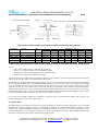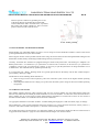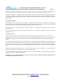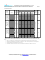
1
INSTALLATION MANUAL
For crystalline solar photovoltaic modules
“According with IEC61215 edition 2 & IEC61730 standards”
CHANGZHOU TRINA SOLAR ENERGY COMPANY LIMITED
Address: No.2 Trina Road, Trina PV Park, New District, Changzhou, Jiangsu, P.R. China
Website: http://www.trinasolar.com (NYSE:TSL) E-mail:[email protected] Tel: 0086-519-88227799
1/11
CHANGZHOU TRINA SOLAR ENERGY CO.,LTD
INSTALLATION MANUAL FOR CRYSTALLINE SOLAR PHOTOVOLTAIC MODULES
1.
Rev.G
INTRODUCTION
Trina Solar Energy Company Limited has a long history of successful innovation within the solar industry. The company was
founded in 1997 and has made significant investments in research and development, creating over 60 patents.
The company has several fully integrated product lines, including ingots, casting, wafers, cells, Mono and Multicrystalline
Silicon Solar Photovoltaic (SPV) modules. Trina products are exported to overseas markets. With an experienced
international management team and a strong reputation for innovation, Trina Solar supplies the highest quality SPV modules
in a range of sizes designed to meet the requirements of the most demanding energy and power users worldwide.
2.
POWER MODULE
Trina Solar Photovoltaic modules consist of a series of electrically interconnected crystalline silicon solar cells, which are
permanently encapsulated between a tempered glass superstrate and substrate. The entire laminate is secured within an
anodized aluminum frame for structural strength; ease of installation, and to protect the cells from the most severe
environmental conditions.
3.
APPLICATIONS
Trina solar SPV modules are a highly reliable, virtually maintenance-free, direct current (DC) power source, designed to
operate most efficiently in sunlight. Trina solar series modules are ideal to power remote homes, recreational vehicles, water
pumps, telecommunication systems and many other applications either with or without the use of storage batteries.
4.
PERMIT
Before installing your system, contact local authorities to determine the necessary permitting, installation and inspection
requirements.
5.
DISCLAIMER OF LIABILITY
The installation, handling and use of Trina Solar Crystalline series modules are beyond company control. Accordingly, Trina
Solar does not assume responsibility for loss, damage, injury or expense resulting from improper installation, handling, use or
maintenance.
Trina Solar assumes no responsibility for any infringement of patents or other rights of third parties that may result from use
of the module. No license is granted by implication or under any patent or patent rights.
Trina solar reserves the right to update the product, specifications or this installation Manual without prior notice.
6.
SAFETY PRECAUTIONS
•
•
•
•
•
•
•
•
•
•
•
The SPV modules installation should be carried out by qualified personnel only.
All installation and safety instructions should be understood before attempting to install, wire, operate or maintain
the modules.
Use properly insulated tools and appropriate protective equipment to reduce risk of electric shock.
Do not stand or step on the module.
Do not damage or scratch the front- or backside surfaces of the module.
Never use a module with broken glass or torn substrate. Broken modules cannot be repaired and contact with any
module surface or frame can lead to electrical shock.
Do not disassemble the modules or remove any part of the module.
Never leave modules unsecured.
Protect plug contacts against soiling; do not make any plug connections using soiled plug contacts.
For rooftop installations, the modules should be mounted over a fire resistant covering rated for such an installation.
Do not install or handle modules when they are wet or during periods of high wind.
Address: No.2 Trina Road, Trina PV Park, New District, Changzhou, Jiangsu, P.R. China
Website: http://www.trinasolar.com E-mail:[email protected] Tel: 0086-519-8227799
2/11
CHANGZHOU TRINA SOLAR ENERGY CO.,LTD
INSTALLATION MANUAL FOR CRYSTALLINE SOLAR PHOTOVOLTAIC MODULES
7.
Rev.G
CLIMATE CONDITION
Install the Trina Solar Crystalline series modules in the following conditions:
•
•
•
•
•
Ambient temperature:
Operating temperature:
Storage temperature:
Humidity:
Mechanical Load Pressure:
-40°C to +40°C.
-40°C to +85°C.
-20°C to +40°C.
below 85RH%
below 112.78lb / ft2 (5400Pa)*.
*Note: the mechanical load bearing (include wind and snow loads) of the module is based on the mounting methods.
The professional system installer must be responsible for mechanical load calculation according to the system design.
8.
SITE SELECTION
In most applications, Trina solar SPV modules should be installed in a location where they will receive maximum sunlight
throughout the year. In the Northern Hemisphere, the module should typically face south, and in the Southern Hemisphere,
the modules should typically face north. Modules facing 30 degrees away from true South (or North) will lose approximately
10 to 15 percent of their power output. If the module faces 60 degrees away from true South (or North), the power loss will
be 20 to 30 percent.
When choosing a site, avoid trees, buildings or obstructions, which could cast shadows on the solar photovoltaic modules
especially during the winter months when the arc of the sun is lowest over the horizon. Shading causes loss of output, even
though the factory fitted bypass diodes of the SPV module will minimize any such loss.
Do not install the SPV module near naked flame or flammable materials.
Do not install the SPV module in a location where it would be immersed in water or continually exposed to water from a
sprinkler or fountain etc.
Do not install the SPV module in a marine environment and/or area where salty wind hit directly.
Do not install the SPV module in Corrosive environment, such as corrosive salt area or sulfurous area, etc.
9.
MODULE TILT ANGLE
Trina Solar SPV modules connected in series should be installed at same orientation and angle. Different orientation or angle
may cause loss of output power due to difference of amount of sunlight exposed to the module.
Trina Solar SPV modules produce the most power when they are pointed directly at the sun. For installations where the SPV
modules are attached to a permanent structure, the SPV modules should be tilted for optimum winter performance. As a rule,
if the system power production is adequate in winter, it will be satisfactory during the rest of the year. The module tilt angle
is measured between the solar modules and the ground (Figure 1). Optimal tilting of SPV module is almost the same as the
latitude of installation location.
SUNLIGHT
MODULE
TILT ANGLE
HORIZONTAL
Figure 1. SPV Module Tilt Angle
Address: No.2 Trina Road, Trina PV Park, New District, Changzhou, Jiangsu, P.R. China
Website: http://www.trinasolar.com E-mail:[email protected] Tel: 0086-519-8227799
3/11
CHANGZHOU TRINA SOLAR ENERGY CO.,LTD
INSTALLATION MANUAL FOR CRYSTALLINE SOLAR PHOTOVOLTAIC MODULES
Rev.G
10. Mechanical drawing of SPV module
Frame cross section (long side)
Frame cross section (short side)
Figure2. SPV module Mechanical drawing*
SPV module
type
TSM-***DC01
TSM-***DC03
TSM-***DC05
TSM-***PC03
TSM-***PC05
Cell type
Mono-crystalline-Si
Mono-crystalline-Si
Mono-crystalline-Si
Multi-crystalline-Si
Multi-crystalline-Si
Cell
quantity
6*12
6*8
6*10
6*8
6*10
Dimensions
A*B*C (mm)
1581*809*40
1316*992*46
1650*992*46
1316*992*46
1650*992*46
Installation hole
E*F (mm)
948*754
800*941
990*941
800*941
990*941
Cable length
G (mm)
1000
1000
1000
1000
1000
Frame dimension
H*C*I (mm)
8*40*40
11*46*38
11*46*38
11*46*38
11*46*38
Table 1: SPV module installation mechanical dimensions
*Note:
− SPV module TSM-***DC01 is used here as an example.
− Where “***” is the rated power of the related SPV module.
11. MOUNTING AND NOTES
Systems should be installed by qualified professionals only. The process involves electricity and can be dangerous if the
installing personnel are not familiar with the appropriate safety procedures.
The modules are qualified for application class A: Hazardous voltage (IEC 61730: higher than 50V DC; EN 61730: higher
than 120V), hazardous power applications (higher than 240W) where general contact access is anticipated (Modules qualified
for safety through EN IEC 61730-1 and -2 within this application class are considered to meet the requirements for Safety
Class II)”
Do not use modules of different configurations in the same system. When the modules connect in series, the voltage of the
string cannot exceed the max system voltage, as reference the maximum number of modules (N) can be easily calculated by
dividing the Maximum System Voltage of the modules by the respective Voc value of the module. When designing the SPV
Address: No.2 Trina Road, Trina PV Park, New District, Changzhou, Jiangsu, P.R. China
Website: http://www.trinasolar.com E-mail:[email protected] Tel: 0086-519-8227799
4/11
CHANGZHOU TRINA SOLAR ENERGY CO.,LTD
INSTALLATION MANUAL FOR CRYSTALLINE SOLAR PHOTOVOLTAIC MODULES
Rev.G
system, please always take into consideration the variation of the voltage under different temperatures (please check the
respective temp. coefficients of the modules, the Voc of the modules will be rise when the temperature drops);
For example: with TSM-190DC01 modules (Max. System voltage is 1000V) the maximum series modules configuration
number should NEVER can exceed N= 17 (1000V/56.22V = 17.8), taking into consideration the possible variation of the
voltage due to the lowest temperature in winter at specified location can reach -40℃.
When SPV modules connect in series, the voltage output of the whole string will be equal to the sum of all modules; when
the SPV modules connect in parallel, the output current will be equal to the sum of each branch current. We suggest that
every series SPV module string should be fused prior to be connected with other strings. Please refer to the applicable
regional and local codes for additional fuse requirements. When necessary, please install blocking diodes to protect SPV
module or SPV system been damaged by reverse current.
The module frame is made of anodized aluminum, and therefore corrosion can occur if the module is subject to a salt water
environment with contact to a rack of another type of metal (Electrolysis Corrosion). If required, PVC or stainless steel
washers can be placed between the SPV module frame and support structure to prevent this type of corrosion. Module
support structures that are to be used to support SPV modules at correct tilt angles should be rated for wind and snow loads
and comply with local and civil codes prior to installation.
Trina Solar SPV modules can be mounted using the following methods:
(Note: All installation methods herein are only for reference, and Trina solar will not provide related BOS components, the
system installer or trained professional personnel must be responsible for the PV system’s design, installation, and
mechanical load calculation and security of the system.)
−
−
−
Using corrosion-proof screws (M8) in the existing installing holes in the module frame.
Using suitable module clamps on the long side of the module frame to mount the modules (“portrait orientation”)
Using suitable module clamps on the short side of the module frame to mount the modules (“landscape orientation”)
1) Screw fitting: The frame of each module has 4 mounting holes (Length* Width: 12mm*9mm) used to secure the
modules to supporting structure. The module frame must be attached to a mounting rail using M8 corrosion-proof screws
together with spring washers and flat washers in four symmetrical locations on the SPV module. The applied torque
should be approximately 8 Newton-meters. Please find detailed mounting information in the below illustration:
Mounting rail
M8 screw
4-φ9*12 installation hole
Washer
Mounting rail
Nut
Cross section A-A enlarged
Figure3. SPV module installed with Screw fitting method*
Address: No.2 Trina Road, Trina PV Park, New District, Changzhou, Jiangsu, P.R. China
Website: http://www.trinasolar.com E-mail:[email protected] Tel: 0086-519-8227799
5/11
CHANGZHOU TRINA SOLAR ENERGY CO.,LTD
INSTALLATION MANUAL FOR CRYSTALLINE SOLAR PHOTOVOLTAIC MODULES
module type
Cell type
Cell quantity
TSM-***DC01
TSM-***DC03
TSM-***DC05
TSM-***PC03
TSM-***PC05
Mono-crystalline
Mono-crystalline
Mono-crystalline
Multi-crystalline
Multi-crystalline
6*12
6*8
6*10
6*8
6*10
Dimensions
A*B*C (mm)
1581*809*40
1316*992*46
1650*992*46
1316*992*46
1650*992*46
Rev.G
Installation hole
E*F(mm)
948*754
941*800
990*941
990*941
990*941
Table 2: SPV module installation mechanical dimensions
*Note:
− SPV module TSM-***DC01 is used here as an example.
− Where “***” is the rated power of the related SPV module.
2) Clamp fitting (portrait orientation): Use a certain number of clamps to fix the modules on the mounting rail. The module
clamps should not come into contact with the front glass and must not deform the frame. Be sure to avoid shadowing
effects from the module clamps. The module frame is not to be modified under any circumstances. When choosing this
type of clamp-mounting method, please be sure to use at least four clamps on each module, two clamps should be
attached on the long sides of the module. Depending on the local wind and snow loads, additional clamps may be
required to ensure the module can bear the load. The applied torque should be about 8 Newton-meters. Please find
detailed mounting information in the below illustration:
The movement of the mounting rail and the clamps center
line are recommended to be within the black arrow area.
Please find data J&K from Table 3 according to the
module type.
Clamp
Fringe modules installation
Mounting rail
Clamp
Frame (long side)
Middle modules installation
A-A
Mounting rail
M6 screw
Figure4. SPV module installed at portrait orientation with Clamp fitting method *
Address: No.2 Trina Road, Trina PV Park, New District, Changzhou, Jiangsu, P.R. China
Website: http://www.trinasolar.com E-mail:[email protected] Tel: 0086-519-8227799
6/11
CHANGZHOU TRINA SOLAR ENERGY CO.,LTD
INSTALLATION MANUAL FOR CRYSTALLINE SOLAR PHOTOVOLTAIC MODULES
module type
TSM-***DC01
TSM-***DC03
TSM-***DC05
TSM-***PC03
TSM-***PC05
Cell type
Mono-crystalline-Si
Mono-crystalline-Si
Mono-crystalline-Si
Multi-crystalline-Si
Multi-crystalline-Si
Cell
quantity
6*12
6*8
6*10
6*8
6*10
A*B
1581*809
1316*992
1650*992
1316*992
1650*992
J
50
50
50
50
50
K
417
358
430
358
430
Dimensions (mm)
M
N
10
14
12
14
12
14
12
14
12
14
Rev.G
O*
P*
0.5~2
0.5~2
0.5~2
0.5~2
0.5~2
2.5~3
2.5~3
2.5~3
2.5~3
2.5~3
Table 3: Mechanical dimensions when modules installed at portrait orientation with Clamp fitting method
*Notes:
−
−
−
−
SPV module TSM-***DC01 is used here as an example.
Where “***” is the rated power of the related SPV module.
Dimension “O” represents the distance between clamp and frame.
Dimension “P” represents the thickness of clamp.
3) Clamp fitting (landscape orientation): Use a certain number of clamps to fix the modules on the mounting rail. The
module clamps should not come into contact with the front glass and must not deform the frame. Be sure to avoid
shadowing effects from the module clamps. The module frame is not to be modified under any circumstances. When
choosing this type of clamp-mounting method, please be sure to use at least four clamps on each module, two clamps
should be attached on the short sides of the module. Depending on the local wind and snow loads, additional clamps may
be required to ensure the module can bear the load. The applied torque should be about 8 Newton-meters. Please find
detailed mounting information in the below illustration:
Clamp
Mounting rail
The movement of the mounting rail and the clamps center
line are recommended to be within the black arrow area.
Please find data J&K from Table 4 according to the
module type
Address: No.2 Trina Road, Trina PV Park, New District, Changzhou, Jiangsu, P.R. China
Website: http://www.trinasolar.com E-mail:[email protected] Tel: 0086-519-8227799
7/11
CHANGZHOU TRINA SOLAR ENERGY CO.,LTD
INSTALLATION MANUAL FOR CRYSTALLINE SOLAR PHOTOVOLTAIC MODULES
Fringe modules installation
Clamp
Frame (short side)
Mounting rail
B-B
Rev.G
Middle modules installation
M6 screw
Figure5. SPV module installed at landscape orientation with Clamp fitting method *
module type
TSM-***DC01
TSM-***DC03
TSM-***DC05
TSM-***PC03
TSM-***PC05
Cell type
Mono-crystalline-Si
Mono-crystalline-Si
Mono-crystalline-Si
Multi-crystalline-Si
Multi-crystalline-Si
Cell
quantity
6*12
6*8
6*10
6*8
6*10
A*B
1581*809
1316*992
1650*992
1316*992
1650*992
J
50
50
50
50
50
K
200
200
200
200
200
Dimensions (mm)
M
N
10
14
12
14
12
14
12
14
12
14
O*
P*
0.5~2
0.5~2
0.5~2
0.5~2
0.5~2
2.5~3
2.5~3
2.5~3
2.5~3
2.5~3
Table 4: Mechanical dimensions when modules installed at portrait orientation with Clamp fitting method
*Notes:
−
−
−
−
SPV module TSM-***DC01 is used here as an example.
Where “***” is the rated power of the related SPV module.
Dimension “O” represents the distance between clamp and frame.
Dimension “P” represents the thickness of clamp.
Clearance between the module frame and mounting surface may be required to prevent the junction box from touching the
surface and to circulate cooling air around the back of the module.
The modules are not designed for integrating mounting as part of a roof or wall unless a special mounting structure will be
used to ensure the building’s safety. The mounting design may have an impact on the system’s fire resistance. If the modules
are to be installed on the roof or wall of a building, the fire resistance of roof covering or wall should be rated for the
application. In this case, the standoff method or the rack method is recommended. The modules are supported parallel to
surface of the building wall or roof. Clearance between the module frames and surface of the wall or roof is required to
prevent wiring damage and to allow air to circulate behind the module. The recommended stand-off height is 115mm. Do not
mount SPV modules in such way that the drain holes of SPV module are blocked.
Do not step on the module. Though SPV modules are strong, the glass can break (and the module will no longer work
properly) if dropped or hit by tools or other objects.
12. GROUNDING
All module frames and mounting racks must be properly grounded in accordance with the appropriate respective national
electrical code. Proper grounding is achieved by connecting the module frame(s) and structural members contiguously one to
another using a suitable grounding conductor. The grounding conductor or strap may be copper, copper alloy, or other
material acceptable for use as an electrical conductor per respective National Electrical Codes. The grounding conductor must
then make a connection to earth using a suitable earth ground electrode.
Address: No.2 Trina Road, Trina PV Park, New District, Changzhou, Jiangsu, P.R. China
Website: http://www.trinasolar.com E-mail:[email protected] Tel: 0086-519-8227799
8/11
CHANGZHOU TRINA SOLAR ENERGY CO.,LTD
INSTALLATION MANUAL FOR CRYSTALLINE SOLAR PHOTOVOLTAIC MODULES
Rev.G
Attach a separate conductor as grounding wire to one
of the 4mm diameter grounding holes marked 'GR'
on the module frame with a set of M4 screw, cup washer,
flat washer, tooth washer, and M4 nut . This is to ensure
positive electrical contact with the frame.
Figure 6. Schematic drawing
for SPV module grounding
13. BYPASS DIODES AND BLOCKING DIODES
Partial shading of an individual module can cause a reverse voltage across the shaded SPV module. Current is then forced
go through the shaded area by the other modules.
When a bypass diode is wired in parallel with the series string, the forced current will flow through the diode and bypass the
shaded SPV module, thereby minimizing module heating and array current losses.
Currently, Trina Solar SPV modules are equipped with bypass diodes in the junction box. The diode type is 10SQ050(for
RenHe junction box)or F1200D (for Tyco junction box 2-1394723-1& 1-1394723-8) or SL1010 (for Tyco junction box
1740699-6) or SL1515 (for Tyco junction box 1740971-1). Do not try to open the junction box to change the diodes even if
it malfunctions. This should be done by qualified personnel only.
In a system that uses a battery, blocking diodes are typically placed between the battery and the SPV module output to
prevent battery discharge at night.
Diodes that are used as blocking diodes must have a:
− Rated Average Forward Current [IF(AV)] above the maximum system current at the highest module operating
temperature.
− Rated Repetitive Peak Reverse Voltage [VRRM] above the maximum system voltage at the lowest module operating
temperature.
14. WARNING AND NOTES
SPV modules generate electricity when exposed to light. An array of many modules can cause lethal shocks and/or burn
hazards. Only authorized and trained personnel should have access to the modules. To reduce the risk of electrical shock or
burns, modules may be covered with an opaque material during installation to avoid shocks or burns. Do not touch live
terminals with bare hands. Use insulated tools for electrical connections.
Use appropriate methods to mount SPV modules. A module falling from high place could cause death, injury or damage.
SPV modules have a pair of male and female waterproof connectors. For a series electrical connection, connect positive (+)
connector of first SPV module to the negative (-) connector of the following module.
Do not short the positive and the negative of a single SPV module. Do not disconnect under load. Be sure connectors have
no gap between the insulators. A gap can cause fire hazard and/or danger of an electrical shock.
Address: No.2 Trina Road, Trina PV Park, New District, Changzhou, Jiangsu, P.R. China
Website: http://www.trinasolar.com E-mail:[email protected] Tel: 0086-519-8227799
9/11
CHANGZHOU TRINA SOLAR ENERGY CO.,LTD
INSTALLATION MANUAL FOR CRYSTALLINE SOLAR PHOTOVOLTAIC MODULES
Rev.G
Artificially concentrated sunlight should not be shown on the SPV module. The electrical characteristics are indicated value
of Pmax under standard test conditions (Irradiance of 1000W/m2, AM 1.5 spectrum, and cell temperature of 25°C).
Under normal conditions, a solar photovoltaic module is likely to produce more current and/or voltage than reported under
standard test conditions. Accordingly, the value of Isc and Voc marked on this module should be multiplied by a factor of
1.25 when determining component voltage ratings, conductor current ratings, fuse sizes, and sizes of controls connected to
the SPV output.
15. MODULE WIRING
Each module has two 4mm2 diameter type standard 90°C sunlight resistant output cables each terminated with plug & play
connectors. This cable is suitable for applications where wiring is exposed to the direct rays of the Sun. We recommend that
all wiring and electrical connections comply with the appropriate national electrical code.
For field connections, use the minimumφ4mm2 diameter copper wires insulated for a minimum of 90°C and Sunlight
resistant as well.
The minimum and maximum outer cable diameters of the cable are 5 to 7mm. Refer to table 5 for the maximum electrical
rating of series fuse.
16. MAINTENANCE
Under most weather conditions, normal rainfall is sufficient to keep the SPV module glass surface clean. If dust or dirt
build-up becomes excessive, clean the glass only with a soft cloth using mild detergent and water. Do not clean the modules
with cold water during the warmer hours of the day in order to avoid creating any thermal shock that maybe damage the
module.
Use caution when cleaning the back surface of the module to avoid penetrating the substrate material. SPV Modules that are
mounted flat (0° tilt angle) should be cleaned more often, as they will not ''self clean'' as effectively as modules mounted at a
15° tilt or greater. At least once a year it is recommended the checking the tightness of terminal screws and the general
condition of the wiring. Also, check to be sure that mounting hardware is tight. Loose connections will result in damage for
array.
Changed SPV modules must be the same type. Do not touch the live parts of cables and connectors. Use appropriate safety
equipment (insulated tools, insulating gloves, etc.) when handling modules.
Cover the front surface of SPV modules by an opaque or other material when repairing. The SPV modules when exposed to
sunlight generate high voltage and are dangerous.
WARNING: For any electrical maintenance, the PV system must first be shut down. Improper maintenance can
cause lethal electric shock and/or burns.
Address: No.2 Trina Road, Trina PV Park, New District, Changzhou, Jiangsu, P.R. China
Website: http://www.trinasolar.com E-mail:[email protected] Tel: 0086-519-8227799
10/11
CHANGZHOU TRINA SOLAR ENERGY CO.,LTD
INSTALLATION MANUAL FOR CRYSTALLINE SOLAR PHOTOVOLTAIC MODULES
Rev.G
OpenCircuit
Voltage
VOC(V)
ShortCircuit
Current
ISC(A)
4.60
42.8
5.15
35.6
4.65
43.2
5.20
170±3%
35.8
4.76
43.6
5.25
175±3%
36.2
4.85
43.9
5.30
180±3%
36.8
4.90
44.2
5.35
TSM-185DC01
185±3%
37.5
4.95
44.5
5.40
TSM-190DC01
190±3%
37.8
5.03
44.8
5.45
TSM-165#C03
165±3%
23.8
6.95
29.0
7.60
TSM-170#C03
170±3%
24.0
7.10
29.2
7.72
175±3%
24.2
7.25
29.4
7.82
180±3%
24.4
7.38
29.6
7.95
185±3%
24.7
7.50
29.8
8.08
TSM-180DC01
TSM-175#C03
TSM-180#C03
TSM-185#C03
15.50
TSM-175DC01
1316×992×46
TSM-170DC01
15.60
34.9
165±3%
1581×809×40
160±3%
TSM-165DC01
25.0
7.60
30.0
8.20
195±3%
25.2
7.74
30.2
8.30
TSM-200#C03
200±3%
25.4
7.86
30.4
8.40
TSM-200#C05
200±3%
27.2
7.36
36.0
8.00
TSM-205#C05
205±3%
27.6
7.43
36.1
8.05
TSM-210#C05
210±3%
28.1
7.48
36.2
8.08
TSM-215#C05
215±3%
28.5
7.55
36.4
8.13
220±3%
29.0
7.60
36.8
8.15
225±3%
29.4
7.66
36.9
8.20
230±3%
29.8
7.72
37.0
8.26
TSM-235#C05
235±3%
30.1
7.81
37.1
8.31
TSM-240#C05
240±3%
30.4
7.89
37.2
8.37
TSM-245#C05
245±3%
30.7
7.98
37.3
8.47
TSM-250#C05
250±3%
31.0
8.06
37.4
8.55
TSM-220#C05
TSM-225#C05
TSM-230#C05
19.50
190±3%
TSM-195#C03
TSM-190#C03
Max-System
Voltage
(VDC)
MaxPower
Current
IPm(A)
TSM-160DC01
1650×992×46
Silicon SPV Module
(Multi- & Mono-Silicon)
(Multi- & Mono-Silicon)
72pcs 125×125mm
Monocrystalline
48pcs 156×156mm
SPV Module
60pcs 156×156mm
SPV Module
MaxPower
Pm(W)
MaxPower
Voltage
VPm(V)
MaxSeries
Fuse
(A)
9.0
IEC61215 / IEC61730:1000VDC
Model
Series
Electrical Performance @ STC
Weight
(kg)
Module
Dimensions
(mm)
17. SPECIFICATIONS:
14.0
14.0
Table 5: Electrical and Mechanical Specifications (For IEC61215 & IEC61730 certificated Module types only)
Notes:
−
−
−
−
Where “#” could be D or P, D represents mono-crystalline silicon while P for multi-crystalline silicon.
Standard Test Condition(STC) of Irradiance of 1000W/m²,AM1.5 Solar Spectrum & 25℃cell temperature
Nominal Operating Cell Temperature (NOCT):47±2℃
Temperature coefficient of Current is 0.05%/ºK, Temperature coefficient of Voltage is -0.35%/°K.
Address: No.2 Trina Road, Trina PV Park, New District, Changzhou, Jiangsu, P.R. China
Website: http://www.trinasolar.com E-mail:[email protected] Tel: 0086-519-8227799
11/11
CHANGZHOU TRINA SOLAR ENERGY CO.,LTD
INSTALLATION MANUAL FOR CRYSTALLINE SOLAR PHOTOVOLTAIC MODULES
文件名称:
Title:
晶体硅太阳能组件安装手册 (For IEC61215ed II&IEC61730 standards)
INSTALLATION MANUAL FOR CRYSTALLINE SOLAR PHOTOVOLTAIC
MODULE (For IEC61215ed II&IEC61730 standards)
文件编号:
SPECIFICATION
NO:
文件
版本
REV:
F
PS-M-0013
更新原因和变更点
DESCRIPTION OF CHANGE
在 PS-M-0013 安装说明书 E 版的基础上更新了下面的内容,并将 IEC61215 和
IEC61730 认证的产品单独的做一份安装说明书,沿用 PS-M-0013 的文件编号,
升级版本
编写者:
Original By:
审核:
Checked by
批准:
APP’D By:
刘振阳
徐建美
张臻
1:变更了文件的版面
2: 增加了 DISCLAIMER OF LIABILITY 的内容。
3: 增加了 SAFETY PRECAUTIONS 的内容。
4: 修改了 CLIMATE CONDITION 的内容,并增加了内容注解
5:增加了 SITE SELECTION 中的部分内容
6:增加了 MOUNTING AND NOTES 中关于 classII 的内容,增加了串并联组件
数的内容,增加了使用 clamps 安装时的部分内容
7:修改了 GROUNDING 中的部分内容,变更了图片.
8:增加了 BYPASS DIODES AND BLOCKING DIODES 中关于二极管的型号及
其相关的参数.
9:在 MAINTENANCE 条款中,增加了部分内容
10:在 SPECIFICATIONS 中, 增加了 5w 分档的内容。
11:删去了原有的附件图,并将相关的图纸和尺寸信息分布到各个相关的内容中.
12: 将所有与 UL 认证要求的内容删去或者修改.
G
Rev.G
修正了部分内容有重复的地方
修正部分语法错误
去掉了推荐最大的并联串数为 2 串
增加了推荐在必要时候安装阻流二极管的内容
修改了页脚的电话号码
王双玉
刘振阳
徐建美
备注: 本表仅仅作为内部控制本文件版本和修订历史记录用,不对外发放.
Address: No.2 Trina Road, Trina PV Park, New District, Changzhou, Jiangsu, P.R. China
Website: http://www.trinasolar.com E-mail:[email protected] Tel: 0086-519-8227799
张臻