1
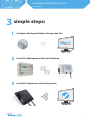
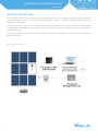
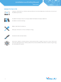
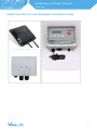
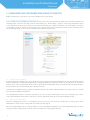
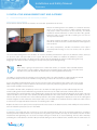
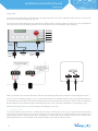
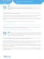
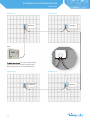
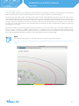
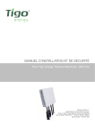
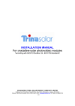
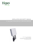
Installation and Safety Manual
TSM_Trinasmart_Installation and Safety Manual_2012_RevB
Installation and Safety Manual
Trinasmart
3 simple steps:
1
Configure the System Before Going to the Site
2
Install the Management Unit and Gateway
3
Install the Optimizers and verify system
2
Installation and Safety Manual
Trinasmart
Table of Contents
Read This First / Safety Instructions .....................................................................................................................................4
Product Description ..................................................................................................................................................................5
Identifying Parts of the Module Optimizer System ........................................................................................................8
Configuring the System Before Going to the Site ..........................................................................................................9
Installing the Management Unit and Gateway ............................................................................................................15
Verifying the System ..............................................................................................................................................................17
Troubleshooting ......................................................................................................................................................................23
Technical Specifications ........................................................................................................................................................25
This symbol is used to indicate
WARNING.
Failure to follow instructions may result in serious hardware failure,
injury, or death.
Use extreme caution when performing this task.
This product complies with CE for Low Voltage Directive
2006/95/EEC
UL 1741 certification- second edition in the U.S. and
Canada
per UL 1741
IP65/ NEMA3R
3
Installation and Safety Manual
Trinasmart
IMPORTANT SAFETY INSTRUCTIONS
SAVE THESE INSTRUCTIONS
• This manual contains important instructions for the installation and maintenance of the Trinasmart
Optimizer System Integrated PV Module and J-Box
• Risk of Electric Shock, Do Not Remove Cover. No user serviceable parts inside. Refer servicing to
qualified service personnel.
• Before installing or using the Trinasmart Optimizer System, please read all instructions and warning
markings on the Trina Solar products, appropriate sections of your inverter manual, photovoltaic (PV)
module installation manual, and other available safety guides.
• Failure to adhere to these instructions may result in injury or death, damage to the system, and
voiding the factory warranty.
• To reduce risk of fire and shock hazard, install this device with strict adherence to National Electric
Code (NEC) ANSI/NFPA 70 and/or local Electrical Codes. When the photovoltaic array is exposed to
light, it supplies a DC voltage to the Trinasmart Module Optimizer. The Trinasmart Optimizer will start
in the “on” state and its output voltage may be as high as the PV module open circuit voltage (Voc)
when connected to the module. The installer should use the same caution when handling electrical
cables from a PV module with or without the Trinasmart Optimizer attached.
• Installation must be performed by trained professionals only. Trina Solar does not assume liability for
loss or damage resulting from improper handling, installation, or misuse of products.
• To avoid risk of electrical shock or fire, do not attempt to disassemble or repair the product.
• Remove all metallic jewelry prior to installing the Trinasmart Module Optimizer to reduce the risk of
contacting live circuitry. Do not attempt to install in inclement weather.
• Do not operate the Trinasmart Module Optimizer if it has been physically damaged. Check existing
cables and connectors, ensuring they are in good condition and appropriate in rating. Do not
operate the Trinasmart Module Optimizers with damaged or substandard wiring or connectors. The
Trinasmart Module Optimizer should be mounted at a minimum of 3 feet above ground.
• Do not connect or disconnect under load. Authorized service personnel should reduce the risk of
electrical shock by pressing the Trinasmart PV-Safe button on the Trinasmart Management Unit
and disconnecting the AC and DC power from the system before attempting any maintenance or
working on any electrical circuits connected to the Module Optimizers. Turning off the Inverter and/
or the Trinasmart Optimizer may not reduce this risk. Internal capacitors within the inverter can
remain charged for several minutes after disconnecting all power sources.
Units are shown in SI (English).
4
Installation and Safety Manual
Trinasmart
PRODUCT DESCRIPTION
For residential, commercial and utility scale photovoltaic solar arrays, the Trinasmart Optimizer System optimizes
power output per-module. The Trinasmart solution also delivers module-level data for operational management and
performance monitoring.
In well-designed large-scale systems, Trinasmart Optimizer systems will return up to 8% incremental power output, while
in residential or commercial systems with partial shading, the system can return up to 20% additional energy throughout
the life of the system.
The product’s low part-count and small footprint has been designed to minimize cost and enhance the reliability of
photovoltaic projects.
Tigo Energy System Architecture
5
Installation and Safety Manual
Trinasmart
TRINASMART’S PV-SAFE FEATURE
When preparing for an installation, check the front panel of the Trinasmart Management Unit (MMU) for the PV-Safe logo.
This is an indicator that the system is equipped with the advanced safety feature.
By pressing the PV-Safe button on the Management Unit or activating the
feature from the web-based console, the Trinasmart Module Optimizers will
attempt to stop voltage from passing to the PV wiring between the Module
Optimizer and the inverter.
Trinasmart PV-Safe depends on the presence of the Management Unit for
successful operation.
IF THE MANAGEMENT UNIT DOES NOT HAVE ACCESS TO AC POWER OR IS
OTHERWISE IMPAIRED, THE PV-SAFE FUNCTION CANNOT BE INITIATED FROM
THE PV-SAFE BUTTON ON THE MANAGEMENT UNIT.
A system configured with the Trinasmart Optimizer solution will attempt to
enter the PV-SAFE mode automatically when the MMU is not visible to the
Optimizers (except when the AC is disconnected at the building main breaker).
Once PV-Safe is activated, always seek active feedback that the modules are disabled by confirming on the Management
Unit display or on the summary page of the web-based software tool; or by testing the DC lines with a voltmeter. When
the PV-Safe button is activated, the MMU will display “PVSAFE PRESSED” and “Requesting ...” to indicate the command has
been sent to the Optimizers.
As the Optimizers are responding, the MMU display will indicate how many have successfully disconnected (ex.“Resp:
15/48”).
Once the system successfully receives acknowledgement from all of the Module Optimizers in the array, the MMU will
display “RESPONDING”. Should the MMU not receive proper response from one or more of the Module Optimizers or
communication has been lost, the display will read “NOT RESPONDING”. If the “NOT RESPONDING” message is present, the
owner or installer must assume that the system is still active and voltage is present as in a standard PV array.
While PV-Safe is meant to enhance system safety, care should always be exercised to avoid high voltage DC wiring
regardless of whether the PV-Safe function is enabled. Trina Solar cannot guarantee complete deactivation of the array
when the PV-Safe button is pressed. Trinasmart PV-Safe must be tested as part of the installation process, and should be
routinely re-tested on an annual basis.
For Trinasmart support, please contact our partner Tigo Energy:
(USA) 1.888.609.8446
(outside the US) +1.408.402.0802
skype: support.tigoenergy
• Plan for Internet connectivity near the location of the Trinasmart Management Unit and purchase Ethernet cable of
appropriate length.
• Confirm that the PV module open circuit voltage (Voc) rating does not exceed the Trinasmart Optimizer’s maximum
input voltage specification.
6
Installation and Safety Manual
Trinasmart
BRING TO THE SITE
A laptop, Smart Phone, or internet connected device to track completion of each step in the On-Site
Installation procedures.
Installation company master user ID/password information if already established
Installation schematic drawing
Phillips and slotted screwdrivers
MC4 type connectors (1 male, 1 female per string)
Permanent marker or label maker.
Determine whether a wired Ethernet connection will be available near the inverter, where the
Trinasmart Management Unit will be placed. If not, order the MMU-ESWIFI from our partner Tigo Energy
for embedded WiFi support.
7
Installation and Safety Manual
Trinasmart
IDENTIFYING PARTS OF THE TRINASMART OPTIMIZER SYSTEM
Trinasmart Module Optimizer (MM-ES)
Management Unit (MMU) and Gateway cable
Gateway
8
Installation and Safety Manual
Trinasmart
1. CONFIGURE THE SYSTEM BEFORE GOING TO THE SITE
Before installing the system on-site, you must configure the system online.
1.1 Configure the System Before Going to the Site
If this is your first time configuring a Trinasmart system, create a new user account by going to the Trinasmart website and
selecting “login”. From the next page, click on the link that says, “New Installer? Sign Up.” A new page will appear where
a new Trinasmart account can be created. Fill in all the fields, and press “Submit” to confirm. An e-mail will be sent to the
e-mail address entered. Click the link provided in the e-mail to activate the Trinasmart account. The link will return to the
Trinasmart login page, use the new user name and password to enter the site.
1.2 Configure New Installation
In order to properly configure the system, please have the 12 digit code from the Management Unit, and all of the Mac IDs
from the Optimizers ready before beginning the configuration process. Optimizer codes can be found on the outside of
the box; this is not recommended if box has been opened. All identification codes are located under the barcode of the
unit and can be entered manually or with a barcode scanner.
From the “My Installations” page, scroll to the bottom and press the “New Installation” button to create a new site. You will
then enter the Configu ration Wizard.
The configuration wizard is a step-by-step process to enter all of the information necessary to configure the system.
Successful completion of the process will create a system, which will show up on the “My Installations” page.
1.3 Verify System Information
Once the configuration process is completed, enter the new site and select the ‘Admin’ tab to verify that all of the
information is correct on the ‘Setting’ and ‘Site Details’ sub-tabs (Fig. 6).
Most of the information in these sections will have been auto-populated during the System Configuration process. Please
verify that all of the information entered is correct, and fill in any missing fields if found.
9
Installation and Safety Manual
Trinasmart
2. INSTALL THE MANAGEMENT UNIT AND GATEWAY
2.1 Trinasmart Management Unit and Gateway Installation
Management Unit Installation
Ensure the AC and DC disconnect switches are in the OFF position for the inverter.
Mount the Management Unit (MMU) in a location that has
access to an AC power source, a stable network connection,
and proper cable connection to the Gateway. The MMU
should be mounted between 3 and 5 feet above the ground.
Mounting tabs are provided for installing on uni-strut or
directly to a wall surface.
The power cord for the MMU is provided with the system kit
and will be connected to the terminal within the Management
Unit enclosure.
For safety compliance, outdoor installations also require
weatherproof housing be used to enclose the AC power
adapter.
The Trinasmart Management Unit includes an external, weather-proof Ethernet port on the bottom surface. Connect
an ethernet cable (not provided) to a live port and then to the MMU. For outdoor installations, install a
weatherproof cap (provided as an option) to the ethernet port by threading the ethernet cable through the cap,
plugging in the ethernet cable, screwing on the cap to the port, and hand tightening.
NOTE:
If the array is going to be placed on a multi-roof surface, or contains more than 60 modules
total, then this system requires more than one Gateway. Please contact the Trina Solar Sales
Department or your distributor for information on ordering additional Gateways.
The MMU is connected to the Gateway using an RS-485 cable. The cable should be a four-conductor, twisted
pair, outdoor-rated wire of at least 18AWG. See Tigo Energy’s website for a list of tested cable options.
Access the MMU communications ports by pressing the latch at the bottom edge of the clear cover of the
MMU and opening the enclosure. Remove the lower cover panel by unfastening the two screws in the bottom
corners with a Phillips head screwdriver.
To install the RS-485 cable, completely remove the nut from the cable gland. Feed the cable through the nut,
and the cable gland into the MMU housing. Attach the four wires to the cable connector terminal, which can be
removed from the circuit board for easier handling. Re-engage the connector into the RS-485 port on the right side. Take
special care NOT to insert this in the Auxiliary RS-485 port. Note the wire colors used on the MMU connection so you can
connect the other end of the wire to the Gateway with the same color configuration. Replace the nut on the cable gland
and hand tighten. If four-conductor twisted pair cable is not available, then outdoor-rated Cat 5 Ethernet cable can be
used instead. See Appendix B for instructions on installing Cat 5 cable.
Replace the lower cover panel, and securely fasten the two screws in the bottom corners with a Phillips head screwdriver.
Close and latch the protective cover in the MMU.
Gateway Installation
A Gateway is provided with the system kit to create the communications link to the Trinasmart Optimizers. Install the
Gateway onto the module frame in the top left corner by pushing the compression clips on the bracket onto the module
metal frame and tightening the set-screw at a torque rating of 15-20 in lbs. to ensure bonding. The face of the Gateway
(including the removable face and the label) should be facing out of the module frame. Confirm that the connectors are
10
Installation and Safety Manual
Trinasmart
facing down.
To connect the RS-485 cable to the Gateway, start by opening the cover of the Gateway. Keep the cover in a clean, safe
Unit
Connection
place Management
to prevent dirt from
getting
on the seal.
Drawing
Insert the RS-485 cable through the left gland on the bottom of the Gateway. Tighten the cable wires into the bulkhead
connector using a small screwdriver. Remove the connector from the circuit board for easier handling
Legend
Tigo Energy
PV-SAFE
24V (-)
24V (+)
Tigo B
Tigo A
Power
Connector
Power
Adaptor
Ethernet
Jack
Gateway
Cable
sehctam gniriw taht erus ekaM
.UMM eht ni lanimret eht
A B
A B
Make sure that the wire connected to each terminal in the Gateway matches the connections in the Management Unit.
If the system has multiple gateways, use the second connection for the outbound cable to the second gateway. Remove
the termination resistor (the small electrical component) from the right four-pin connector in order to wire the outbound
RS-485 cable to the next Gateway. Only the final Gateway in the series connection should have a termination resistor.
When finished, replace the cover of the Gateway. Hand-tighten screws only.
2.2 Gateway Location
The ideal location for the Gateway is underneath one of the central panels in the array so that the distance from any
corner panel to the Gateway is the same. The Gateway comes pre-mounted on a bracket which can be attached to a
module frame with the included clips. When attaching to a module place in the upper left hand corner with antenna
pointing downward. Its exact location can be optimized when you verify the Gateway signal.
11
Installation and Safety Manual
Trinasmart
NOTE:
The Gateway should NOT be located where it may encounter direct exposure to sunlight or rain-fall, or be
placed where the unit could be sitting in pooled water for long periods of time.
Position the Gateway at the center of the module cluster and attach to the upper left-hand corner of a PV
module frame.
2.3 Multiple Gateways
In larger (over 120 modules) or multi-surface PV projects, more than on Gateway will be required to support proper
communications between the Optimizers and the MMU.
To plan the number of Gateways required for the design, partition the system into clustered blocks (up to 120 modules) or
separate sub-arrays. The Module Optimizers in any block should not be more than 50 feet from the Gateway.
Place a Gateway in the physical center of each block or sub-array and connect the Gateways in series, using the second
four-pin connector as the outbound cable from one Gateway to the next. Repeat this process until the final Gateway is
installed.
Keep in mind that only the final Gateway in the series connection should have a termination resistor.
2.4 Power on the Management Unit
IF A SENSOR BOX HAS BEEN ORDERED WITH THE SYSTEM DO NOT PROCEED BEFORE READING SECTION 2.5 SENSOR
INSTALLATION
Plug the MMU power cord into an AC outlet and ensure the MMU has access to the internet. Connect the MMU to the
site’s main AC power circuit (do not use a separate or dedicated power supply).
DO NOT INITIATE “DISCOVERY AND POWER ON” UNTIL ALL OPTIMIZERS HAVE BEEN INSTALLED.
NOTE:
To verify if a connection has been made to the network, the installer can perform a network test directly
from the MMU (see networking troubleshooting in appendix C). If a laptop is available, select the ‘Status’
page to see when the MMU was last updated. If the ‘Last Updated’ section appears in red, then the MMU
has NOT established connection to a viable network.
Once the MMU establishes connection to a network, the MMU will power up, perform configuration checks, download
the latest system software if updates are available, and download the configuration data.
2.5 Sensor Installation (Optional)
If additional sensors are required for the project for measuring light intensity, back-panel temperature, string current or
voltage, these accessories may be ordered with the Trinasmart System at the time of purchase. The sensor accessories are
powered RS-485 devices and are connected through the same RS-485 cable that connects the Gateway.
Install pyranometer, thermocouple(s) or current/voltage sensors within the array as desired. Place the Sensor Box in close
proximity to the sensor(s) within the array. The Sensor Box is provided with a module frame mounting bracket if frame
mounting is desired and appropriate.
The sensor boxes are connected in series, identical to that of a multi-gateway system (see “Multi-Gateway Systems” for
information on how to connect sensor boxes to the RS-485 chain). Be sure to install them before the final (terminated)
Gateway in the circuit.
12
Installation and Safety Manual
Trinasmart
Sub Array 1
Sub Array 2
Gateway
Gateway
MMU
Position the Gateway at the center of the
module cluster and attach to the upper
left-hand corner of a PV module frame.
Sub Array 3
Sub Array 4
Terminated
Gateway
13
Gateway
Installation and Safety Manual
Trinasmart
2.6 Placement of the Caution Labels
Included with the system documentation are three labels which are
essential to indicate that the PV system contains the Trinasmart Optimizer
system with the PV-Safe feature and proper precautions are taken during
the operation of the project.
DC Disconnect Label – contains the PV-Safe logo and states “WARNING:
Press PV-Safe button on the Management Unit before energizing this DC
disconnect. Once turned ON, reactivate the modules from the Management
Unit console.”
Press PV-Safe button on the Management Unit
before energizing this DC disconnect. Once
turned ON, reactivate the modules from the
Management Unit console.
®
Place this label in a visible location on the front surface of the DC Disconnect
unit (typically found next to or integrated into the inverter).
Fuse Combiner Box Label -contains the PVSafe logo and states “WARNING
Press the PV-Safe button on the Management Unit before energizing this
DC breaker or fuse. Once turned ON, reactivate the modules from the
Management Unit console.” Place this label in a visible location on the front
surface of the Fuse Combiner Box (typically found adjacent to the array in
multi-string projects).
Press PV-Safe button on the Management Unit
before energizing this DC breaker or fuse. Once
turned ON, reactivate the modules from the
Management Unit console.
®
AC Disconnect Label - contains the PV-Safe logo and states “WARNING
This PV system is equipped with the Trinasmart Optimizer solution. To deenergize the DC wiring, activate the PV-Safe feature on the Management
Unit prior to opening the AC breaker.” Place this label in a visible location on
the front surface of the AC Disconnect (typically found adjacent to the main
circuit breaker panel).
This PV system is equipped with the Trinasmart
Optimizer solution. To de-energize the DC
wiring, activate the PV-Safe feature at the Management Unit prior to opening the AC breaker.
®
14
Installation and Safety Manual
Trinasmart
3. Verify the System
3.1 Wiring to Adjacent Optimizers
On the first module optimizer of the first string, locate the module designated as “A1” – in the Northwest corner of the PV
array. Locate the positive lead (has a red sleeve) next to the connector. Connect the red (+) output lead from the Module
Optimizer to the extension cabling which connects to the string combiner or directly to the inverter.
Locate the negative lead (has a blue sleeve). Connect the blue (-) output of the “A1” Trinasmart Module Optimizer to the
red (+) output wire of the next Module Optimizer (“A2”).
Connect the blue output of the Trinasmart Module Optimizer of “A2” to the red output lead of the next Module Optimizer
(“A3”).
Continue these steps for all Module Optimizers. An extension cable (not included) may be necessary if two modules are
not physically adjacent to one another.
Connect the blue (-) output wire of the last Module Optimizer to the extension cabling which connects to the string
combiner or directly to the inverter.
A Note on Grounding:
The Trinasmart Module Optimizer is enclosed in a polycarbonate (non-metallic) box that does not require
additional grounding.
3.2 Initiate Discovery and Power On
Once all of the Optimizers have been connected to their modules, return to the Management Unit and initiate the
“Discovery and Power On” command, which will also power on the Optimizers (if they not powered on already). Access
this from the MMU display by selecting “2 Control”, then “2.1 Discover/Pwr”.
The discovery process will initiate communication between the MMU and Optimizers, and verify the Optimizer IDs against
the list of Optimizer IDs in the configuration file for the system. Once the discovery process has been run, the Optimizers
will power on. At this point, the system can produce power, and the voltage from each Optimizer can be as high as the
maximum power voltage of its PV module. The discovery process will take approximately 15 minutes for each Gateway.
The MMU screen will display the status of the system during discovery:
Message
Description
“Find Gateways…”
Searching for Gateways
“Found: X/Y”
Found X Gateways out of Y total Gateways
“Gateways: OK”
Correct number of Gateways found, and all Gateways are functional
“Channel Check…”
Verifying radio channel for Gateways
“Assign X/Y”
Assigning Maximizer X out of Y total Maximizers
“Step[X/Y]: P%”
Each step corresponds to the discovery process of a Gateway (Y total
Gateways), with the percent complete indicated of each step.
The percent completed will reset each time a new Maximizer is discovered
“Found X/Y”
Found X Maximizers out of Y total; still processing
“Done X/Y”
Discovery process is finished. X Maximizers were found and assigned out of
Y Maximizer in configuration
15
Installation and Safety Manual
Trinasmart
3.3 Verify Gateway Signal
Locate the MMU display to aid in placement of the Gateway. If the Gateway is placed in a location that is not ideal for
stable communication with the Trinasmart Optimizers, two messages will appear on the MMU display.
The first will say “Panel Not Comm.” and will provide a count of how many Optimizers out of the total in the array are not
communicating with the Gateway (e.g. Panel Not Comm. 3/14). The second will say “Panel Signal Low” and will provide a
count of how many Optimizers out of the total that are already communicating with the Gateway that have weak signal
strength, and thus are unable to communicate effectively with the Gateway. By paying close attention to these warning
messages, the installer can locate the most ideal place for the Gateway to be able to communicate effectively with all of
the Optimizers in the array.
Proactively validate the signal strength by lifting the protective cover on the MMU and selecting the “MENU” button.
Select “1. STATUS”, and then “1.1. PANELS”. Finally, select “1.1.1. SIGNAL”. This part of the MMU menu will display all of the
configured panels in a list with signal strength marked next to each panel. Use the up and down arrows to scroll through
the list. Pressing “ENTER” will allow you to take a new reading of the PV array’s signal strength.
NOTE:
For troubleshooting purposes, the weakest panels are sorted to appear first in the list.
YOU MUST SUCCESSFULLY COMPLETE THIS STEP BEFORE MOVING ON TO THE REST OF THE INSTALLATION
PROCESS.
16
Installation and Safety Manual
Trinasmart
3.4 String Voltage Polarity Check
As with any installation of a PV system, the installer needs to verify polarity and voltage of each string before connecting
them in parallel with one another.
Use MMU display to confirm voltage readings for each of the panels in each string. Lift protective cover on the MMU and
press “MENU”, and then press “ENTER”. Select “1. STATUS”, and press “ENTER”. Next select “1.1. PANELS”, and press “ENTER”.
Scroll down to “1.1.2. VOLTAGE” and press “ENTER”. The display will show a list of all the configured panels in the PV array
with voltages marked next to each panel. Pressing “ENTER” will refresh the screen and provide the most current voltage
readings for all of the panels.
Make a note of any string that has reverse polarity and/or any string that may not have full Voc voltage at this time to
address after the testing the PV-Safe function next.
3.5 Testing the PV-Safe Function
• Depress the latch to open the clear protective cover on the MMU and press the button labeled “PVSafe” on the
Trinasmart Management Unit.
• When the PV-Safe button is activated, the MMU will display “PV-SAFE PRESSED” and “Requesting ...” to indicate the
command has been sent to the Optimizers. As the Optimizers respond, the MMU display will indicate how many have
successfully disconnected (e.g. “Resp: 15/48”).
• Once the system successfully receives acknowledgement from all of the Module Optimizers in the array, the MMU will
display “RESPONDING”.
• Should the MMU not receive proper response from one or more of the Module Optimizers or communication has been
lost, the display will read “NOT RESPONDING”. If this message is present, the owner or installer must assume that the
system is still active and voltage is present as in a standard PV array. Refer to the Troubleshooting section for instructions
on verifying the system communication is operating properly.
• Please ensure safety precautions are always observed in order to avoid contact with solar wiring regardless of the state
of PV-Safe. Trina Solar cannot guarantee that modules are fully deactivated.
NOTE:
This step should be performed at the installation and annually thereafter to ensure that the PV-Safe
function is in good working order. These same steps can be used when activating the feature for system
maintenance or emergency services.
3.6 Correct any Identified Issues
At this time, if any strings have reverse polarity proceed with corrective rewiring of the strings and go back and redo this
step to verify that the issue has been corrected. If the voltage is not as high as expected, this may be an indication that
one or more of the Optimizers in the string is not communicating with the MMU.
This can also be verified from the Summary tab on the MaxiManager web-interface. Grey panels indicate no
communication. If this is the case go back to re-verify the gateway for better communication with all Optimizers in the
array. Proceed to the next step when all Optimizers are communicating with the MMU.
3.7 Check Power Production
The MMU display can be used to verify power production for each panel in the PV array. Lift protective cover on the MMU
and select “MENU”. Select “1. STATUS”, and then “1.1. PANELS”. Scroll down to select “1.1.3. POWER”. The display will show a
list of all the configured panels in the PV array with wattage values marked next to each panel. Pressing “ENTER” will refresh
the screen and display the most current power output readings for all of the panels in the array.
Since PV-Safe has been activated, you must now activate the panels: First Lift the protective cover on the MMU and select
the “MENU”. Scroll down to select “2. CONTROL”. Scroll down to select “2.1. PANELS ON”. Press “ENTER” again to confirm.
17
Installation and Safety Manual
Trinasmart
APPENDIX A
Trinasmart Management Unit Menu
COMMAND
DESCRIPTION
1. Status
1. Panels
Real-time status of each of the connected panels in the system.
1
Signal
All configured solar panels are shown in a list, with signal strength displayed
for each. User can press Up/Down arrows to scroll through the list; and Enter
to take a new reading of signal strength. For quick identification during
troubleshooting, the weakest panels are sorted to appear first in the list.
2
Voltage
Same as Signal, but displays DC voltage of each panel.
3
Power
Same as Signal, but displays how many watts of power each panel is
producing.
2. Date/Time
Clock read-out. Time is automatically set from the Internet connection,
each time the MMU is rebooted. If the Internet connection has yet to been
established, time display will likely be inaccurate.
3.Unit ID
Shows the ID of each management unit, a 12-letter code. This will also be the
MAC address of the Ethernet port (useful for network troubleshooting).
2. Control
1. Discovery
Initiates communication with all Maximizers, and powers them on.
2. Panels ON
Connects power to all solar panels. Use this to turn the system back on, after
having earlier hit the “PVSafe” button to turn the system off.
3. Push Data
Immediately attempts to make another communication to transfer data to
the data center, without having to wait the usual 10 minute period between
communications. Useful for real-time debugging.
4. Restart
Reboots the Management Unit.
3. Network
1. Display IP
Shows the IP address of the Management Unit, on the premise network. Very
useful to determine connectivity.
2. Test
Validates the connection to the data center, without transferring data. Displays
“Success” if the Internet connection is functional.
3. Configure
Configures the MMU’s wired Internet connection. This is a sequence of steps,
where the operator will be asked a series of yes/no questions, and also asked
to enter data if necessary. Indicating “Yes”, when asked “Automatic IP?”, will use
DHCP - the easiest and best configuration for most connections.
4. Set Proxy
Configures the use of a proxy server for HTTP requests when transferring data
to the data center. Not recommended, unless necessary to get through a
corporate firewall.
5. Set Default
Sets the management unit to a temporary static IP address of 192.168.0.15.
Rarely useful, except for testing during network troubleshooting.
6. Renew
Resets the IP address of the MMU. If “Automatic IP” is chosen, uses DHCP to
request another IP address. This should be done after making any changes to
the premise router configuration, or any changes to the Ethernet connection.
7. Alt IP
Use only when requested by support staff for troubleshooting.
18
Installation and Safety Manual
Trinasmart
APPENDIX B:
INSTALLING CAT 5 CABLE BETWEEN THE MMU AND GATEWAY
If four-conductor twisted-pair cable is not available, then the MMU-Gateway connection can be wired with Cat 5 Ethernet
wire. The data feed (leads A and B on the MMU and Gateway terminal blocks) must be connected to the same twisted pair.
See the table for instructions on connecting the cable:
Gateway/MMU Terminal Label
Signal
Cat 5 Cable Color(s)
A
RS485 (+)
Blue/White Stripes
B
RS485 (-)
Blue
+
+24v
Orange
Green
Brown
-
GND
Orange/White Stripes
Green/White Stripes
Brown/White Stripes
19
Installation and Safety Manual
Trinasmart
APPENDIX C: TROUBLESHOOTING
WARNING.
Servicing Instructions: “Warning - These servicing instructions are for use by qualified
personnel only.
To reduce the risk of electric shock, do not perform any servicing other than that
specified in the operating instructions.”
WARNING.
Troubleshooting the PV array or the Trinasmart Module Optimizers should be
completed only by qualified personnel. Do not disconnect PV connectors under load.
WARNING.
The Module Optimizers contain no user-serviceable parts. Do not attempt to open
the enclosure. Tampering with or opening the Module Optimizer will void the factory
warranty. See warranty for instructions on obtaining service.
Troubleshooting the Gateway connection
The Gateway has an LED light at the bottom of the unit, which shows the status of the Gateway. This is useful for
troubleshooting problems with the system communications. See the table below for the meaning of each light pattern:
Color pattern
Gateway Status
No color
Not powered from MMU
Solid blue
Powered, but not communicating
Blue and yellow (blinking)
Powered and communicating with Maximizers
Discovery Process Error Messages
If error messages are displayed during the discovery process, see the table below for descriptions of the problem.
Error message
Description
“Err#1: X/Y”
MMU has only found X Gateways Check Gateway cable connections, call Tigo Energy
(was expecting to find Y)
Support if problems persist
Corrective action
“Err#3: XXXX”
“Err#4: XXXX”
“Err#6: GW_XXXX err”
“Err#7: GW_XXXX err”
“Err#6: GW_XXXX err”
“Err#10: GW_XXXX err”
“Err#11: MM pos”
“Err#12: GW_XXXX err”
“Err#13: GW_XXXX err”
Failed Gateway communication
during discovery, cannot find
Gateway XXXX
Check Gateway cable connections, call Tigo Energy
Support if problems persist
“Err#5: Chnl err”
Could not find free channel for
Gateway
Contact Tigo Energy Support
20
Installation and Safety Manual
Trinasmart
Troubleshooting the Network Connection To the Trinasmart Management Unit
To verify the integrity of the MMU network connection, start by lifting the protective cover on the MMU and press the
“MENU” button – then press “ENTER”. Use the down arrow to select “3. Network”– then press “ENTER”. Scroll to “3.2. Test” –
then press “ENTER”.
While the test is running, the screen will display a variety of messages to indicate the status of the network test:
Message
Description
Corrective action
“Connecting…”
Trying to access Tigo Energy’s
server
N/A
“Success.”
MMU has successfully accessed
the server
N/A
“Error: checking”
MMU could not connect to
the Tigo Energy server, and is
diagnosing cause of problem
N/A
“Cable unplugged”
No physical cable detected
Check cable connection and re-initiate network test
“Check proxy svr”
MMU is configured to access the Verify proxy settings on MMU. Verify proxy server
web via HTTPS proxy, and server allows access to https://datacenter.tigoenergy.com.
is not cooperating
Re-initiate network test
“No default GW”
Missing default gateway. Either
DHCP server is not replying, or
static configuration entry is not
present
Verify physical connection at router. Verify
configuration of router allows MMU to access network.
Re-initiate network test
“Cannot ping GW”
Default gateway did not
respond to ping. May not be a
problem, depending on router
configuration
Verify physical connection of cabling at router and reinitiate network test
“Cannot ping DNS”
Global public DNS server (8.8.8.8)
is not responding. Indicates
possible inability to connect
Check internet connection and re-initiate network test
to internet. May not be a
problem, depending on router
configuration
“Cannot ping Tigo”
Cannot exchange ICMP packets
with Tigo Data Center. May not
be a problem, depending on
router configuration
21
Contact Tigo Energy’s Customer Support team at
+1.888.609.8446 or [email protected]
Installation and Safety Manual
Trinasmart
To check the local network for issues:
1. Check with the network administrator to make sure the network provides the IP address automatically to computers
that connect to it. The MMU is configured to obtain an IP address from the network automatically through a DHCP
server. If the network requires a static IP address see section below.
2. Check if the network cable is functional. If the cable is working and the MMU is connected to an active network switch
through the cable, the LED should blink at the switch port connection.
3. Check the network connection with a laptop computer. Verify the network connection to the MMU by disconnecting
the network cable from the MMU and connecting it to a laptop. If the laptop can access the web but the MMU cannot,
contact the Tigo Energy support hotline.
Setting up a Static IP address
1. Contact the network administrator and obtain the following information:
Static IP address assigned to the MMU: ........................................................................................................................................................................................
Subnet Mask: .................................................................................................................................................................................................................................................
Default gateway: ........................................................................................................................................................................................................................................
Preferred DNS server: ...............................................................................................................................................................................................................................
Alternate DNS server: ...............................................................................................................................................................................................................................
2. Bring this information and locate the Trinasmart Management Unit. Depress the latch to open the clear protective cover
on the MMU and press the “MENU” button – then press “ENTER”. Scroll to “3. Network” – then press “ENTER”. Scroll to “3.3.
CONFIGURE”- then press “ENTER”.
3. The display will read “ARE YOU SURE?” AND “Y=ENTER, N=MENU”. To proceed press “ENTER”. The display will read
“AUTOMATIC IP?” AND “Y=ENTER, N=MENU”. To proceed press “MENU”. Then the display will read “IP ADDRESS:” AND
“000.000.000.000”. Notice the cursor is under the left most zero. Use the scroll up and down keys to change the value of
the number. Use the “ENTER” key to move right and the “MENU” key to move left. When the cursor is on the right most
digit, you can move to the next input screen by pressing “ENTER”.
4. The next entry field will read “SUBNET MASK” AND AGAIN “000.000.000.000”. Use the four keys as before to move and
change the number values.
5. The next entry field will read “DEFAULT GATEWAY” AND AGAIN “000.000.000.000”. Use the four keys as before to move
and change the number values.
6. The next entry field will read “PREFERRED DNS SERVER” AND AGAIN “000.000.000.000”. Use the four keys as before to
move and change the number values.
7. The next entry field will read “ALTERNATE DNS SERVER” AND AGAIN “000.000.000.000”. Use the four keys as before to
move and change the number values.
8. The final field will read “SAVE SETTING?” and “Y=ENTER, N=MENU”. Press “ENTER” to complete the entry of a new static IP
address for the MMU.
Troubleshooting – Optimizer ID
If there is an error with the Optimizer IDs, these can be edited directly through the software interface. From “My
Installations”, click on the project you would like to edit. Then select the “Admin” tab, and the “Site Details” sub-tab. Scroll to
the bottom of this page to find a button labeled “Edit Configuration.” From the edit section, hit “Next” twice. You will now
find yourself on the Optimizer ID page, where you can edit the incorrect IDs. When you are done, click “Save” to save your
changes.
Troubleshooting modules which are not seen by the Trinasmart Management Unit.
If the Trinasmart MaxiManager Software in the “Summary” view shows the module as powered off, when it is expected to
be active:
1. Check that the physical connections between the PV module and the Module Optimizer are complete and secure.
2. Refresh the web browser configuration and check to see whether the panel has refreshed.
3. If the problem persists, determine if the Module Optimizer is out of communication range of the MMU. This can be
determined by the performance of other Module Optimizers in close proximity.
4. If the signal strength is too low, install or reposition the Gateway.
5. Once complete, refresh the browser to check whether the module is now visible and active.
22
Installation and Safety Manual
Trinasmart
Call the Installation support line should problems persist:
(USA) 1.888.609.8446
(outside the US) +1.408.364.0150
CONFORMANCE CERTIFICATION – SAFETY
The Trinasmart Module Optimizer and Management Unit comply with the appropriate sections of the following
International Standards to maintain the CE conformity mark:
• IEC EN60950 Standard for Safety Requirements for Electrical Equipment for Measurement, Control and Laboratory Use.
• IEC EN60529 Degrees of Protection Provided by the Enclosure (IP Code). The enclosure meets or exceeds IP65 and NEMA
3R classification.
FCC Compliance
This equipment has been tested and found to comply with the limits for a Class B digital device, pursuant to part 15 of
the FCC Rules. These limits are designed to provide reasonable protection against harmful interference in a residential
installation. This equipment generates, uses and can radiate radio frequency energy and, if not installed and used in
accordance with the instructions, may cause harmful interference to radio communications. However, there is no
guarantee that interference will not occur in a particular installation.
If this equipment does cause harmful interference to radio or television reception, which can be determined by turning
the equipment off and on, the user is encouraged to correct the interference by one or more of the following measures:
• Reorient or relocate the receiving antenna.
• Increase the separation between the equipment and the receiver.
• Connect the equipment into an outlet on a circuit different from that to which the receiver is connected.
• Consult the dealer or an experienced radio/TV technician for help.
This device complies with Part 15 of the FCC Rules. Operation is subject to the following two conditions: (1) this device
may not cause harmful interference, and (2) this device must accept any interference received, including interference that
may cause undesired operation.
Changes or modifications not expressly approved by the party responsible for compliance may void the user’s authority to
operate the equipment.
23
Installation and Safety Manual
Trinasmart
TECHNICAL SPECIFICATIONS
Mechanical Data
Solar Cells
Multicrystalline 156 × 156mm (6 inches)
Cell Orientation
60 cells (6 × 10)
Module Dimension
1650 × 992 × 40mm (64.95 × 39.05 × 1.57 inches)
Weight
19.5kg (43.0 lb)
Glass
High transparancy solar glass 3.2mm (0.13 inches)
Frame
Anodized aluminium alloy
J-Box
IP 65 rated
Cables / Connector
Photovoltaic technology cable 4.0mm2 (0.006 inches2),
1100mm (39.4 inches), H4
Temperature Ratings
Maximum Ratings
Nominal Operating Cell
Temperature (NOCT)
46°C (±2°C)
Temperature Coefficient of PMAX
- 0.41%/°C
Temperature Coefficient of VOC
- 0.32%/°C
Temperature Coefficient of ISC
0.053%/°C
Operational Temperature
-40~+85°C
Maximum System Voltage
1000VDC (IEC)
600VDC (UL)
Max Series Fuse Rating
15A
Warranty
Packaging Configuration
10 year workmanship warranty
Modules per box: 25 pcs
25 year linear performance warranty
Modules per 40’ container: 650 pcs
(Please refer to product warranty for details)
Module Maximizer J-ES50
Input data
MMJ-ES50
Output Data (DC)
Maximum Power
300W
Maximum Output Power
300W
Maximum Input DC Voltage (VOC)
52V
Maximum Continuous Current
9.5A
VMP Range*
16-48V
Nominal Voltage / Range
variable
Maximum Continuous Current (IMP)
9.5A
Maximum Input Current (ISC)
10A
* VMP = Voltage at maximum power = Maximum power voltage
Mechanical Data
Operating Temperature Range
-30°C +70°C
Cooling
Natural convection
24
APMEA
China
Changzhou
Corporate Headquarters
No. 2 Tianhe Road, Trina PV
Industrial Park, New District,
Changzhou, Jiangsu, 213031
t + 86 519 8548 2008
f + 86 519 8517 6021
e [email protected]
Shanghai
333 North Caoxi Road
CCIG International Plaza
Building B, Offices 1704-1706
Shanghai 200030
e [email protected]
Beijing
48 Dongzhimenwai Street
Oriental Kenzo Office Building,
X-17KL, Dongcheng District,
Beijing 100027
t + 86 10 5817 4080
f + 86 10 5817 4020
e [email protected]
Singapore
Trina Solar (Singapore) Pte Ltd
Three Temasek Avenue
#16-03 Centennial Tower
Singapore 039190
T + 65 6808 1111
F + 65 6835 7225
Japan
Germany
Trina Solar (Japan) Limited
World Trade Center Building
33rd floor, 4-1 2-Chome
Hamamatsu-cho Minato-ku,
Tokyo 105-6133
Trina Solar (Germany) GmbH
Einsteinring 26,
D-85609 Aschheim/München,
t + 81 3 3437 7000
f + 81 3 3437 7001
e [email protected]
Malaysia
Trina Solar (Malaysia) SDN. BHD.
Plot 201, Lebuhraya Kampung Jawa
Bayan Lepas FTZ, Phase 3, 11900
Pulau Pinang
T + 60 4685 2008
Australia
Trina Solar (Australia) Pty Ltd
Macquarie House
LEVEL 13, Office Number 1315
167 Macquarie Street
Sydney NSW 2000
t + 61 2 8667 3088
f + 61 2 8667 3200
e [email protected]
United Arab Emirates
Trina Solar Middle East Ltd
Office #306, Injazat Building,
Mohamed Bin Zayed City,
Abu Dhabi,
P.O Box 135084
t + 971 562047969
e [email protected]
t + 49 89 122 8492 50
f + 49 89 122 8492 51
e [email protected]
Italy
Trina Solar (Italy) Srl
Via Santa Maria Valle 3
20123 Milan
t + 39 02 0068 1521
f + 39 02 0068 1400
e [email protected]
Spain
Trina Solar (Spain) Slu
Paseo de la Castellana 141,
8th Floor,
28046 Madrid,
t + 34 91 572 6576
f + 34 91 572 6621
e [email protected]
United Kingdom
Trina Solar (UK) Ltd
Regus East Midlands Airport
Pegasus Business Park
Herald Way, Castle Donington
Leicestershire
DE74 2TZ
T + 44 1332 638 700
F + 44 1332 638 160
France
Trina Solar Korea Ltd
B1-140, Daewoo Dovile 117
Hap-dong Seodaemun-gu
120-030 Seoul
Europe
Trina Solar (France) SAS
21 Avenue Georges Pompidou
69486 Lyon Cedex 03
Switzerland
European Headquarters
T + 33 (0)4 72 91 30 00
F + 33 (0)4 72 91 30 30
t 02 392 1588
f 02 362 8820
e [email protected]
Trina Solar (Schweiz) AG
Richtistraße 11
8304 Wallisellen Schweiz
North America
Korea
T + 41 43 299 6800
F + 41 43 299 6810
E [email protected]
United States
Trina Solar (U.S.) Inc
100 Century Center, Suite 340,
San Jose CA 95112,
USA
t + 1 800 696 7114
f + 1 800 696 0166
e [email protected]
For more info
www.trinasolar.com
APMEA refers to Asia Pacific, Middle East and Africa
Optimized by