1
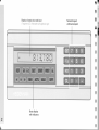
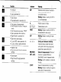
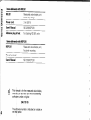
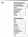
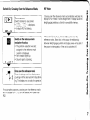
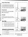
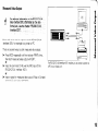
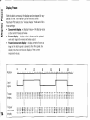
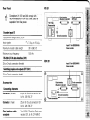
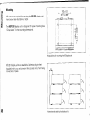
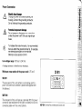
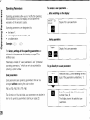
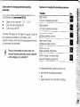
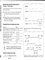
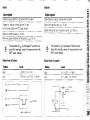
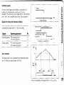
KW
Function
l
l
l
q
q
Set datum
Transfer input value
Leave parameter list
. Select datum
l
Page backwards
l
l
l
l
l
l
l
l
l
l
Indicator
in parameter
REF
Reference mark has been traverseddisplay stores datum points in
nonvolatile memory
Blinking: display is waiting for ENT or
CL to be depressed
in.
Position
values in inches
Cl
Selected
datum point
list
Start series of measurements
Switch display for series of measurementS
Start measured value output “PRINT”
Select parameter after switch-on
Page forward in parameter list
IL2
PRINT
SET
through
l
Decimal point
. Page forward through
Blinking: Display is waiting for ENT to
be dewessed
for data outout
Blinking:
Display is waitinq
for input
values
Abort entry/ clear display
CL plus MOD: select parameter list
CL plus number: select parameter
Algebraic sign
Page backwards
sfmngs
Meaning
Sorting
and tolerance
checking:
measured value smaller than lower
sorting limit/within
the sorting limits I
greater than upper sorting limit
parameter
MINIMAXI
DIFF I ACTL
parameter
START
Series of measurements:
Minimum 1
maximum /greatest difference
(MAX-MIN)
I current measured value
Blinking: Confirm selection or deselect
function
Series of measurements
is running
Blinking: Display is waiting for signal to
start series of measurements
Items delivered
with
ND 281
ND 281
Power
Measured
bench-top
cord
value display unit,
design
3 m IS.9 ftl
ND 281iNDP
Adhesive
plug-in
Items ddivered
feet
with
for stacking
ND 281 units
NDP 281
NDP 281
Power
281
Measured value display unit,
for panel mounting
terminal
User’s Manual
ND 281/NDP
281
@ .“N
This
anual is for the measured value display
units D 281 and NDP 281 with the following
software number or higher:
24611010
The software number
the rear panel.
is indicated
on a label on
Contents
Working
Position
with the ND Display
Encoders
Switch-On,
and Reference
Crossing
Marks
Over the Reference
Datum Setting
Minimum
Sorting
and Tolerance
Display
Error
6
Marks
7
8
Finding
Measured
Units
and Maximum
Values
Checking
9
12
Value Output
13
Freeze
14
Messages
15
Installation
and Specifications
Rear Panel
17
Accessories
17
Mounting
18
Power
Connection
19
Operating
Parameters
List of Operating Parameters
20
22
Linear
25
Encoders
RS-232.WV.24
Switching
Inputs
Distance-To-Go
Specifications
Dimensions
Interface
(X31)
and Outputs
Mode
28
EXT 1x41)
34
39
40
dl
Position
Encoders
and Reference
Marks
The ND 281 and NDP 281 display units are primarily intended
for use with HEIDENHAIN MT length gauges. These length
gauges have one reference mark. The scales of other
photoelectric
linear encoders (see “Linear Encoders”) can
contain one refereence mark or several distance-coded
reference marks.
If there is an interruption of power, the relationship between
the position of the length gauge and the displayed position
value is lost. The reference marks on the position encoders
and the REF reference mark evaluation feature enable the
display unit to quickly re-establish this relationship again when
the power is restored.
When a reference mark is crossed over, a signal is generated
which identifies that position as a reference point. At the
same time, the display unit restores the relationship between
length gauge position and display values which you last
defined by setting the datum.
If the linear encoders
have distance-coded
reference marks,
you only need to traverse a maximum of 20 mm to restore the
datum.
!6
llUillllllnlHllllUlslUlllullllllllllllllllllllulllll,
,
c
Reference marks on linear encoders
Switch-On,
Crossing
Over
the Reference
Marks
(Switch located on rear panel.)
Ella
’ is displayed.
l
Indicator REF is blinking.
REF Mode
Crossing over the reference
eference marks automatically switches the
display to REF mode:le: The last assignment of display values to
Irl
length
syLmm
gauge IJyalllons
ymyyc
positions is stored in nonvolatile memory.
l
evaluation
function.
l
The position value that was last
assigned IO the reference mark
position is displayed.
l
REF indicator lights up.
l
Decimal point is blinking.
Cross over the reference
mark.
For automation purposes, crossing over the reference marks
and the display ENT
CL can be disabled with parameter
P82.
* Press the CL key if you choose not to cross over the
reference marks. Note that, in this case, the relationship
between length gauge position and display value will be lost if
the power is interrupted or if the unit is switched off.
Datum
Setting
The datum setting procedure
assigns a display value to a
known position. With the ND 200 series, you can set two
separate datum points.
There are several ways to set the datum:
9 Enter a numerical value, or
l
Transfer a value from an operating parameter
lsee P79, P86). or
l
By external signal
Without datum setting: unknown assignment of measured valves to
positions
Enter
numerical
value
(here, 5).
1
z
20
You can switch between datums 1 and 2 as desired. Datum 2
can be used, for example, for working with incremental
dimensions.
15
10
5
When you switch back to datum 1, the display unit resumes
display of the MT’s actual position.
0
After datum setting: Assignment of measured values to positions
Finding
Minimum
and
Series of Measurements
Maximum
Values
From
a
After a series of measurements
has been started, the display
transfers the first measured value to the memory for minimum
and maximum values. Every 0.55 ms, the display compares
the current measured value with the memory contents: A new
value is stored if it is greater than the stored maximum value
or smaller than the stored minimum value. At the same time,
the display calculates and stores the difference DIFF between
the current MIN and MAX values.
DisDlav
Meanina
MIN
Minimum
value from the series of measurements
MAX
Maximum
value from the series of measurements
DIFF
Difference
MAX - MIN
ACTL
Current
measured
r
Sews of measurements: The MIN. MAX and DIFF values of an uneven
surface
value
Starting the series of measurements
and selecting
the display
You can start the series of measurements
either by pressing
MOD and selecting the desired display-as
described on the
following pages--or
by external signal over the switching
inputs at the D-sub connection
EXT (X41, see page 34).
When a series of measurements
is started, the internal MlN/
MAX/DlFF memory is reset.
Example: Series of measurements for determining eccentricity e
I10
Starting
a series
of measurements
Select the display
Switching
for a series of
between
MIN. MAX,
DIFF and ACTL displays
It is not possiple to switch between thL displays as
described below if the switching input for external
control of the series of measurements~(pin
6 on
D-sub connection EXT) is active.
As an alternative, you can select the display with operating
parameter P21 (see “Operating
Parameters”).
11;
Indicator
Select the new
until the indicator
display
of a series of
START blinks.
The display now shows the smallest value measured
the current series of measurements.
preselection
Press MOD to start the series of measurements
the display with the indicators.
and select
Operating parameter P86 allows you to define which
is displayed first when MOD is pressed.
indicator
during
Starting
a new series of measurements
The indicator
Ending
START blinks.
a series of measurements
Select
the active indicator
IMIN, ACTL,
Sorting
and Tolerance
Checking
In the sorting and tolerance checking mode, the display unit
compares the displayed value with the programmed
upper
and lower sorting limits. The sorting and tolerance checking
mode is enabled and disabled with operating parameter P17.
Entering sorting
limits
Sorting limits are entered in operating
PlS (see “Operating Parameters”).
Sorting
parameters
P18 and
signals
The indicators and switching outputs at D-sub connection
EXT (X41, see page 34) sort the display value into one of three
classes.
12
Display
Mehning
:
Measured
value is within
c
Measured
value is smaller than lower
z
Measured
value is greater
soning limits
sorting limit
than upper sorting lirrlit
Measured
Value Output
itiQrmati5n
on ma R,S-232-C/y.?4
‘CC311,Jcifpimatigq an;ttw data
form% etc., see the Chapter “R$-232~QV.24,
Interfa~a,~X31)“.
‘:,
r
17j
PC
Measured values can be output over the RS-232.CN.24
interface (X311, for example to a printer or PC.
There are several ways to start measured
l
l
l
value output:
Press MOD repeatedly until the indicator PRINT blinks,
then start measured value output with ENT;
or
Input the command Ctrl B over the RXD input of the
RS-232.CN.24
interface (X31);
or
Input a signal for measured data output (Pulse or Contactl
at the D-sub connection EXT (X41).
The RS-232-CAL24 interface (X31 1 enables you to connect a printer or
a PC to your display unit
Display
Freeze
With the latch command, the display can be stopped for any
period of time. The internal counter remains active.
Parameter P23 selects the “display freeze” mode and offers
three settings:
l
Concurrent
display, no display freeze-the
display value
is the current measured value.
l
Frozen display-display
value is frozen and is updated
with each signal for measured value output.
l
Frozen/concurrent
display-display
remains frozen as
long as the latch signal is present: after the signal, the
display resumes continuous display of the current
measured values.
Error
Messages
Display
c /- /- ,-,,;;;-;-;I;;-
; ;,p
I: I- I- ,-,t- /-,?
,,;,
I-
Disolav
Problem
i-, ,
:
;i ;- ;- ;I;;-
:
:i-,
value has not been output*
The external device is not connected,
DSR signal (only displayed once!)*
Data interface:
format*
,-s-,1LJ,
Last measured
Parity error or wrong
Overflow due to external
P79 too high)
Overflow
triaaer
limit 1
limit 2
setting Mue
Overflow
trigger
;: ;-;-;I;;- ;s
Overflow
lower sorting limit
I.
Overflow
upper sortina limit
i
,j/
I- -
I-,,-
E
y-y
The encoder signal is too weak.
may be contaminated.*
no
Problem
8.
is,
riji
,_
81,
is,
,-,/
,I,?
,I, /
If these errors persist, contact your
HEIDENHAIN service agency.
Check the operating parameters.
If this error persists, contact your
HEIDENHAIN service agency.
transfer
for
Other
error
displays
If all decimal points
great or too small:
)
The scale
8: ,-/-s-t/,_
, ,-/,
I-2
The input frequency for this encoder input
is too high. This can occur when the scale
is moved too fast.”
iI, I : ::
5,:;
Internal counter
overflow*
light up, the measured
Set a new datum
If all sorting signals light up, the upper sorting
smaller than the lower limit:
l
Change operating
To clear error
parameters
l
These errors are important for the attached device. The
error signal ipin 19) at D-sub connection EXT is active.
P18 and/or PI9
messages:
When you have removed
*
value is too
the cause of the error:
Clear the error message
with the CL key.
limit is
Ir
I
16
Rear Panel
ND 231
X41 comply with
VDE 0160, 5.88. for
from line power.
separajion
Encoder input Xl
HEIDENHAIN
flanae
socket. 9-ain
Input signals
-J
Maximum
encoder
cable length
Maximum
input freauencv
7 PAW to 16 vApp
30 m (98.5 fti
100 kHz
RS-232~WV.24 data interface (X31)
25.uin
D-sub connection
Switching
25.pin
(female)
inpufr and outputs EXT WI)
D-sub connection
(male)
Accessories
Connecting
elepwnts
Connector
(femalei
25.pin for D-sub connection
Id:Nr. 249 154 ZY
X41
Connector
(male)
25.pin for D-sub connection
Id:Nr. 245 739 ZY
X31
Data interface
complete
cable
3 m 19.9 it), Spin for D-sub connection X31, Id:Nr. 274 545 01
Mounting
M4 scwvs are required for securing the ND 281 display unit
from below (see illustration at right).
The NDP 281 display unit is designed
“Dimensions”forthemountingdimensions).
for panel mounting
ND 281 display units are stackable. Adhesive
(supplied with your unit) prevent the stacked
moved out of place.
(see
plug-in feet
units from being
r
1
Power
Connection
A
Elyic
shock danger
Unplug the power cord before opening the
housing. Connect the grounding conductor.
Do not interrupt the grounding conductor.
Potential component
A
&
damage
Do not engage or disengage any connections
unless the power is off. Only use original type
fuses.
To incr&se the noi% immunity, it is recommended
that yoi, attach the ground terminal to, for example,
the central ground point of the machine.
(Minimum crws section 6 mm2.t
Line voltage range: 100 Vat to 240 Vat
A voltage selector
Minimum
is therefore
not necessary.
cross section of the power cord: 0.75 mm2
ND 281
The rear panel of this unit contains a connecting jack for a
power cord with Euro connector (power cord supplied with
the delivery).
NDP 281
The rear panel of this unit features a terminal IX511 for power
connection (see illustration to the right). Be careful to wire the
connecting cable with the correct polarity.
NDP 281:Terminalforconnectingthe
powercord
Operating
To access
Parameters
a user parameter
after switching
on the display:
Operating parameters allow you to modify the operating
characteristics
of your ND display unit and define the
evaluation of the encoder signals.
Operating
l
l
l
parameters
are designated
the letter P,
a two-digit parameter
an abbrwation,
number,
by:
and
during
operation:
Tagelm
The factory settings of the operating
parameters
are
indicated in the parameter list (starting on page 221 in
boldface type.
mm
Parameters consist of “user parameters”
and “protected
operating parameters,”
which can only be accessed by
entering a code number.
To go directly
Together:
User parameters
User parameters
changed without
are operating parameters that can be
entering the code number:
mu
PO0 to P30. P50, P51, P79. P86
The functions of the individual user parameters are detailed
the list of operating parameters (starting on page 22).
0
,
Display first user parameter.
in
to a user parameter:
Press and hold CL while entering the first
dIgIt of the parameter numberihere,
I).
”
Code number
parameters
for changing
protected
operating
If you wish to change protected operating parameters,
must first enter the code number 95 148:
l
l
l
Select the user parameter
:K::C:
Enter the code number 95 148.
Confirm entry with ENT.
Functions
parameters
Key
Page forward
in the list of operating
parameters
Page backward
in the list of operating
parameters
::l:&
Once you have entered the code number, the
protected operating parameters remain accessible
until the display unit is switched off
the operating
Function
you
Parameter P30 appears on the display. By paging through the
list of operating parameters you can display--and,
if
necessary, change--each
protected operating parameter and,
of course, each user parameter.
for changing
Page backward through
opercmlg parameter settings
Page forward
OPeratlnR
through
Darameter
s?ttlncls
Correct entry and
display parameter designations
Confirm change or numerical entry,
leave list of operating parameters
A changed
l
l
parameter
is stored as soon as you
leave the list of operating
or
page forward or backward
parameters
after the change
q
List of Operating
Parameter
;-,; ;; ;
,- ,- ,_,,;
I.
Parameters
Settings
/ Function
Enter code number
protected operating
95 148 to change
parameters
Unit of measurement
Display in millimeters
L’C,L
Display in inches
i/J
Sorting and tolerance
checking
;;-i-s,
Sorting into classes ON
;;:l
Sorting into classes OFF
-
Parameter
:i 3;’
,-! 1:-
Lower
limit
Upper
limit for sorting
for sorting
:-’
;2- i
Display stop for measured
value output
Concurrent
display, no display freeze;
the display value is the current actual
oc c I
value
Frozen display; hold display until next
,_/,-,/
measured value wtput
l,.,iJ_J-/
Frozen/concurrent
display; freeze display
as long as Pulse/Contact for measured
c-/ i,- ,-,,
,?,I,
value output is present
I Function
Counting
direction
Positive counting direction
with positive direction
of traverse
r-z,:
,D a-,-,
Negative counting direction
with positive direction
of traverse
/ liil
Subdivision
of the
encoder
signals
400/320/256/200/160/128/100
80/50/40/20/10/8/5/4/2/1
0.8 / 0.5 / 0.4 / 0.2 / 0.1
;~Ffi!!
Display for series of measurements
,~%~) ,:blnx, ,~mC r:DlFg’
Settings
:-“!.;;
m&c
,
Counting
mode
O-1-2-3-4-5-6-7-8-9
O-Z-4-6-8
-,
8;
o-5
‘;
Decimal places
l/213/4/5/6
(up to 8 with display in inches)
Parameter
C,LI
/ // ::-’
Factory setting:
Settings
I Function
Parameter
;I,“-:8; ;: :ic 86
Linear error compensation
- 99 933 l~miml < P41 < + 99 999 [pm/m]
0
Compensation
factor k I= P41):
k = AL / Ld = - 124 pm / 0.62 m ,,,,,.. k : - 200 [pm/m]
,r,
:-E;Reference
marks
/- -,77
c ,,-u-1 c
One reference mark
,-,
,,
_JiJ,L
Distance-coded
with 1000 * GP
1e.g. for HEIDENHAIN LS . ..Cl
Distance-coded
:TE:F
.,a./
I Function
Encoder monitoring
Monitoring
not active
Contamination
Example: Determine
input value for P41
Displayed length
L, = 620.000 mm
Actual length (as determined,
for example. with the VM 101
comparator system
from HEIDENHAIN)
L, = 619.876 mm
Difference
AL = L, - L, = 124 pm
Distance-coded
with 500 + GP
IGP: grating period)
Settings
with 2000 * GP
Reference mark evaluation
Evaluate reference marks
:‘EF
Do not evaluate
reference marks
,-I-,I I-/- ,-,,
I-,,- I-/-
c’:;
Frequency
Contamination
;I’!,;:;
,-5 :
I- ,I, 3
;-’ yz;
k;,?‘-:
L:,?‘-;
and frequency
Baud rate k,:?:m:,j
1101150/300/600
1200 I 2400 I4800 I9600
Additional
blank lines for
data output
C :: ;:+I:
0 5 P51 < 99
Factory setting: 1
;7 :
Trigger
limit
:?
Trigger
limit 2
t’: %
baud
1
Value for datum point
Enter numerical value for
datum setting over switching
or with ENT key
input
:
Linear
Encoders
Display
step with
Display
linear
step, signal
period
and subdivision
for linear
encoders
encoders
The display step depends on the signal period of
the encoder and the subdivision
of the encoder
signals.
You can select a specific display step by adapting
the following operating parameters:
l
l
l
Subdivision
(P32)
Counting mode (P331
Decimal places (P381
Example
Linear encoder
with a signal period of 10 pm
Desired displaY step
Subdivision
(P32)
Counting mode (P331
Decimal places (P38)
0.000 5 mm
20
5
4
The tables on this page and on the next will help
you to select the appropriate parameter settings.
0.00001
0.000 02
0.000 05
0.000000 5 200
100
0.000 001
0.000002
40
80
-
0.000 1
0.000 2
0.000 5
0.000 005
0.00001
0.000 02
20
10
4
40
20
8
0.001
0.002
0.005
0.000 05
0.000 1
0.000 2
2
1
0.4
4
2
0.8
10
5
2
0.01
0.02
0.05
0.000 5
0.001
0.002
I 0.2
0.4
-
0.1
0.2
0.005
0.01
-
-
-
-
100200
50 100
20
40
80
-
-
20
10
4
40
20
8
100
50
20
100
40
1
0.5
0.2
2
1
0.4
4
2
0.8
10
5
2
20
10
4
0.1
0.2
0.4
1
2
256
128
64
Parameter
settings
for HEIDENHAIN
Encoder
Signal
period
Iuinl
Ref.
marks
P43
LIP 40x
CP 60
2
LIP 101
VM 101
4
LIF 101
LF 401
4
Millimeters
Disp. step
encoders
Lmml
Subdiv.
P32
Count.
P33
Deeim.
P38
Inches
Disp. step
finch1
Subdiv.
P32
Count.
P33
single
0.001
0.000 5
0.000 2
0.000 1
0.00005
0.000 02
0.000 01
0.000 005
2
4
10
20
40
100
200
400
1
5
2
1
5
2
1
5
3
4
4
4
5
5
5
6
0.000 05
0.00002
0.000 01
0.000005
0.000002
0.000 001
0.0000005
0.0000002
2
4
10
20
40
100
200
400
5
2
1
5
2
1
5
2
single
0.001
0.000
0.000
0.000
0.000
0.000
0.000
4
8
20
40
80
200
400
1
5
2
1
5
2
1
3
4
4
4
5
5
5
0.00005
0.000 02
0.000 01
0.000005
0.000002
0.000 001
0.0000005
4
8
20
40
80
200
400
5
2
1
5
2
1
5
5
5
5
6
6
6
7
~.
.
MT xx
10
LID xxx
LID xxxc
LS 1031103c
LS 4051405c
uLsxxx/lo
linear
5
2
1
05
02
01
Decim.
P38
single
0.001
0.000 5
0.000 2
0.000 1
4
8
20
40
1
5
2
1
3
4
4
4
0.00005
0.000 02
0.000 01
0.000005
4
8
20
40
5
2
1
5
5
5
5
6
single
single
2000
sg1.r (100
sg1.r (100
single
,3.001
/3.000 5
,3.000 2
I3.000 1
10
20
50
100
1
5
2
1
3
4
4
4
0.000 05
0.000 02
0.000 01
0.000005
10
20
50
100
5
2
1
5
5
5
5
6
Parameter
Encoder
settings
Signal
period
twl
for HEIDENHAIN
linear
Ref.
marks
P43
Millimeters
Disp. step
[mm1
encoders
Subdiv.
P32
(continued)
Count.
P33
Decim.
P38
Inches
Disp. step
[inch1
Subdiv.
P32
Count.
P33
Decim.
P38
LS 106
LS 106C
LS 406
LS 406C
LS 706
is 706C
ULS/20
20
single
1 000
single
1 000
single
1 000
single
0.01
0.005
0.002
0.001
0.000 5
2
4
10
20
40
1
5
2
1
5
2
3
3
3
4
0.000
0.000
0.000
0.000
0.000
5
2
1
05
02
2
4
10
20
40
5
2
1
5
2
4
4
4
5
5
LIDA 190
LB 101
40
single
0.002
0.001
0.000 5
20
40
80
2
1
5
3
3
4
0.000 1
0.000 05
0.000 02
20
40
80
1
5
2
4
5
5
LIDA 2xx
LB 3x.x
100
single
0.01
0.005
0.002
0.001
10
20
50
100
1
5
2
1
2
3
3
3
0.000
0.000
0.000
0.000
10
20
50
100
5
2
1
5
4
4
4
5
LIM 102
12800
single
0.1
0.05
128
256
1
5
1
2
0.005
0.002
128
256
5
2
3
3
Example
Your encoder:
Desired display step:
Parameter
settings:
MT101
0.001 mm (I pm)
PO1
P43
P32
P33
P38
=
=
=
=
=
mm
single
10
1
3
5
2
1
05
: ,
RS-232.C/V.24
Interface
(X31)
The RS-232.Cm.24
interface 1x311 of your display unit
enables you to output measured data in ASCII format, for
example to a printer or PC.
Connecting
cable
You can use a connecting cable with
upper right) or simplified wiring (below
wiring is available from HEIDENHAIN
this type of cable, pin 6 and pin 8 are
over a ,umper.
Maximum
cable length:
full wiring (figure at
right). A cable with full
(Id.-Nr. 274 545 ...I. On
additionally connected
20 m 166 ft)
Fullwiring
I
ND
Simplifiedwiring
,__--_- ,,
Pin layout
Pin
RS-232~C/V.24
Signal
1
CHASSIS
2
(X311
Levels for TXD and RXD
Assignment
Voltage
Chassis ground
Active
-3vto-15V
TXD
Transmitted
Not active
+3vto+15v
3
RXD
Received
4
RTS
Request to send
5
CTS
Clear to send
6
DSR
Data set ready
Active
+3Vto+
7
SIGN. GND
Signal ground
Not active
~3Vto-lSV
8to19
GND
Logic level
Not
data
level
data
Logic level
assigned
20
DTR
Data terminal
21 to25
-
Not assimed
Levels for RTS, CTS, DSR and DTR
ready
Voltage
level
15v
Data format
and control
characters
Data format
1 start bit
7 data bits
Even parity bit
2 stop bits
Control
Start STX
Interrupt DC3
Continue DC1
characters
Example:
Data sequence
during
measured
Operating
Parameter
Display
value
output
Measured value = - 5.23 mm
The measured value is within the sorting limits I = 1 and is the
current value I A 1 of a series of measuwnents.
Measured
-15
,:rj
:,1~,
I
(2:
,3.
iu:
‘?!
16:
7‘~,
(8’
value output
.
parameters
2 3 I
I
I = I A I < C,?R ’
I < ;B;F ’
[2>
(3; Ed> :‘5; ;g
Algebraic sign
Numerical value with decimal point (IO characters on
the whole, leading zeros are output as blarlk spaces.1
Blank space
Unit: Blank space = mm; ” = inch; ? = fault
Sorting status Ii, >, =; 7 if P18 > PI 9)
or blank space
Series of measurements
IS = MIN; A = ACTL; G = MAX; D = DIFF)
or blank space
CR (carriage return)
LF (line feed)
for measured
value
output
Function
freeze
during
measured
value
output
In operating parameter P23, you can specify how the
measured value output signal will affect the display unit
Display
freeze
during
measured
value
output
Concurrent
display, no display freeze:
The display value is the current measured
value
Frozen display: Display is stopped
(frozeni and updated by every
measured value output signal
Frozen/concurrent
display: Display is
frozen as long as a measured value output
signal is present
P23
To output
>
l
Duration
measured
values with
the PRINT function:
Press MOD repeatedly,
until the indicator PRINT blinks.
Start measured value output with ENT.
of measured
value
transfer
r = 187 + (I 1 * number of blank lines)
Is1
D
baud rate
Indicator
preselection
Operating parameter P88 allows you to define which
is displayed first when MOD is pressed.
indicator
/ ;I 3,
* i,i 1,
:*;,
“.l,
l,Id,.I ,,
.,/a*
6,I I *
1 a.41,
,: t f : ;
‘.I/_
,*.
. . ,,
,$I_
,.
:*t’
:’ ? I /
,%,L ,i
.I,
Measured
“Contact”
value output after signal
or “Pulse” inputs
To start measured value output
(X411 you can either:
through
the
EXTIX41)
through
the EXT interface
l
Close the “Contact” input (pin 23 on X41 1 against 0 V.
for example with a simple switch (make contact);
or
W Close the “Pulse” input (pin 22 on X41 I against 0 V,
for example by triggering the input with a TTL logic
device (such as SN74LSxx).
Characteristic
times
for measured
value
PrOCeSS
duration
of “Contact”
Minimum
duration
of “Pulse”
Pin 1lOVl
0
\
EXTIX411
output
signal
signal
& > 7 ms
te > 1.5 ps
Storage
delay after “Contact”
r,<5ms
Storage
delay after “Pulse”
t, < 1 ps
Measured
value output
Regeneration
Duration
0
Time
Minimum
!A!
Pi” 23
after
time
t2 < 57 ms
ts 2 0
The time for measured value outpur (tz) is the
longest during a DIFF series of measurements.
of measured
value transfer
*D = ‘187 + (1 1 * number of blank lines) 1~1
baud rate
Triggei,ngthe”Contact”and”Pulse”inputsatD-subconnection
EXT ,x41,
Measured
value
output
after
signal
“Ctrl
B”
If the display unit receives the control character STX (Ctrl B)
over the RS-232.C/V.24
interface iX3ll. it outputs the current
measured value over the interface.
l
Transfer the control character Ctrl B over the RXD line of
the RS-23%CA/.24
interface (X31).
Characteristic
times
for
measured
PWCE7SS
Storage
delay
B<lrnS
value output
Reaeneration
Duration
output
Time
Measured
#
value
after
tz < 22 ms
time
*9 2 0
?SICprogramformeasuredvalueoutputwith”CtrlB”
These iimes are prolonged if functions are active
(for example, series of measurements
with DIFF
value display).
of measured
t = 187 + (II
D
value
transfer
* number of blank lines) ,s,
baud rate
3naltransittimesformeasuredvalueoutputafter”CtrlB
Switching
Inputs
and
Outputs
EXT
(X41)
Inputs
Pin
Danoer to internal components!
A
Voltage sources for external circuitry must conform to the recommendations
in VDE 0160. 5.88
for low-voltage
electrical separation. Connect inductive loads only with a quenching diode parallel
to the inductance.
Only use shielded cable!
Connect the shield to the connector
Outputs
Pin
at D-sub connection
at D-sub connection
housing.
EXT (X41)
Function
EXT (X41)
Function
1, 10
ov
2
Reset display to zero, clear error message
3
Set display to the value selected
4
Ignore reference
5
Start series of measurements
6
Externally select display value for series of
meaSurementS
7
Display MIN value of series of measurements
8
Display MAX value of series of measurements
9
Display difference
mark signals
MAX
MIN
measured
value
14
Display value is zero
22
Pulse: Output
15
Measured
value > triaaer
limit Al iP621
23
Contact:
16
Measured
value > trigger
limit A2 (P63)
25
17
Measured
value < lower
Enable or disable REF mode
Icurrent REF status is changed)
18
Measured
value > upper sorting limit (PI91
12, 13, 24
Do not assign
19
Error lsee “Error Messaaes”i
11,20,21
vacant
sortina limit iPlOl
Special
case: Display
in P79
Output
current
measured
measured
value
value
ACTL
If you wish to display the current measured value ACTL of a
series of measurements,
note for inputs 7. 8 and 9:
Either none or more than one of these inputs must be active.
Inputs
Input
outputs
signals
Output
signals
Internal pull-up resistor 1 kR. active with low level
Open collector
Trigger by making contact against 0 V or
by low level signal over TTL logic device
Delay until signal output:
Delay for set/zero
Minimum
Signal duration
status
td < 22 ms
of zero crossover
signal: to > 180 ms
reset: & < 2 ms
pulse duration
for all signals: tmi, > 22 ms
’
Signal
outputs. active with low level
level of inputs
Signal
status
Level
High
+3,9v<Ll<+15v
LOW
-0.5V<UV+Oo.9V;
I<6mA
The duration of td is prolonged if functions we
active (for example
series of measurements
with
DliF value displayi.
level of outputs
Level
Hiah
U<+32V:
I<lOuA
LOW
-~
U < + 0.4 V; I 5 100 mA
,.
!.
~1
t
,
Setting
and zero resetting
the display
With an exlemal signal, you can set the display to the value
selected in parameter P79 (pin 3) or reset each axis to zero
(pin 2).
Enabling
and disabling
REF mode
Operating parameter P85 allows you to activate the input
ipin 25) which will be used for setting the display externally to
REF mode when the unit is switched on or when the power is
restored after an interruption.
The next signal deactivates
REF mode again (switchover
function).
Ignoring
reference
mark
signals
If this input ipin 41 is active, the display will ignore all
reference mark signals. A typical application of this function is
for measuring lengths with a rotary encoder and spindle; in
this case, a cam switch releases the reference mark signal at
a preset position.
Externally
selecting MIN/MAX
Starting
a series of measurements
SwitchingthedisplaybetweenMINIMAXIDIFFIACTL
You can activate the operating mode for finding minimum and
maximum values from a series of measurements
with an extemal signal (pin 6, low-level signal must be present continuouslyi. The setting selected with MOD or operating parameter P21 is disabled. You can switch to MINIMAXIDIFFI
ACTL display (pins 7, 8, 3, low-level signal must be present
continuously)
and START (pin 5, Pulse) a new series of measuremenrs only by external signal over the switching inputs.
I
Switching
signals
Output
As soon as the trigger points defined in parameters are
reached, the corresponding
outputs (pins 15.16) are
activated. You can set up to two trigger points. The switching
point “zero” has a separate output (see “Zero crossover”l.
Signals
for sorting
and tolerance
checking
If the sorting limits defined in parameters are exceeded,
corresponding
outputs (pins 17, 181 are activated.
Signals
Switching
Sorting
Operating
signals
signals
parameters
P62, switching
P63, switching
limit 1
limit 2
PIE, lower sorting limit
P19, upper sorting limit
the
Measuredvalue<
Lowersortinglimit
I
Pin
15
16
I
Lower
17
18
limit
-.
Upper limit
Path
Path
The display value “zero” activates the corresponding
(pin 14). Minimum signal duration is 180 ms.
output
Pin 15 1,
(Al)
Timecurve of a signal at pin ISfortrigger limit (All = 5 mm, t& 22 ms
Switching
;=
2
F
ts
3
2
3
E
E
.t:
E
signal
for errors
The display unit permanently
monitors functions such as
measuring signal, input frequency, and data output, and
displays an error message if it detects an error.
If errors occur that seriously influence measu~ment
or data
output, the display unit activates a switching output. This
feature allows monitoring of automated processes.
ran
1
1
w
ERRORxx
~~A
.
Operating
Mode
for Displaying
Distance-To-Go
Function
Normally, the display shows the actual position of the encoder. However, it is often more helpful to display the remaining distance to an entered nominal position-especially
when
you are using the display unit for machine tools and autonw
t~on purposes. You can then position simply by traversing to
display value zero.
You can access the distance-to-go
code number 246 582.
display by entering
Display
,:;;: ;- ;I ;I; ;-;;I;=
Distance-to-go
display not active
iiiLL,
Distance-to-go
display active
I ,-,I ,
of switching
outputs
Al and A2
In the operating mode for displaying d~stance~to~go, switching
outputs Al ipin 151 and A2 ipin 161 have a different function:
they are symmetrical to the display value zero. For example,
if a switching point of 10 mm is entered in P62, output Al
switches at both +I0 mm and -10 mm. The figure below
shows output signal Al when approaching zero from the
negative direction.
the
Meaning
0
-10
+lO
Patl
1
;1....1
“Traversing
to zero”
with
distance-to-go
display
l Select datum point 2.
& Enter the nominal position.
l Move the axis until the display value is zero.
tdl
b2
t
i
Specifications
Housing
ND 281
Bench-top design,
cast-metal housing
239 x 84.6 x 224 mm iW x H x D)
NDP 281
For panel mounting
mounting frame,
cast-metal housing
281 xllOx196mm
Operating
temperature
Storaae
temperature
Weight
Power
humidity
supply
(WxHxD)
< 75 % annual average
< so % I” rare cases
Primary-clocked
power supply
100 V to 240 V (-15% to +lO%l
48 Hz to 62 Hz
surge voltage rating: Class 2
according to VDE 0160, 5.88
F 1 A inside the houslna
Power
Typ. 8 W
Electromagnetic
compatibility
Encoder
lP40 according
Class B according
to EN 55022
intensity
4
to IEC 529
inputs
For encoders with sinusoidal
output signals 17 to 16 uApp/;
Reference mark evaluation for
distance-coded
and single
reference marks
Input frequency
Max. 100 kHz with 30 m cable
Display
Adjustable
(see “Linear
Datum
1.5 kg
As per IEC 8014,
Protection
step
-30” C to 70” C 1-22” to 158” F)
Line fuse
consumption
immunity
using supplied
0” to 45” C (32” to 113” F)
Approx.
Relative
Noise
points
Functions
TWO
l
l
l
l
.
RS-232.C/V.24
Interface
,
Encoders”)
Series of measurements
Sorting and tolerance checking
Switching and sorting signals
Set display and reset display to
zero with external signal
Measured value output
Baud rates:
110,150,300,600,1200,
4800, 9600 baud
2400,
,
ND 281: Dimensions
in mm/inches
NDP
281: Dimensions
I
in mm/inches
281
I?,06
Opening for panel mounting 8%
Minimum installation depth 297 mm (I 1.7 in.)
HEIDENHAIN
DR. JOHANNES
HEIDENHAIN
GmbH
Dr.-Johannes-Heidenhain-StraRe
6
D-83301 Traunreut.
Deutschland
S (08669)
31-O
~(08669)
6061
%S Service
108669)
31~1272
‘38 TNC-Service
108669)
31-1446
M (08669)
9899