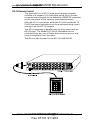
1
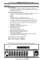
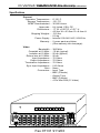
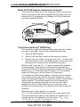
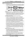
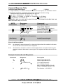
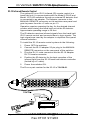
im Vertrieb von
CAMBOARD Electronics
User's Manual
MODEL 10 PLUS
MODEL 8 PLUS
SWITCHERS
www.camboard.de
Tel. 07131
[email protected]
911201
Fax 07131 911203
im Vertrieb von
CAMBOARD Electronics
www.camboard.de
Tel. 07131
[email protected]
911201
Fax 07131 911203
im Vertrieb von
CAMBOARD Electronics
Contents
Model 8/10 PLUS Introduction and Specifications ............. Chapter 1
About this Manual ................................................................. 1-1
Facts and Features ............................................................... 1-1
Description of Features ................................................. 1-2
Specifications ....................................................................... 1-3
Model 8/10 PLUS Operation and Configuration ................. Chapter 2
Operation and Front Panel Descriptions ............................... 2-1
Rear Panel Descriptions ....................................................... 2-2
Installation Guide .................................................................. 2-3
Model 10 PLUS Diagram ...................................................... 2-4
Output Select DIP Switch Setting ......................................... 2-5
Example Select DIP Switch Settings .................................... 2-6
Changing the Baud Rate ...................................................... 2-7
Model 8/10 PLUS Switcher Connection to Computer ........... 2-8
Triple Action Switching TM ...................................................... 2-8
Model 8/10 PLUS RS-232 Control ..................................... Chapter 3
RS-232 connector location and pin assignments ................. 3-1
Software ........................................................................ 3-1
Host/Switcher Communications ..................................... 3-1
Using the Command/Response Table ........................... 3-1
Command/Response Table ................................................... 3-2
Software ................................................................................ 3-3
Installing the Software ................................................... 3-3
Using the Software ........................................................ 3-3
Configuring Features and Options .................................. Appendix A
MANUAL REMOTE Connector ............................................. A-1
KP-10 Hard Wired Remote Control ...................................... A-2
IR-10 Infrared Remote Control ............................................. A-3
Rack Mounting the Model 8/10 PLUS Switchers .................. A-4
Accessories/Part Numbers ................................................... A-5
Warranty ..................................................... Inside of back cover
Safety Instructions ...................................... Inside of front cover
Written and Printed in the U.S.A.
Model 8/10 PLUS
User's Manual
68-080-01
Rev. E
79-11
www.camboard.de
Tel. 07131
[email protected]
911201
Fax 07131 911203
Page i
im Vertrieb von
CAMBOARD Electronics
Legend of Icons
The following icons may be used in this manual:
___ Important information – for example, an action or a step that
must be done before proceeding.
___ A Warning – possible damage could occur.
_ A Note, a Hint, or a Tip that may be helpful.
__ Possible Electrostatic Discharge (ESD) damage could result
from touching electronic components.
__ Additional information may be referenced in another section, or
in another document.
www.camboard.de
Tel.
07131
Extron • Model
8 PLUS
&[email protected]
Model911201
10 PLUS Switchers • User’s Manual
Fax 07131 911203
im Vertrieb von
CAMBOARD Electronics
Extron’s Model 8/10 PLUS Switchers
User’s Manual
1
Chapter One
Model 8/10 PLUS Switcher
Introduction
Features
Specifications
www.camboard.de
Tel. 07131
[email protected]
911201
Fax 07131 911203
Extron • Model 8 PLUS & Model 10 PLUS Switchers • User’s Manual
im Vertrieb von
CAMBOARD
Electronics
Model 8/10 PLUS Introduction
and Specifications
Introduction
About This Manual
This manual includes operation, configuration and option
information for the Model 8 PLUS and Model 10 PLUS (Model
8/10 PLUS) Switchers.
Model 8/10 PLUS Facts and Features
The Model 8/10 PLUS Switchers enable selection of anyone
of eight (or ten) inputs with the following formats:
•
•
•
•
RGBS
RGsB
S-Video/SVHS (Y/C) w/Stereo Audio follow
Composite Video (NTSC/PAL) w/Stereo Audio follow
The output video format of the Model 8/10 PLUS switchers
will always be the same as the selected input video format.
Standard features of the Model 8/10 PLUS switchers are:
•
•
•
•
•
•
•
•
•
•
•
Bandwidth = 300 MHz
Front Panel Control of Input Selection
Manual Remote Control Port
RS-232 Control Port
BNC Connector Inputs
Rear Panel Input LED Indicators
Unused Inputs Terminated at 75 ohms
BNC and S-Video Output Connectors
Triple Action SwitchingTM
Audio (Stereo) Follow capable with Composite or S-Video
Internal Switch Mode Power Supply
Available Models and Part Numbers are:
Model 8 PLUS Switcher – 60-094-01
Model 10 PLUS Switcher – 60-095-01
The Model 8 PLUS front and back panels are shown below.
1
Page 1-1
2
3
4
5
6
7
8
www.camboard.de
Tel.
07131
Extron • Model
8 PLUS
&[email protected]
Model911201
10 PLUS Switchers • User’s Manual
Fax 07131 911203
im Vertrieb von
CAMBOARD Electronics
Model 8/10 PLUS Introduction and Specifications
Description of Features
Outputs – Because switching is direct, the output will always have
the same format as the selected input. Separate output
connectors are provided for RGBS, S-Video, Composite
Video, and Audio.
300 MHz Bandwidth – The wide bandwidth allows signals to be
passed without loss of resolution. This is extremely important
when using high resolution computer workstations.
Triple Action SwitchingTM (RGB Delay) – Triple Action
SwitchingTM is a technique in which the RGB video is blanked
for a brief period when a new input is selected. This prevents
a distorted image from being displayed during the time the
display device sync circuitry is locking onto the new sync
input. When an input is selected, Triple-Action Switching®
does this:
1. Drop the RGB video signals leaving sync connected.
2. Wait for 20 mS and then switch to the new sync signal.
3. Wait for the time delay set by the user (0.0 - 7.5 seconds)
and then switch to the new RGB signals. (During this time
the projector is setting up to match the new sync.)
Switcher Control – Each channel of the switcher can be
controlled in any one of the following ways:
1. Front Panel Buttons.
2. Manual Remote Control Connector – KP-10 Wired
Remote Control, IR-10 Infrared Remote Control or third
party remote control.
3. RS-232 Control Connector – Provides for computer/serial
control of the switcher.
Internal Power Supply – The Model 8/10 PLUS switchers have
an internal, auto-switching (100 - 240 VAC, 50/60 Hz) power
supply. The Model 8/10 PLUS switchers are UL, CE and CSA
approved.
Rear Panel LED Indicators – Rear panel LEDs indicate which
input is selected and which outputs are active.
The Model 10 PLUS front and back panels are shown below.
1
2
3
4
5
6
7
8
9
10
www.camboard.de
Tel. 07131
[email protected]
911201
Page 1-2
Fax 07131 911203
Extron • Model 8 PLUS & Model 10 PLUS Switchers • User’s Manual
im Vertrieb von
CAMBOARD
Electronics
Model 8/10 PLUS Introduction
and Specifications
Specifications
General
Operation Temperature .... 0°-50° C
Storage Temperature .... -20°-70°
MTBF Demonstrated .... 30,000 Hours
Approvals .... UL Listed, CSA, CE
Dimensions .... 17" W x 9.25" D x 3.31" H
.... 43.2cm W x 23.5cm D x 8.4cm H
Shipping Weights .... 13.0 lbs.
.... 5.9 kg
Power Supply .... Internal 100-240 VAC, 50/60 Hz
Warranty .... 2 years parts and labor
.... (See warranty info-last page)
Video
Bandwidth .... 300 MHz
Crosstalk at 10 MHz .... -35 db (typical)
Isolation at 10 MHz .... 55 db (typical)
Return loss at 10 MHz .... 25 db
Input Impedance .... 75 Ohms
Output Impedance .... 75 Ohms
Termination Impedance .... 75 Ohms
Sync Input Impedance .... 510 Ohms
Gain .... None
Connectors .... Input Type
.... BNC (Female)
.... Output Type
.... BNC (Female)
.... 4 Pin Mini-DIN (S -Video)
1
Page 1-3
2
3
4
5
6
7
8
9
10
www.camboard.de
Tel.
07131
Extron • Model
8 PLUS
&[email protected]
Model911201
10 PLUS Switchers • User’s Manual
Fax 07131 911203
im Vertrieb von
CAMBOARD Electronics
Extron’s Model 8/10 PLUS Switchers
User’s Manual
2
Chapter Two
Model 8/10 PLUS Switcher
Operation and Installation
Switcher Operation
Front Panel
Rear Panel
Switcher Installation Guide
www.camboard.de
Tel. 07131
[email protected]
911201
Fax 07131 911203
Extron • Model 8 PLUS & Model 10 PLUS Switchers • User’s Manual
im Vertrieb von
CAMBOARD
Model 8/10 PLUSElectronics
Operation and Configuration
Model 8/10 Switcher Operation
The Model 8/10 PLUS switchers enable the output to be
switched from anyone of 8 or 10 inputs (A)* and the following
formats are supported:
•
•
•
•
•
RGBS – RGB with separate composite sync
RGsB – RGB with sync on green
Monochrome Composite Video
NTSC/PAL (Composite) Video w/Stereo Audio follow
S-Video (SVHS) w/Stereo Audio follow
When an input is selected, an LED will illuminate green next
to the selected BNC input connectors on the rear panel (H)*.
Three sets of output connectors are used for the four different
video format outputs. They are:
•
•
•
RGB (RGBS or RGsB) – 4 BNC connectors (B)*
VIDEO (NTSC/PAL) – 1 BNC connector (C)*
S-Video (SVHS) – 1 S-Video DIN connector (D)*
Audio, if used, is available on the two output BNC connectors
labeled AUDIO (L and R) (E)*.
Only one set of output connectors is active at a time. The
current active set is identified by an illuminated LED next to
the active output connector(s) (F)*.
The Output Select DIP Switch (G)* settings will determine
which of the three output connectors that the selected input
will be directed to. These switches must be set for each input
to match the incoming format. There are two switch modules,
the left switch module is for RGBS/S-Video selection and the
right switch module is for RGBS/NTSC-PAL selection. The
switch modules are numbered from top to bottom to match the
input number.
Front Panel
The POWER LED (see front panel drawing below), when
illuminated, indicates that the switcher power is on. If AC
voltage is available to the switcher, it is powered on.
Front Panel switches 1 – 10 (Model 8 = 1 – 8) shown in the
drawing below may be used to select the input. The LED in
the front panel switch for the selected input will be illuminated.
* – (A) thru (K) refer to the drawing and descriptions on the
facing page.
Model 10 PLUS Front Panel
Page 2-1
www.camboard.de
Tel.
07131
Extron • Model
8 PLUS
&[email protected]
Model911201
10 PLUS Switchers • User’s Manual
Fax 07131 911203
im Vertrieb von
CAMBOARD Electronics
Model 8/10 PLUS Operation and Configuration
Rear Panel
The following descriptions are keyed* to the Model 10 rear
panel drawing below.
A
There are four BNC connectors per input. The Model 8 PLUS
and Model 10 PLUS switchers have 8 and 10 sets of input
connectors. See "Connecting the Inputs" on page 2-3.
RGB output will be available on this set of four BNC
connectors if the selected input video format is RGB and the
S-Video/SVHS and NTSC/PAL DIP switch modules are set to
RGBS for the selected input number.
NTSC/PAL video output will be available on this BNC
connector if the selected input video format is NTSC/PAL and
the NTSC/PAL DIP switch module is set to VIDEO (S-Video/
SVHS switch is set to RGBS) for the selected input number.
S-Video output will be available on this DIN connector if the
selected input video format is S-Video and the S-Video/SVHS
DIP switch module is set to VIDEO (NTSC/PAL is set to
RGBS) for the selected input number.
Audio follow, if used, will be available on these two BNC
connectors. Audio follow is valid only with NTSC/PAL or
S-Video input video formats. The left connector is for the left
audio channel and the right connector is for the right audio
channel.
These three LEDs are located next to the three video outputs
and one of the three will illuminate to identify the connector(s)
with video output for the selected video input.
The switches within the two DIP switch modules are used to
identify the format of each video input and to steer the video to
the proper output connectors.
Selected input LEDs.
AC line voltage input connector.
RS-232 connector - See page 3-1 for a detailed description.
Remote connector - See page A-1 for a detailed description.
B
C
D
E
F
G
H
I
J
K
* – Letters next to the descriptions above are keyed to the circled
letters in the drawing below.
1
2
3
4
5
6
7
8
9
10
www.camboard.de
Tel. 07131
[email protected]
911201
Page 2-2
Fax 07131 911203
Extron • Model 8 PLUS & Model 10 PLUS Switchers • User’s Manual
im Vertrieb von
CAMBOARD
Model 8/10 PLUSElectronics
Operation and Configuration
Model 8/10 PLUS Switcher Installation Guide
The recommended installation procedure for the Model 8
PLUS and Model 10 PLUS Switchers is:
1.
Prior to installing the switcher (because it requires opening the
case) do the procedure "Changing the Baud Rate" on page 2-7
if necessary.
2. If the switcher is to be rack mounted, install it in the rack using
the procedure "Rack Mounting the Switcher" on page A-4.
3. Connect switcher input and output cables using the diagram on
the facing page as a general guide (also see "Connecting the
Inputs" below).
4. Set the Output Select DIP Switches using the procedure
"Output Select DIP Switch Setting" on page 2-5.
5. If the switcher RS-232 connector is to be used, connect it to
the computer using the procedure "Model 8/10 Switcher
Connection to Computer" on page 2-8.
6. If the Extron KP-10 Remote Control is to be used, connect it to
the switcher using the procedure on page A-2.
7. If the Extron IR-10 Remote control is to be used, connect it to
the switcher using the procedure on page A-3.
8. If a third party remote control device is to be used, connect it to
the switcher using the information on page A-1 as a guide.
9. Upon completion of switcher installation, use "Model 8/10
Switcher Operation" on page 2-1 as a guide to operate the
switcher .
10. If RS-232 control of the switcher is to be used, use Chapter 3,
"Model 8/10 PLUS RS-232 Control" as a guide.
_ If a projector is connected to the RGB output and picture
sizing, rolling, or other forms of distortion occur for an instant
after the input is switched, the Triple Action SwitchingTM
adjustment on page 2-8 may be required.
Connecting the Inputs
Use the chart below as a guide to connecting inputs to the
four BNC input connectors shown to the right. Use the inputs
listed under the appropriate video format at the top of the
table.
RGBS
R = RED
RGsB
R = RED
G = Green G = Green
Page 2-3
S-Video/SVHS
NTSC/PAL
R (Right) Audio R (Right) Audio
Y Video
Video
B = Blue
B = Blue
L (Left) Audio
L (Left) Audio
Sync
Unused
C Video
Unused
www.camboard.de
Tel.
07131
Extron • Model
8 PLUS
&[email protected]
Model911201
10 PLUS Switchers • User’s Manual
Fax 07131 911203
im Vertrieb von
CAMBOARD Electronics
SVHS VCR
1
2
3
4
5
6
7
8
9
10
Model 8/10 PLUS Operation and Configuration
_ The S-Video output from the SVHS VCR would most likely
require a user supplied S-Video to BNC adapter to connect to
the Model 8 PLUS or Model 10 PLUS switcher. The Extron
Part Number for an adapter of this type is 26-353-01.
Composite video outputs and audio outputs from Laser Disc
Players and VCRs will most likely require RCA to BNC
adapters. An adapter of this type can generally be purchased
at your local electronics store.
www.camboard.de
Tel. 07131
[email protected]
911201
Page 2-4
Fax 07131 911203
Extron • Model 8 PLUS & Model 10 PLUS Switchers • User’s Manual
im Vertrieb von
CAMBOARD
Model 8/10 PLUSElectronics
Operation and Configuration
Output Select DIP Switch Setting
As mentioned earlier, the Output Select DIP switches must be
set to define the video format of each input. The DIP Switch
modules, labeled S-VIDEO/SVHS and NTSC/PAL are shown
in the drawing at the bottom of this page. Each module has 10
(8 if Model 8 PLUS) switches which are numbered to match
the input numbers. RGBS and VIDEO labels under the switch
modules identify the left and right switch positions. When
setting the Output Select Switch Module switches, use the
following rules as a guide:
•
•
•
All RGB inputs must have the corresponding switch positions
on both switch modules set to RGBS. If all switcher inputs are
RGB format, all of the Output Select DIP switches must be set
to the RGBS position.
All S-Video inputs must have the corresponding switch
positions on the S-VIDEO/SVHS module set to VIDEO. The
corresponding NTSC/PAL switches must be in the RGBS
position.
All NTSC/PAL inputs must have the corresponding switch
positions on the NTSC/PAL switch module set to VIDEO. The
corresponding S-Video switches must be in the RGBS position.
The DIP switch modules used in the Model 8/10
PLUS switchers are the "rocker" type (see end
view drawing to the left). The major difference
between the rocker type and the "slide" type
(which could also be used) is the action
required to change the position of the switch.
To change the position of the rocker
type switch, press down on the
desired end (RGBS or VIDEO) with
a pointed object. To change the
position of the slide switch, a small
screwdriver is used to push (slide)
the switch to the desired position
(RGBS or VIDEO).
See examples on facing page.
Page 2-5
www.camboard.de
Tel.
07131
Extron • Model
8 PLUS
&[email protected]
Model911201
10 PLUS Switchers • User’s Manual
Fax 07131 911203
im Vertrieb von
CAMBOARD Electronics
Model 8/10 PLUS Operation and Configuration
Example Output Select DIP Switch Settings
The diagram below shows five inputs of a Model 8 PLUS
Switcher connected to the following devices:
1.
2.
3.
4.
5.
SVHS VCR (S-Video output to switcher)
Extron RGB 112 PLUS Interface/Workstation
Extron RGB 202xi Universal Interface/Laptop Computer
Extron RGB 202xi Universal Interface/Personal Computer
Laser Disc Player (Composite Video output to switcher)
The output select DIP switch settings for this combination of
inputs and the valid output connectors are:
Switch
#
1
2
3
4
5
Switch Module
S-Video/SVHS
VIDEO
RGBS
RGBS
RGBS
RGBS
Switch Module Video Output
NTSC/PAL
Connector
RGBS
S-VIDEO DIN
RGBS
RGBS BNCs
RGBS
RGBS BNCs
RGBS
RGBS BNCs
VIDEO
VIDEO BNC
_ Having both switch modules set to VIDEO for any switch
position (Input #) is an invalid combination.
Audio output will be available at the AUDIO output BNC
connectors when input #1 or #5 is selected.
The three video output types can be connected to a single
display that is capable of accepting all three video formats as
shown in the diagram, or, they can be split between two or
three different output devices.
1
2
3
4
5
6
7
8
www.camboard.de
Tel. 07131
[email protected]
911201
Page 2-6
Fax 07131 911203
Extron • Model 8 PLUS & Model 10 PLUS Switchers • User’s Manual
im Vertrieb von
CAMBOARD
Model 8/10 PLUSElectronics
Operation and Configuration
Changing the Baud Rate
The RS-232 protocol factory setting is 9600 baud, 8-bits, no
parity, 1 start bit and 1 stop bit. The position of internal rotary
switch SW3 on the main controller board controls the baud
rate and parity. To change the switch setting, remove the four
screws from the top of the case and lift the cover straight up.
Locate SW3 (see drawing below) and use a small, flat blade
screwdriver to rotate the switch to the desired position. SW3
switch positions are defined in the table below.
8-bit, no parity, 1 stop bit
0 = 300 baud
1 = 600 baud
2 = 1200 baud
3 = 2400 baud
4 = 4800 baud
5 = 9600 baud
6 = 19200 baud
7 = 38400 baud
8-bit, odd parity, 1 stop bit
8 = 300 baud
9 = 600 baud
A = 1200 baud
B = 2400 baud
C = 4800 baud
D = 9600 baud
E = 19200 baud
F = 38400 baud
_ Adjust SW3 to set the RS-232 Baud Rate and Protocol.
SW3 Rotary Switch
Page 2-7
www.camboard.de
Tel.
07131
Extron • Model
8 PLUS
&[email protected]
Model911201
10 PLUS Switchers • User’s Manual
Fax 07131 911203
im Vertrieb von
CAMBOARD Electronics
Model 8/10 PLUS Operation and Configuration
Model 8/10 PLUS Switcher Connection to Computer
To connect the Model 8/10 to a computer, refer to the picture
below and connect the user supplied RS-232 cable from the
computer (PC) serial port to the Model 8/10 PLUS Switcher
connector labeled RS-232.
1
2
3
4
5
6
7
8
9
10
Triple Action SwitchingTM (RGB Delay)
This prevents image scrambling during switching time. When
an input is selected, Triple Action Switching® does this:
1.
Drop the RGB signals.
2.
Wait 20 mS and then switch to the new sync signal.
3.
Wait for the time delay set by the user (0.0 - 7.5 seconds)
and then switch to the new RGB signals. (During this time
the projector is setting up to match the new sync.)
SW9 is used to set the 0.0 - 7.5 second delay (See drawing
on facing page). Each position of the switch changes the
delay by 0.5 seconds and the adjustment range is 0.0 (Switch
position 0) to 7.5 seconds (Switch position F). The switcher
ships with SW9 set to the 0 position (0.0 seconds).
To change the SW9 switch position, remove the four screws
from the top of the case and lift the cover straight up. Use a
small, flat blade screwdriver to rotate the switch to the desired
switch position. The switch position can be calculated by
measuring (estimating) the period of time that the video
appears out of sync after switching to a new input, then
multiply the time period by 2 to determine the switch position.
Example:
Measured out of sync period = 4 seconds
4 x 2 = 8 (The required switch position for 4 seconds is #8.)
The switch positions above 9 are labeled in hexadecimal, i.e.
switch position 10 is labeled A on the switch. (10Dec = AHex,
11 = B, 12 = C, 13 = D, 14 = E and 15 = F)
www.camboard.de
Tel. 07131
[email protected]
911201
Page 2-8
Fax 07131 911203
Extron • Model 8 PLUS & Model 10 PLUS Switchers • User’s Manual
im Vertrieb von
CAMBOARD Electronics
Notes:
www.camboard.de
Tel.
07131
Extron • Model
8 PLUS
&[email protected]
Model911201
10 PLUS Switchers • User’s Manual
Fax 07131 911203
im Vertrieb von
CAMBOARD Electronics
Extron’s Model 8/10 PLUS Switchers
User’s Manual
3
Chapter Three
Model 8/10 PLUS RS-232 Control
Host/Switcher Communications
Command/Response Table
Control Software
www.camboard.de
Tel. 07131
[email protected]
911201
Fax 07131 911203
Extron • Model 8 PLUS & Model 10 PLUS Switchers • User’s Manual
im Vertrieb von
CAMBOARD
Electronics
Model
8/10 PLUS RS-232 Control
Model 8/10 PLUS RS-232 Control
The Model 8/10 PLUS switchers can be controlled through the
RS-232 port by a Host device/system. The RS-232 connector
location and pin assignments are shown in the drawing below.
1
Software
Each Model 8/10 PLUS switcher ships with a 3.5" diskette
containing Extron's Windows® compatible UNIVSW Control
Software which enables the user to select the input and check
switcher status in a Windows “point and click” environment.
This software will be covered later in this chapter.
Host/Switcher Communications
The Model 8/10 PLUS Switchers treat any character that
comes in on the RS-232 port as a possible command but
accepts only a limited number as legal commands. There are
no codes required to say that a command is coming, or that a
command has ended. A simple command may be a single
character typed on a keyboard and does not require any
special characters before or after. (i.e. It is not necessary to
press “enter” from the keyboard.) Simple commands could be
from a terminal, or any other controlling device.
When the Model 8/10 PLUS switcher receives a command
and determines that it is valid, it will execute the command
and send a response back to the controlling (Host) device. If
the command is determined by the Model 8/10 PLUS switcher
to be invalid, an error response will be returned to the Host.
All responses from the switcher to the Host begin and end
with a carriage return and a line feed (CR/LF) signaling the
end of the Response character string (string = one or more
characters).
Using the Command/Response Table
The table on the following page lists those commands which
the Model 8/10 PLUS switchers recognize as valid and the
responses that will be returned to the Host. The Description
column defines the Command, the results of executing the
Command, or a definition of the response.
The Command string in the left hand column of the table is
defined in the right hand column. The Command string is
shown as ASCII characters, an ASCII to HEX conversion
table is provided.
Page 3-1
www.camboard.de
Tel.
07131
Extron • Model
8 PLUS
&[email protected]
Model911201
10 PLUS Switchers • User’s Manual
Fax 07131 911203
im Vertrieb von
CAMBOARD Electronics
Model 8/10 PLUS RS-232 Control
Command/Response Table
= CR/LF
· = space
V = Input channel, T = Video Format, M = Maximum # of inputs, Q = Software version
! = Delimiter character = Indicates end of input selection character string.
Characters also accepted as delimiters are: @ $ &
= V value = (Model 8 = 1 - 8, Model 10 = 1 - 10)
= T value = (1 = RGBS, 2 = RGsB, 3 = Composite, 4 = S-Video)
= (8 if Model 8, 10 if Model 10)
= 0.00 - 9.99
ASCII/HEX: 0/30 1/31 2/32 3/33 4/34 5/35 6/36 7/37 8/38 9/39 !/26 E/45 i/69 I/49
M/4D n/6E N/4E Q/51 T/54 V/56
Definitions and Abbreviations:
ASCII
Command
i
I
!
n
N
Response
to Host
Command
Description; etc
(Same as I Below)
V ·T ·M ·Q
V
(Same as N Below)
Nxx-xxx-xx
Information Request
( V, T, M and Q defined above)
Switch to Channel
Request for Part Number
xx-xxx-xx = Part number
Possible Error Responses
(See Below)
(See Below)
E01
E10
Invalid Channel Number
Invalid Command Input
Error Code Descriptions
E01
An attempt to select channel 0 or channels higher than the switcher's M value
of 8 or 10 will cause an E01 error response.
E10
The delimiter character must be entered within three seconds of entering the
channel number, otherwise an error type E10 response will be returned to the
Host.
Example Commands and Responses
Command
Response
Description
8!
10!
V8
V10
Select input channel 8
Select input channel 10
I
V2 T4 M8 Q1.23
V2 = Input Channel 2
T4 = S-Video Format
M8 = 8 Inputs (Model 8 PLUS)
Q1.23 = Software Version 1.23
N
N60-095-01
Part Number = 60-095-01
www.camboard.de
Tel. 07131
[email protected]
911201
Page 3-2
Fax 07131 911203
Extron • Model 8 PLUS & Model 10 PLUS Switchers • User’s Manual
im Vertrieb von
CAMBOARD
Electronics
Model
8/10 PLUS RS-232 Control
Software
The Model 8/10 PLUS Switcher control software is a program
called UNIVSW. It is Windows® 3.1, 3.11 and Windows 95
compatible and provides remote control of input selection.
Installing the Software
The program is contained on a single 3.5” diskette and will
run from the floppy drive. However, it will be more convenient
to load and run it from the hard drive. To install the software
from the 3.5” floppy disk onto the hard drive, run SETUP.EXE
from the floppy disk. The program will occupy approximately 1
MB of hard drive space.
The Windows installation will create (by default) a
C:\UNIVSW directory and will place 2 icons (UNIVSW
Program and UNIVSW Help) into a group or folder titled
“Extron Electronics”.
Using the Software
Page 3-3
1.
For information about program features, double click on the
UNIVSW Help ICON in the Extron Electronics group or folder.
[Help can be accessed from its Icon (stand-alone) or from
within the program by the Menu on the Main screen or by
pressing F1 from any point within the program.]
2.
To run the software, double click on the UNIVSW Program
ICON in the Extron Electronics group or folder.
3.
A Comm menu will be displayed on the screen. Click on the
Comm Port that is connected to the Model 8/10 Switcher
RS-232 port.
4.
The Extron UNIVersal SW Control Program window displays
input selection (see picture below).
www.camboard.de
Tel.
07131
Extron • Model
8 PLUS
&[email protected]
Model911201
10 PLUS Switchers • User’s Manual
Fax 07131 911203
im Vertrieb von
CAMBOARD Electronics
SVHS VCR
1
2
3
4
5
6
7
8
9
10
Model 8/10 PLUS RS-232 Control
Model 10 PLUS Switcher w/PC RS-232 Control
www.camboard.de
Tel. 07131
[email protected]
911201
Page 3-4
Fax 07131 911203
Extron • Model 8 PLUS & Model 10 PLUS Switchers • User’s Manual
im Vertrieb von
CAMBOARD Electronics
Notes:
www.camboard.de
Tel.
07131
Extron • Model
8 PLUS
&[email protected]
Model911201
10 PLUS Switchers • User’s Manual
Fax 07131 911203
im Vertrieb von
CAMBOARD Electronics
Extron’s Model 8/10 PLUS Switchers
User’s Manual
A
Appendix A
Configuring Features and Options
Remote Connector
KP-10 Remote Control
IR-10 Remote Control
Rack Mounting
www.camboard.de
Tel. 07131
[email protected]
911201
Fax 07131 911203
Extron • Model 8 PLUS & Model 10 PLUS Switchers • User’s Manual
im Vertrieb von
CAMBOARD
Electronics
Configuring
Features and Options
MANUAL REMOTE Connector
The MANUAL REMOTE connector provides
a way to control the Model 8/10 PLUS
switchers using Extron or third party remote
control devices.
Extron Remote Control devices which are
compatible with the Model 8/10 Switchers
are the KP-10 and IR-10 which are covered
on the following pages.
MANUAL REMOTE connector pin
assignments are shown in the table to the
right. To select a different switcher input
number through the remote connector,
momentarily short the pin for the desired
input number (#) to logic ground (pin 25).
To force the switcher to select that input #
continuously, leave the short to logic ground
in place, this will override front panel input
selection.
The Tally pins can be used for remote
indication of the switcher's selected input.
Tally #1 - #10 (pins 14 - 23) will indicate the
switcher's selected input # with a logic low
(0 volts), the Tally pins are normally at logic
high (5 volts).
The schematics shown below may be used
as a guide to design and build indicator
circuits for the Tally pins. The +5 volt source
on remote connector pin 13 is limited to
100mA, if a different voltage or a higher
current is required, an external voltage
source will be necessary.
LED Indicator Circuit
Incandescent Lamp Circuits
RECOMMENDED RELAYS
MANUFACTURER
GENERAL
Aromat
ITT/Panasonic
Omron
DS2
R-Z-5C
G5Y
EXTERNAL POWER
+5V (PIN 13)
Using an
Opto-isolator
& External Power
RESISTOR VALUE
DEPENDS ON CURRENT
REQUIREMENT OF LAMP
LOW CURRENT
TQ
A5W
G6H
+5V (PIN 13)
330 Ohm
N/C
LED
+5V (PIN 13)
TALLY PIN
Using a Relay
& External
Power
1N916
330 Ohm
TALLY PIN
Page A-1
TALLY PIN
EXTERNAL POWER
www.camboard.de
Tel.
07131
Extron • Model
8 PLUS
&[email protected]
Model911201
10 PLUS Switchers • User’s Manual
Fax 07131 911203
im Vertrieb von
CAMBOARD Electronics
Configuring Features and Options
KP-10 Remote Control
The optional EXTRON KP-10 hard wired remote controller
consists of a keypad, a 25 foot cable and a 25 pin D male
connector that connects to the MANUAL REMOTE connector
on the rear panel of the switcher (see drawing below).
With the KP-10 connected, all Model 8 PLUS and Model 10
PLUS front panel operations can be duplicated using keys 0
through 9 on the KP-10 keypad.
The KP-10 operates in parallel with the front panel and the
RS-232 port. The Model 8/10 PLUS Switchers can be
controlled from any one of these three sources and no one
source has priority over the other.
The EXTRON part number for the KP-10 is 60-111-01.
1
2
3
4
5
6
7
8
9
10
www.camboard.de
Tel. 07131
[email protected]
911201
Page A-2
Fax 07131 911203
Extron • Model 8 PLUS & Model 10 PLUS Switchers • User’s Manual
im Vertrieb von
CAMBOARD
Electronics
Configuring
Features and Options
IR-10 Infrared Remote Control
The optional EXTRON IR-10 infrared (IR) remote control is a
hand held unit. It communicates with the Model 8 PLUS and
Model 10 PLUS switchers through an external IR detector that
is connected to an adapter. The adapter connects to the
MANUAL REMOTE connector on the switcher rear panel and
gets its power from the +5 volts on pin 13.
Operation requires pressing the key for the desired channel
number while aiming the hand held unit at the IR detector.
Approximate operating range is 30 feet.
The IR detector receives infrared signals from the hand held
IR-10 remote control and converts them to logic signals. The
logic signals are used by the adapter to duplicate front panel
channel selection.
To install the IR-10 remote control system do the following:
1.
Power OFF the switcher.
2.
Connect the IR-10 adapter 25 pin plug to the MANUAL
REMOTE connector on the rear panel of the switcher.
3.
Plug the RJ-11 male connector into the IR-10 Adapter
RJ-11 female connector.
4.
Position the IR detector for the best reception of the
infrared light from the IR-10 hand held remote controller
(limited by a 6' cable).
5.
Power the switcher ON.
The EXTRON part number for the IR-10 is 70-036-01.
1
2
3
4
5
6
7
8
9
10
Model 10 PLUS Switcher
Page A-3
www.camboard.de
Tel.
07131
Extron • Model
8 PLUS
&[email protected]
Model911201
10 PLUS Switchers • User’s Manual
Fax 07131 911203
im Vertrieb von
CAMBOARD Electronics
Configuring Features and Options
Rack Mounting
The Model 8 PLUS and Model 10 PLUS switchers can be
rack-mounted using an optional 19" 2U Universal Rack Shelf,
one switcher per shelf. The Extron Part Number for the
Universal Rack Shelf is 60-032-01.
The installation procedure follows.
10-32 x 3/4
Screws
#10 Beveled
Washers
Use two screws to secure switcher to shelf
Installing the 2U Shelf in a Rack
Use the four 10-32 x 3/4 black screws and #10 black beveled
washers to mount the 2U Shelf in the Rack.
Installing the Model 8/10 PLUS Switcher on the Shelf
The 2U Universal Rack Shelf is designed to enable the Model
8 PLUS or Model 10 PLUS Switcher to set on the shelf with
the switcher's four feet extending through four holes. It is not
necessary to attach the switcher to the shelf with screws.
Upon completion of this procedure, return to the Installation
Guide in Chapter 2 and continue with the next step in the
procedure.
www.camboard.de
Tel. 07131
[email protected]
911201
Page A-4
Fax 07131 911203
Extron • Model 8 PLUS & Model 10 PLUS Switchers • User’s Manual
im Vertrieb von
CAMBOARD Electronics
Accessories/Part Numbers
Model 8 PLUS Switcher .............................................. 60-094-01
Model 10 PLUS Switcher ............................................ 60-095-01
Model 8/10 PLUS User's Manual ................................ 68-080-01
Universal Rack Shelf, 19" 2U ...................................... 60-032-01C
KP-10 Remote Control ................................................ 60-111-01
IR-10 Remote Control ................................................. 70-036-01
S-VHS-BNC Adapter ................................................... 26-353-01
BNC-4 HR Cable
BNC-4-3’HR (3 feet/0.9 meters) ................................. 26-210-01
BNC-4-6’HR (6 feet/1.8 meters) ................................. 26-210-02
BNC-4-12’HR (12 feet/3.6 meters) ............................. 26-210-03
BNC-4-25’HR (25 feet/7.5 meters) ............................. 26-210-04
BNC-4-50’HR (50 feet/15.0 meters) ........................... 26-210-05
BNC-4-75’HR (75 feet/23.0 meters) ........................... 26-210-06
BNC-4-100’HR (100 feet/30.0 meters) ....................... 26-210-07
BNC-4-150’HR (150 feet/45.0 meters) ....................... 26-210-08
BNC-4-200’HR (200 feet/60.0 meters) ....................... 26-210-09
BNC-4-250’HR (250 feet/75.0 meters) ....................... 26-210-54
BNC-4-300’HR (300 feet/90.0 meters) ....................... 26-210-53
BNC-4 Mini-HR Bulk (300’/90m up to 5000’/1500m) .. 22-073-01
Page A-5
www.camboard.de
Tel.
07131
Extron • Model
8 PLUS
&[email protected]
Model911201
10 PLUS Switchers • User’s Manual
Fax 07131 911203