1
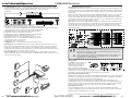
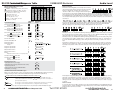
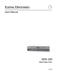
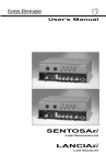
Specifications
im Vertrieb von
CAMBOARD Electronics
VGA connector pin-9 - If your equipment/application requires that the pin-9 signal of the selected input be
passed to output connector pin-9, it will be necessary to add (solder) jumpers (JMP1 = Input 1, JMP2 = Input
2, etc.) onto the inside of the rear panel (see Figure 5-A). Each jumper consists of 2 etch/solder pads
separated by approximately 1/16th inch gap. Connect (solder a wire across) the 2 pads for the desired input/
jumper (example: for Input 1, connect the JMP1 solder pads). Pin-9 pass through may be enabled for as
many inputs as desired. To access the inside of the rear panel, DISCONNECT POWER and remove four
screws from the top of the switcher. The bottom panel can then be removed. Unplug the three cables
connected to the video circuit card enabling it to be removed.
JMP3
JMP4
JMP5
JMP6
User’s Guide
JMP1
JMP2
FIGURE 5-A
Specifications
Video
Input Video Signal Level
Video Gain
Frequency Range (H. Sync)
Frequency Range (V. Sync)
RGB Video Bandwidth
Input Impedance
Output Impedance
Termination Impedance
Sync Input Impedance
Connectors - Input and Output VGA
..
..
..
..
..
..
..
..
..
..
0.5 to 2 volts p-p
Unity
15-145 kHz
30-170 Hz
350 MHz (-3 dB)
75 Ohms
75 Ohms
75 Ohms
510 Ohms
15 pin HD D-Sub (Female)
..
..
..
..
..
6 Inputs, Stereo, Balanced or Unbalanced
3.5mm Captive screw terminal, 5 conductor
19.5 dBu
25 kohms/50 kohms (DC coupled)
–15.0 dB to +9.0 dB, adjustable per input
Audio
Input
Type
Connectors
Maximum Level
Impedance Balanced/Unbalanced
Gain Adjustment
Throughput
Response .. ±.05 dB 20 Hz to 20 kHz
Maximum Channel Gain .. 15.0 dB (Input gain @ max., Balanced, Output)
Output
Type
Connector
Impedance
Gain
..
..
..
..
1 Output, Stereo, Balanced or Unbalanced
3.5mm Captive screw terminal, 5 conductor
50 Ohms unbalanced, 100 ohms balanced
Unbalanced: 0 dB, Balanced: +6 dB
General
Operation Temperature
Storage Temperature
Humidity
MTBF Demonstrated
Vibration
Approvals
Power Supply
..
..
..
..
..
..
..
..
Dimensions ..
..
Shipping Weight ..
Warranty ..
Part Numbers
SW6 VGA Audio Switcher
IR-20 Infrared Remote Control
3.5mm Captive screw connector
19" 1U Universal Rack Shelf
VGA/MAC Adapter (Composite Sync)
VGA/MAC HV Adapter (Mac H/V sync)
www.extron.com
..
..
..
..
..
..
0° to +50° C
–40° to +70° C
10% to 90% non-condensing
30,000 Hours
NSTA 1A in carton
CE, UL Listed, FCC Class A
100-240 VAC 50/60 Hz, 0.3A max.
Internal auto-switchable
1.75" H x 17.4" W x 9.5" D
4.45cm H x 44.1cm W x 24.13cm D
8 lbs. (3.6 kg)
3 years parts and labor
60-260-01
70-036-02
10-319-01
60-190-01
26-340-01
26-340-02
SW6 VGA Audio
Refer to the safety instructions
in the literature that came with
this equipment.
Extron Electronics, USA
Extron Electronics, Europe
Extron Electronics, Asia
Extron Electronics, Japan
1230 South Lewis Street
Anaheim, CA 92805
USA
714.491.1500
Fax 714.491.1517
Beeldschermweg 6C
3821 AH Amersfoort
The Netherlands
+31.33.453.4040
Fax +31.33.453.4050
135 Joo Seng Road, #04-01
PM Industrial Building
Singapore 368363
+65.6383.4400
Fax +65.6383.4664
Kyodo Building
16 Ichibancho
Chiyoda-ku, Tokyo 102-0082 Japan
+81.3.3511.7655
Fax +81.3.3511.7656
www.camboard.de
© 2006 Extron Electronics. All rights reserved.
Tel. 07131 911201
Fax 07131 911203
6-Input, 1-Output VGA — QXGA and Stereo Audio Switcher
68-377-01 Rev. D
06 06
[email protected]
Installation
and Operation
im Vertrieb
von
CAMBOARD Electronics
The SW6 VGA Audio is a 6 input - 1 output audio/video switcher housed in a rack mountable, 1U high, full
width metal enclosure with internal, universal 100-240 VAC 50/60 Hz power supply. The switcher front and
rear panels are shown in Figure 1-A followed by descriptions of controls and connectors.
F IGURE 1-A
A Power LED - ON if AC power applied. (also see item F)
B Six Input Select Buttons and LEDs - Used to select an input in Manual mode.
Hold button 1 and press and hold NORM (Normal = Manual) or AUTO (Autoswitch) button to select Mode.
Buttons 5/6 are used to increase/decrease audio setting w/Audio LED ON.
C AUDIO Button/LED - Used to set/indicate audio view/adjust operation.
D ±dB LEDs - Indicates polarity of Audio Level setting.
E IEC AC Power connector - 100-240 VAC 50/60 Hz, 0.3 amps maximum.
F Power LED - ON if AC power applied. (also see item A)
G Six VGA input connectors - Up to six VGA inputs may be connected.
H VGA output connector - Selected VGA input available at this connector.
I Six audio input captive screw connectors.
J Audio output captive screw connector.
K REMOTE connector - Used for RS-232 and/or Contact Closure control.
Using the Captive Screw Audio Connectors
The SW6 VGA Audio switcher has a single row of 3.5 mm audio receptacles along the bottom right side of the
rear panel (see items I & J, Figure 1-A) with six inputs labeled L 1 R through L 6 R, and one output. Each audio
receptacle has five contacts, and is labeled for left (L), right (R), polarity (+/–), ground, and the input numbers
plus the output.
Captive screw audio connectors (3.5 mm) are supplied (P/N 10-319-10) with the switcher, one for each input
and one for the output. Connectors must be wired to the audio cables using the captive screws inside the
connectors (FIGURE 2-B). Each audio connector will then be plugged into the appropriate input or output position
on the rear panel. Figure 2-C shows three methods of wiring the connectors, depending on your system, with
input examples across the top and output examples below.
When making connections for the SW6 VGA Audio switcher from existing audio cables, see Figure 2-A. The
round audio connectors are shown with the top one (tip and sleeve only) for unbalanced audio and the bottom
one (tip, ring and sleeve) for balanced audio. The "ring", "tip" and "sleeve" markings are also used on the
captive screw audio connector diagrams in Figure 2-C. Together, these examples may be used as a guide for
terminating audio cables.
FIGURE 2-A
Projector
PC
AUDIO
INPUTS
Extron
SW 6 VGA Audio
Switcher
Mac
Sound System
Mac
1
PC
PC
www.camboard.de
SW6 VGA
Audio • Installation and Operation
FIGURE 1-B
FIGURE 2-C
UNBALANCED INPUT
(high impedance)
TIP
SLEEVE
Tip
Sleeve
Tip (+)
Ring (-)
TIP
SLEEVE
BALANCED INPUT
BALANCED INPUT
(600 ohms)
(high impedance)
TIP
LRING
S
Gnd LEEVE(S)
Tip
RRING
L TIP 600
RING
Gnd SLEEVE(S)
R RTip
ING
Gnd
TIP
L RING
Gnd SLEEVE(S)
Tip
R R
ING
Gnd
L
R
600
Sleeve
FIGURE 2-D
L
Operating Modes - The SW6 VGA Audio switcher operates in Manual or Autoswitch Mode (see item B
above). Input selection in Manual mode may be done using Input select buttons 1 - 6 on the front panel or
through the rear panel Remote connector (contact closure or RS-232). In Autoswitch Mode the switcher
automatically selects the highest number input that has sync pulses available while blocking input selection
by the front panel switches or through the Remote connector.
Connection Diagram - The connection diagram in Figure 1-B shows four PC computers and two M AC
computers (with cable adapters) connected as inputs to the SW6 VGA Audio switcher. A projector is shown
connected to the switcher output.
PC
FIGURE 2-B
2
R
L
3
R
Tip
NO SLEEVE
SLEEVE(S)
Tip
NO SLEEVE
TIP
L RING
Gnd SLEEVE(S)
Tip
RRING
L
UNBALANCED OUTPUT
BALANCED OUTPUT
BALANCED OUTPUT
(high impedance)
(high impedance)
(600 ohms)
R
__ Do not connect equipment that uses phantom power.
__ If using Unbalanced Output example above (shaded background), connect the sleeve(s) to
Ground (Gnd). Connecting it to a negative (-) terminal will damage audio output circuits.
NO Sleeve means NO CONNECTION!
__ There is no physical way to prevent you from plugging an audio connector partially in one
input and partially in the adjacent input. Align the Audio connectors carefully before
plugging them in to avoid circuit damage.
Remote Control
The REMOTE connector enables the
switcher to be controlled from an
RS-232 Host device/system or a
contact closure device such as
Extron’s IR-20 Infrared Remote Control.
RS-232 and Contact Closure REMOTE connector pin
assignments are shown to the right. To select an input through the Remote connector contact closure pins,
momentarily1 connect the pin for the desired input number (#) to logic ground (pin 5).
Extron's Windows Compatible Software
UNIVSW is Extron's Windows® 3.1 and Windows 95 compatible program which may be used to control switcher
input selection, audio adjustments and mode selection (Manual or Autoswitch). It is supplied on a CD-ROM
from which it must be installed onto and launched from the hard drive.
To install the software onto the hard drive (it will occupy approximately 1 MB of hard disk space), run
LAUNCH.EXE from the CD. To run UNIVSW from the hard disk, double-click on the UNIVSW program icon in
the Extron Electronics group or folder. For information about program features, double-click on the UNIVSW
Help icon in the Extron Electronics group (or folder) or press the F1 key after UNIVSW is loaded.
Command/Response Table
The Command/Response table on Page 3 lists those commands which the SW6 VGA Audio switcher
recognizes as valid and the responses that will be returned to the Host. Error responses/causes and switcher
initiated messages are listed at the bottom of the table.
1
Duration of a momentary connection is defined as 100 milliseconds for the SW6 VGA Audio switcher.
Tel. 07131 911201
Fax 07131 911203
[email protected]
SW6 VGA Audio • Installation
and Operation
2
RS-232 Command/Response
Table
im Vertrieb von
RS-232 COMMAND /RESPONSE TABLE
ASCII to HEX Conversion Table
ABBREVIATIONS & D EFINITIONS:
= CR/LF, · = SPACE, A = AUDIO, AUTO = AUTOSWITCH,
C = CHANNEL-AUDIO & V IDEO, F = MODE, V = VIDEO,
M = M AXIMUM INPUTS, QVER = SOFTWARE VERSION
X1 = Ø – 6 (I NPUT Ø = MUTED OUTPUT)
X2 = SOFTWARE VERSION X.XX
X3 = NUMERICAL VALUE –15 TO +9
X4 = Ø TO 15 (16 STEPS + OR –)
X5 = M ODE - 1 = FRONT PANEL, 2 = AUTO
X6 = 6 (TOTAL # OF INPUTS)
Example: Select Input channel #2 audio
Select input channel
X1
X1
X1 &
X1
positive audio gain to
X1
attenuation to
X1 !
6!
X1 * X4 G
X4
Example: Set Input 2 Audio Gain = +7
Set channel
5&
Audio and Video
Example: Select Input channel #6 A & V
Set channel
2$
Video only
Example: Select Input channel #5 video
Select input channel
•
COMMAND
ASCII
X1 $
Command Description
Select input channel X1 Audio only
2*7G
X1 * X4 g
X4
Example: Set Input 3 Audio Gain = –13
RESPONSE
to Host
A X1
V5
C X1
C6
IN2·AUD=+7
IN X1 ·AUD= X3
IN3·AUD=–13
F1
Information request
Information request
i
I
(Same as I below)
V X1 ·A X1 ·F X5 ·QVER X2 ·M X6
V3·A3·F1·QVER1.23·M6
Request for part number
Request for part number
n
N
(Same as N below)
N6Ø-26Ø-Ø1
Query Software Version
Query Software Version
q
Q
(Same as Q below)
QVER X2
View input channel
View input channel
X1
X1
Audio Gain
Audio Gain
Example:
Explanation: Input 3 Audio Gain = –13
v X1 G
V X1 G
V3G
Error Response Codes
Invalid input channel (out of range)
Invalid input channel change (Autoswitch mode active)
Invalid mode parameter
Invalid command received by SW6 VGA Audio
Invalid value (out of range)
In Example 1 above, the AUDIO LED is blinking indicating that LEDs 1-5 represent the audio level setting for
the selected input. Input 1-5 LEDs are ON, each has a value of 3. The –dB LED is ON indicating a negative
setting. The Audio level setting for the selected input is –15 dB (5 x 3 = 15).
In Example 2 above, the AUDIO LED is blinking indicating that LEDs 1-5 represent the audio setting for the
selected input. Input 1 LED is solid ON, value = 3. Input 2 LED is blinking fast, value = 2. Total Value is 3 +
2 = 5. The +dB LED is ON indicating a positive setting. The Audio level setting is +5 dB for the selected
input.
Input buttons 5 and 6 may be used to increase or decrease the current audio level setting. To change the
setting for the last example from +5 dB to –1 dB, with the AUDIO LED still blinking, press and release the
Input 6 (decrease) button six times. Each time the button is pressed and released, the LEDs change as
follows:
IN X1 ·AUD= X3
#1
F2
Example:
Q
Explanation: Software version is 1.23 (example only)
Audio Level Control
The Audio Level Setting (Gain) for each input can be viewed,
changed and saved in memory using the switcher front panel
buttons or with RS-232 commands. The setting range is
–15 dB to +9 dB. To view or change the Audio level using the
front panel buttons, the Switcher AUDIO LED must be blinking. This is controlled by the AUDIO button. To
view or change the audio setting, first select the desired input, then press and hold the AUDIO button until
the AUDIO LED (above the AUDIO button) begins blinking. The current memory Audio Level Setting for the
selected input will be displayed in the input select LEDs (1-5). Each LED can display four possible values as
shown below.
V X1
Set Front Panel Mode
Set Auto-Switch Mode #2
I
Audio Level
The sum of the values represented by the five LEDs is the Audio Level setting for the selected input. The
+dB and/or the –dB LED will be ON to indicate the polarity of the Audio Level setting. Both LEDs ON
indicates a setting of zero (0). Examples using the LED symbols shown above follow:
A2
3*13g
Example:
CAMBOARD Electronics
QVER1.23
(Same as V below)
IN X1 ·AUD= X3
IN3·AUD=–13
EØ1
EØ6
EØ9
E1Ø
E13
SW6 VGA Audio Switcher-Initiated Messages
When a local event takes place, such as a front panel operation, the SW6 VGA Audio switcher responds by
sending a message to the Host. The switcher initiated messages are listed below (underlined).
(C) COPYRIGHT 1998, EXTRON ELECTRONICS SW6 VGA AUDIO, Vx.xx
C1
The copyright message is initiated by the switcher when it is first powered ON. Vx.xx is the
C1 identifying the current selected input = 1
software version number. This is followed by
(power-up default is input #1).
Cx
This message is sent to the Host if the input is changed using the front panel. (x = new input #)
RECONFIG
This message is sent to the Host when there is a change in the audio level setting.
The switcher does not expect a response from the Host to any of the above switcher-initiated messages.
3
SW6www.camboard.de
VGA Audio • RS-232 Command Response Table
The displayed setting in the example above has changed to –1 dB. However, the stored setting in memory
will remain at +5 dB until the new setting is saved. Press and hold the AUDIO button to save the current
displayed setting in memory. Release the AUDIO button when the AUDIO LED goes OFF. The audio level
setting can also be loaded using RS-232 commands. See “RS-232 Command/Response Table” on page 3
for details.
Audio Level Reset
To reset the audio level to 0 dB for all inputs, press and hold the AUDIO button. The AUDIO LED will begin
to blink. Continue to hold the AUDIO button in (approximately 10 seconds) until the AUDIO LED goes OFF.
All input audio levels will be set to 0 dB.
Tel. 07131 911201
Fax 07131 911203
[email protected]
SW6 VGA Audio • Audio Level
4