1
NEXCOM International Co., Ltd.
Industrial Computing Solutions
Fanless Computer
NISE 3500, NISE 3500M Series
User Manual
NEXCOM International Co., Ltd.
Published December 2011
www.nexcom.com
Contents
Contents
Preface
Rear Panel of NISE 3500/3500M..........................................................6
Mechanical Dimensions............................................................................7
NISE 3500/3500M...............................................................................7
Copyright .............................................................................................. iv
Disclaimer .............................................................................................. iv
Acknowledgements ............................................................................... iv
Regulatory Compliance Statements ........................................................ iv
Declaration of Conformity....................................................................... iv
RoHS Compliance.................................................................................... v
Warranty and RMA................................................................................. vi
Safety Information .................................................................................vii
Installation Recommendations.................................................................vii
Safety Precautions..................................................................................viii
Technical Support and Assistance............................................................ ix
Conventions Used in this Manual............................................................ ix
Global Service Contact Information.......................................................... x
Package Contents...................................................................................xii
Ordering Information.............................................................................xiii
Chapter 2: Jumpers And Connectors
Before You Begin.....................................................................................8
Precautions..............................................................................................8
Jumper Settings.......................................................................................9
Locations of the Jumpers and Connectors..............................................10
NISB 3500.........................................................................................10
Jumpers.................................................................................................12
Clear CMOS......................................................................................12
Connectors Pin Definitions.....................................................................13
External I/O Interface - Front Panel.....................................................13
USB Ports......................................................................................13
eSATA Ports..................................................................................13
IEEE1394b Connector (NISE 3500M only)......................................14
HDMI Connector (NISE 3500M only).............................................14
Status Indicators...........................................................................15
LAN1/LAN2 Link/Active LED..........................................................15
ATX Power On/Off Switch.............................................................16
External I/O Interface - Rear Panel......................................................17
Remote Power On/Off Switch.......................................................17
PS/2 Keyboard/Mouse Port............................................................17
9V-30V DC Input..........................................................................18
GPIO Connector...........................................................................18
Chapter 1: Product Introduction
Overview.................................................................................................1
NISE 3500...........................................................................................1
NISE 3500M........................................................................................2
Hardware Specifications...........................................................................3
Getting to Know NISE 3500 Series...........................................................5
Front Panel of NISE 3500.....................................................................5
Front Panel of NISE 3500M..................................................................5
Copyright © 2011 NEXCOM International Co., Ltd. All Rights Reserved.
ii
NISE 3500, NISE 3500M User Manual
Contents
Installing a Half Length SATA DOM with SATA HD (NISE
3500P2/3500M2/3500M2 E)..................................................................44
Installing a Full Length SATA DOM.........................................................46
Wallmount Brackets...............................................................................48
Serial Interface (COM 1 - COM 4).................................................19
LAN Ports.....................................................................................21
USB Ports......................................................................................22
VGA Port......................................................................................22
DVI-I Port......................................................................................23
Speaker-out Jack...........................................................................23
Mic-in Jack...................................................................................24
Internal Connectors...........................................................................25
ATX Power Output Connector.......................................................25
Reset Connector...........................................................................25
SMBus DATA/CLK Pin Header........................................................26
LVDS Backlight Power Select.........................................................26
LVDS Channel A Connector..........................................................27
LVDS Channel B Connector...........................................................27
LVDS Backlight Connector.............................................................28
SATA Ports....................................................................................29
SATA Power Connectors...............................................................29
SATA DOM Power Connectors......................................................30
USB Port Connector......................................................................30
COM4 RI Pin Header.....................................................................31
GPIO LED Connector.....................................................................31
Line-in Connector.........................................................................32
Internal Power/HDD/LAN Power/LAN Active LED...........................32
Smart Fan Connectors..................................................................33
COM5 Connector.........................................................................33
Parallel Connector........................................................................34
Chapter 4: BIOS Setup
About BIOS Setup..................................................................................49
When to Configure the BIOS..................................................................49
Default Configuration............................................................................50
Entering Setup.......................................................................................50
Legends.................................................................................................50
BIOS Setup Utility...................................................................................51
Chapter 5: AMT Settings
Enable Intel® AMT in the AMI BIOS........................................................64
Configure the Intel® ME Setup...............................................................65
Unconfigure AMT/ME............................................................................83
Appendix A: Power Consumption......................... 85
Appendix B: GPI/O Programming Guide............... 87
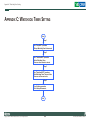
Appendix C: Watchdog Timer Setting................... 88
Appendix D: Intel Embedded AMT Management
Express KVM...................................... 90
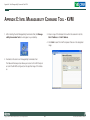
Appendix E: Intel Manageability Command Tool KVM.................................................... 97
Chapter 3: System Setup
Removing the Chassis Cover .................................................................35
Installing a DIMM...................................................................................36
Installing the CPU..................................................................................38
Installing a SATA Hard Drive...................................................................41
Copyright © 2011 NEXCOM International Co., Ltd. All Rights Reserved.
Appendix F: External Anti-vibration Kit................ 103
Appendix G: NISE3500iP2 Series with Isolated DC Input Design...................................... 107
iii
NISE 3500, NISE 3500M User Manual
Preface
Preface
Copyright
Regulatory Compliance Statements
This publication, including all photographs, illustrations and software, is
protected under international copyright laws, with all rights reserved. No
part of this manual may be reproduced, copied, translated or transmitted
in any form or by any means without the prior written consent from
NEXCOM International Co., Ltd.
This section provides the FCC compliance statement for Class B devices
and describes how to keep the system CE compliant.
Declaration of Conformity
FCC
Disclaimer
This equipment has been tested and verified to comply with the limits for
a Class B digital device, pursuant to Part 15 of FCC Rules. These limits are
designed to provide reasonable protection against harmful interference
when the equipment is operated in a commercial environment. This equipment generates, uses, and can radiate radio frequency energy and, if not
installed and used in accordance with the instructions, may cause harmful
interference to radio communications. Operation of this equipment in a
residential area (domestic environment) is likely to cause harmful interference, in which case the user will be required to correct the interference
(take adequate measures) at their own expense.
The information in this document is subject to change without prior notice
and does not represent commitment from NEXCOM International Co., Ltd.
However, users may update their knowledge of any product in use by constantly checking its manual posted on our website: http://www.nexcom.
com. NEXCOM shall not be liable for direct, indirect, special, incidental, or
consequential damages arising out of the use of any product, nor for any
infringements upon the rights of third parties, which may result from such
use. Any implied warranties of merchantability or fitness for any particular
purpose is also disclaimed.
CE
Acknowledgements
The product(s) described in this manual complies with all applicable European Union (CE) directives if it has a CE marking. For computer systems to
remain CE compliant, only CE-compliant parts may be used. Maintaining
CE compliance also requires proper cable and cabling techniques.
NISE 3500/3500M is a trademark of NEXCOM International Co., Ltd. All
other product names mentioned herein are registered trademarks of their
respective owners.
Copyright © 2011 NEXCOM International Co., Ltd. All Rights Reserved.
iv
NISE 3500, NISE 3500M User Manual
Preface
RoHS Compliance
How to recognize NEXCOM RoHS Products?
For existing products where there are non-RoHS and RoHS versions, the
suffix “(LF)” will be added to the compliant product name.
NEXCOM RoHS Environmental Policy and Status
Update
All new product models launched after January 2006 will be RoHS compliant. They will use the usual NEXCOM naming convention.
NEXCOM is a global citizen for building the digital
infrastructure. We are committed to providing green
products and services, which are compliant with European Union RoHS (Restriction on Use of Hazardous Substance in Electronic
Equipment) directive 2002/95/EU, to be your trusted green partner and to
protect our environment.
RoHS restricts the use of Lead (Pb) < 0.1% or 1,000ppm, Mercury (Hg)
< 0.1% or 1,000ppm, Cadmium (Cd) < 0.01% or 100ppm, Hexavalent
Chromium (Cr6+) < 0.1% or 1,000ppm, Polybrominated biphenyls (PBB)
< 0.1% or 1,000ppm, and Polybrominated diphenyl Ethers (PBDE) < 0.1%
or 1,000ppm.
In order to meet the RoHS compliant directives, NEXCOM has established
an engineering and manufacturing task force in to implement the introduction of green products. The task force will ensure that we follow the
standard NEXCOM development procedure and that all the new RoHS
components and new manufacturing processes maintain the highest
industry quality levels for which NEXCOM are renowned.
The model selection criteria will be based on market demand. Vendors and
suppliers will ensure that all designed components will be RoHS compliant.
Copyright © 2011 NEXCOM International Co., Ltd. All Rights Reserved.
v
NISE 3500, NISE 3500M User Manual
Preface
Warranty and RMA
NEXCOM Warranty Period
?? Any products returned by NEXCOM to other locations besides the customers’ site will bear an extra charge and will be billed to the customer.
NEXCOM manufactures products that are new or equivalent to new in
accordance with industry standard. NEXCOM warrants that products will
be free from defect in material and workmanship for 2 years, beginning
on the date of invoice by NEXCOM. HCP series products (Blade Server)
which are manufactured by NEXCOM are covered by a three year warranty
period.
Repair Service Charges for Out-of-Warranty Products
NEXCOM will charge for out-of-warranty products in two categories, one
is basic diagnostic fee and another is component (product) fee.
System Level
?? Component fee: NEXCOM will only charge for main components such
as SMD chip, BGA chip, etc. Passive components will be repaired for
free, ex: resistor, capacitor.
NEXCOM Return Merchandise Authorization (RMA)
?? Customers shall enclose the “NEXCOM RMA Service Form” with the
returned packages.
?? Items will be replaced with NEXCOM products if the original one cannot
be repaired. Ex: motherboard, power supply, etc.
?? Customers must collect all the information about the problems encountered and note anything abnormal or, print out any on-screen messages,
and describe the problems on the “NEXCOM RMA Service Form” for
the RMA number apply process.
?? Replace with 3rd party products if needed.
?? If RMA goods can not be repaired, NEXCOM will return it to the customer without any charge.
?? Customers can send back the faulty products with or without accessories (manuals, cable, etc.) and any components from the card, such as
CPU and RAM. If the components were suspected as part of the problems, please note clearly which components are included. Otherwise,
NEXCOM is not responsible for the devices/parts.
Board Level
?? Component fee: NEXCOM will only charge for main components, such
as SMD chip, BGA chip, etc. Passive components will be repaired for
free, ex: resistors, capacitors.
?? Customers are responsible for the safe packaging of defective products,
making sure it is durable enough to be resistant against further damage
and deterioration during transportation. In case of damages occurred
during transportation, the repair is treated as “Out of Warranty.”
Copyright © 2011 NEXCOM International Co., Ltd. All Rights Reserved.
?? If RMA goods can not be repaired, NEXCOM will return it to the customer without any charge.
vi
NISE 3500, NISE 3500M User Manual
Preface
Warnings
Installation Recommendations
Read and adhere to all warnings, cautions, and notices in this guide and
the documentation supplied with the chassis, power supply, and accessory
modules. If the instructions for the chassis and power supply are inconsistent with these instructions or the instructions for accessory modules,
contact the supplier to find out how you can ensure that your computer
meets safety and regulatory requirements.
Ensure you have a stable, clean working environment. Dust and dirt can
get into components and cause a malfunction. Use containers to keep
small components separated.
Adequate lighting and proper tools can prevent you from accidentally
damaging the internal components. Most of the procedures that follow
require only a few simple tools, including the following:
Cautions
Electrostatic discharge (ESD) can damage system components. Do the described procedures only at an ESD workstation. If no such station is available, you can provide some ESD protection by wearing an antistatic wrist
strap and attaching it to a metal part of the computer chassis.
•
•
•
•
Safety Information
Using your fingers can disconnect most of the connections. It is recommended that you do not use needlenose pliers to disconnect connections
as these can damage the soft metal or plastic parts of the connectors.
Before installing and using the device, note the following precautions:
▪▪ Read all instructions carefully.
▪▪ Do not place the unit on an unstable surface, cart, or stand.
▪▪ Follow all warnings and cautions in this manual.
▪▪ When replacing parts, ensure that your service technician uses parts
specified by the manufacturer.
▪▪ Avoid using the system near water, in direct sunlight, or near a heating
device.
▪▪ The load of the system unit does not solely rely for support from the
rackmounts located on the sides. Firm support from the bottom is highly
necessary in order to provide balance stability.
▪▪ The computer is provided with a battery-powered real-time clock circuit.
There is a danger of explosion if battery is incorrectly replaced. Replace
only with the same or equivalent type recommended by the manufacturer. Discard used batteries according to the manufacturer’s instructions.
Copyright © 2011 NEXCOM International Co., Ltd. All Rights Reserved.
A Philips screwdriver
A flat-tipped screwdriver
A grounding strap
An anti-static pad
vii
NISE 3500, NISE 3500M User Manual
Preface
Safety Precautions
12. If the equipment is not used for a long time, disconnect it from the
power source to avoid damage by transient overvoltage.
1.
2. Keep this User Manual for later reference.
13. Never pour any liquid into an opening. This may cause fire or electrical shock.
3. Disconnect this equipment from any AC outlet before cleaning. Use a
damp cloth. Do not use liquid or spray detergents for cleaning.
14. Never open the equipment. For safety reasons, the equipment should
be opened only by qualified service personnel.
4. For plug-in equipment, the power outlet socket must be located near
the equipment and must be easily accessible.
15. If one of the following situations arises, get the equipment checked
by service personnel:
5. Keep this equipment away from humidity.
a. The power cord or plug is damaged.
6. Put this equipment on a stable surface during installation. Dropping
it or letting it fall may cause damage.
b. Liquid has penetrated into the equipment.
c. The equipment has been exposed to moisture.
7.
d. The equipment does not work well, or you cannot get it to work
according to the user’s manual.
e. The equipment has been dropped and damaged.
8. The openings on the enclosure are for air convection to protect the
equipment from overheating. DO NOT COVER THE OPENINGS.
f. The equipment has obvious signs of breakage.
9. Make sure the voltage of the power source is correct before connecting the equipment to the power outlet.
17. The unit uses a three-wire ground cable which is equipped with a
third pin to ground the unit and prevent electric shock. Do not defeat
the purpose of this pin. If your outlet does not support this kind of
plug, contact your electrician to replace your obsolete outlet.
Read these safety instructions carefully.
Do not leave this equipment in either an unconditioned environment
or in a above 40oC storage temperature as this may damage the
equipment.
16. Do not place heavy objects on the equipment.
10. Place the power cord in a way so that people will not step on it. Do
not place anything on top of the power cord. Use a power cord that
has been approved for use with the product and that it matches the
voltage and current marked on the product’s electrical range label.
The voltage and current rating of the cord must be greater than the
voltage and current rating marked on the product.
18. CAUTION: DANGER OF EXPLOSION IF BATTERY IS INCORRECTLY
REPLACED. REPLACE ONLY WITH THE SAME OR EQUIVALENT TYPE
RECOMMENDED BY THE MANUFACTURER. DISCARD USED BATTERIES ACCORDING TO THE MANUFACTURER’S INSTRUCTIONS.
11. All cautions and warnings on the equipment should be noted.
Copyright © 2011 NEXCOM International Co., Ltd. All Rights Reserved.
19. The computer is provided with CD drives that comply with the appropriate safety standards including IEC 60825.
viii
NISE 3500, NISE 3500M User Manual
Preface
Technical Support and Assistance
Conventions Used in this Manual
Warning: Information about certain situations, which if not
observed, can cause personal injury. This will prevent injury to
yourself when performing a task.
1. For the most updated information of NEXCOM products, visit NEXCOM’s website at www.nexcom.com.
2. For technical issues that require contacting our technical support team
or sales representative, please have the following information ready
before calling:
CAUTION!
– Product name and serial number
– Detailed information of the peripheral devices
– Detailed information of the installed software (operating system,
version, application software, etc.)
– A complete description of the problem
– The exact wordings of the error messages
Caution: Information to avoid damaging components or losing
data.
Note: Provides additional information to complete a task easily.
Safety Warning: This equipment is intended for installation in a
Restricted Access Location only.
Warning!
1. Handling the unit: carry the unit with both hands and handle it with
care.
2. Maintenance: to keep the unit clean, use only approved cleaning products or clean with a dry cloth.
3. CompactFlash: Turn off the unit’s power before inserting or removing a
CompactFlash storage card.
Copyright © 2011 NEXCOM International Co., Ltd. All Rights Reserved.
ix
NISE 3500, NISE 3500M User Manual
Preface
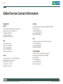
Global Service Contact Information
Headquarters
Taiwan
Germany
Leopoldstrase Business Centre, Leopoldstrase 244 80807
Munich, Germany
Tel: +49-89-208039-278
Fax: +49-89-208039-279
http://www.nexcom.eu
15F, No.920,Chung-Cheng Road, Zhonghe Dist.
New Taipei City, Taiwan 23586, R.O.C.
Tel: +886-2-8226-7786
Fax: +886-2-8226-7782
http://www.nexcom.com.tw
Italy
USA
Via Gaudenzio Ferrari 29, 21047 Saronno (VA) Italia
Tel: +39 02 9628 0333
Fax: +39 02 9619 8846
http://www.nexcom.eu
3758 Spinnaker Court,
Fremont, CA 94538, USA
Tel: +1-510-656-2248
Fax: +1-510-656-2158
http://www.nexcom.com
United Kingdom
10 Vincent Avenue, Crownhill Business Centre
Milton Keynes, Buckinghamshire, MK8 0AB
United Kingdom
Tel: +44-1908-267121
Fax: +44-1908-262042
http://www.nexcom.eu
France
Z.I. des Amandiers, 17, Rue des entrepreneurs
78420 Carrières sur Seine, France
Tel: +33 (0)1 71 51 10 20
Fax: +33 (0)1 71 51 10 21
http://www.nexcom.eu
Copyright © 2011 NEXCOM International Co., Ltd. All Rights Reserved.
x
NISE 3500, NISE 3500M User Manual
Preface
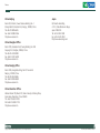
China-Beijing
Japan
Room 301, Block E, Power Creative Building, No. 1
Shangdi East Rd. Haidian Dist., Beijing, 100085, China
Tel: +86-10-5885-6655
Fax: +86-10-5885-1066
http://www.nexcom.cn
9F, Tamachi Hara Bldg.,
4-11-5, Shiba Minato-ku Tokyo,
Japan 108-0014
Tel: +81-3-5419-7830
Fax: +81-3-5419-7832
http://www.nexcom-jp.com
China-Shanghai Office
Room 1505, Greenland He Chuang Building, No. 450
Caoyang Rd. Shanghai, 200063, China
Tel: +86-21-6150-8008
Fax: +86-21-3251-6358
http://www.nexcom.cn
China-Nanjing Office
Room 1206, Hongde Building, No. 20 Yunnan Rd.
Nanjing, 210018, China
Tel: +86-25-8324-9606
Fax: +86-25-8324-9685
http://www.nexcom.cn
China-Shenzhen Office
Western Room 708, Block 210, Tairan Industry & Trading Place,
Futian Area, Shenzhen, China 518040
TEL: +86-755-833 27203
FAX: +86-755-833 27213
http://www.nexcom.cn
Copyright © 2011 NEXCOM International Co., Ltd. All Rights Reserved.
xi
NISE 3500, NISE 3500M User Manual
Preface
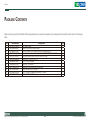
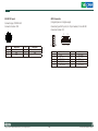
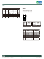
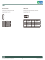
Package Contents
Before continuing, verify that the NISE 3500 Series package that you received is complete. Your package should have all the items listed in the following
table.
Item
1
2
3
4
5
6
7
8
9
10
11
12
Part Number
60233POW33X00
6023344361X00
6029900037X00
4NCPM00203X00
50311F0110X00
602DCD0269X00
7800000014X00
5060600087X00
60177A0205X00
50311P0001X00
60233MK202X00
50322P0001X00
Description
DC Power Cable
DB44 to 4x DB9 COM port cable
DOW CORNING 340 Silcone Heat Sink Compound(3g)
2 Pin Phoenix Contact: MC 1.5/2-ST-3.81(1803578), 3.81mm pitch
Flat Head Screw for HDD F3x5 ISO+NYLOK NIGP
NISB3500 CD DRIVER VER:1.0
DVI-I TO VGA Adapter
Mylar for PCI bracket
NISB3500 Quick Reference Guide VER:A
Plastic Screw for PCI card use
PS/2 Y Cable for Keyboard / Mouse, L:150mm
Plastic Nut for PCI card use
Copyright © 2011 NEXCOM International Co., Ltd. All Rights Reserved.
xii
Qty
1
1
1
1
4
1
1
1
1
1
1
1
NISE 3500, NISE 3500M User Manual
Preface
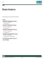
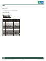
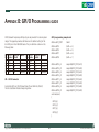
Ordering Information
The following provides ordering information for NISE 3500 Series.
• Barebone
NISE 3500M (P/N: 10J00350001X0) RoHS Compliant
-Intel® Core™ i7/i5 Fanless System
- 1 x PCI expansion slot
NISE 3500 (P/N: 10J00350000X0) RoHS Compliant
-Intel® Core™ i7/i5 Fanless System
- 1 x PCI expansion slot
NISE 3500P2 (P/N: 10J00350002X0) RoHS Compliant
-Intel® Core™ i7/i5 Fanless System
- 2 x PCI expansion slots
NISE 3500M2 E (P/N: 10J00350003X0) RoHS Compliant
-Intel® Core™ i7/i5 Fanless System
- 1 x PCI expansion slot, 1 x PCIe expansion slot
• 19V, 120W AC/DC Power Adapter w/o power cord
(P/N: 7410120002X00)
Copyright © 2011 NEXCOM International Co., Ltd. All Rights Reserved.
xiii
NISE 3500, NISE 3500M User Manual
Chapter 1: Product Introduction
Chapter 1: Product Introduction
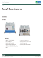
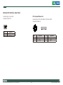
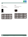
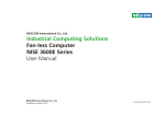
Overview
NISE 3500
Front
Rear
Key Features
• Intel® Core™ i7/i5 socket processor
• Mobile Intel® QM57 PCH
• Dual Intel® Gigabit Ethernet ports
• Dual VGA or VGA/DVI Independent Display
• 3x RS232 and 1x RS232/422/485 with Auto Flow
Control
Copyright © 2011 NEXCOM International Co., Ltd. All Rights Reserved.
• 4 x Digital Input, 4 x Digital Output
• Onboard DC to DC power design to support
9V to 30V DC power input
• Supports ATX power mode and PXE/WOL
1
NISE 3500, NISE 3500M User Manual
Chapter 1: Product Introduction
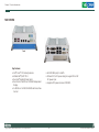
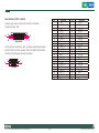
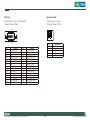
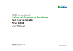
NISE 3500M
Front
Rear
Key Features
• Intel® Core™ i7/i5 socket processor
• Mobile Intel® QM57 PCH
• Dual Intel® Gigabit Ethernet ports
• Dual VGA or VGA/DVI or DVI/HDMI Independent
Display
• 3x RS232 and 1x RS232/422/485 with Auto Flow
Control
Copyright © 2011 NEXCOM International Co., Ltd. All Rights Reserved.
• 3x IEEE1394b ports, 2x eSATA
• Onboard DC to DC power design to support 9V to 30V
DC power input
• Supports ATX power mode and PXE/WOL
2
NISE 3500, NISE 3500M User Manual
Chapter 1: Product Introduction
Hardware Specifications
I/O Interface - Rear
Note: The actual memory size is dynamic. It is based on the OS I/O resource allocation.
• 2-pin Remote Power on/off switch
• 9 ~ 30V DC input
• 1 x PS/2 for Keyboard/Mouse
• 1 x DB15 male connector for GPIO (4x digital-input and 4x digital-output)
• 1 x DB44 Serial Port for 4x RS232
(COM2: RS232/422/485 with Auto Flow Control)
• 2 x Gbe LAN ports
• 4 x USB2.0 ports
• 1 x DB15 VGA port
• 1 x DVI-I Port
• 1 x Speaker-out
• 1 x Mic-in
I/O Interface - Front
Device
• ATX power on/off switch
• HDD Access / Power status LEDs
• 2 x USB2.0 ports
• 2 x eSATA ports
• 3 x IEEE1394b ports (NISE 3500M only)
• 1 x HDMI port (NISE 3500M only)
• 1 x 2.5” HDD drive bay
Main Board
• NISB 3500
• Onboard Mobile Intel® QM57 Platform Controller Hub
• Supports Intel® Core™ i7-620M PGA Processor (2.66GHz, 4M Cache)
• Supports Intel® Core™ i5-520M PGA Processor (2.4GHz, 3M Cache)
• Supports Intel® P4500 PGA Processor (1.86GHz, 2M Cache)
Main Memory
• 2x 240-pin memory DIMM, up to 4GB DDR3 800/1066MHz SDRAM,
unbuffered and non-ECC
Copyright © 2011 NEXCOM International Co., Ltd. All Rights Reserved.
Expansion
• One PCI expansion
• Max. Supported Add-on Card Length: 169mm
3
NISE 3500, NISE 3500M User Manual
Chapter 1: Product Introduction
Power Requirements
• ATX power mode
• Onboard DC to DC power support from 9V to 30V DC
• Optional power adapter
Dimensions
• 195mm (W) x 268mm (D) x 80mm (H) (7.7” x 10.5” x 3.1”)
Construction
• Aluminum chassis with fanless design
Environment
• Operating temperature:
Ambient with airflow: -5°C to 55°C
(According to IEC60068-2-1, IEC60068-2-2, IEC60068-2-14)
• Storage temperature: -20°C to 80°C
• Relative humidity: 10% to 93% (Non-Condensing)
Certifications
• CE approval
• FCC Class A
Copyright © 2011 NEXCOM International Co., Ltd. All Rights Reserved.
4
NISE 3500, NISE 3500M User Manual
Chapter 1: Product Introduction
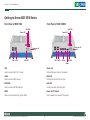
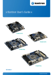
Getting to Know NISE 3500 Series
Front Panel of NISE 3500
Front Panel of NISE 3500M
LAN LEDs
LAN LEDs
Power LED
Power LED
Power on/off
switch
Power on/off
switch
USB eSATA
USB eSATA
HDD LED
1394b
HDD LED
HDMI
USB
Power LED
Used to connect USB 2.0/1.1 devices.
Indicates the power status of the system.
eSATA
HDD LED
Used to connect eSATA devices.
Indicates the status of the hard drive.
IEEE1394b
LAN LEDs
Used to connect IEEE1394b devices.
Indicate the status of the LAN ports.
HDMI
Power On/Off Switch
Used to connect devices that support HDMI.
Press to power-on or power-off the system.
Copyright © 2011 NEXCOM International Co., Ltd. All Rights Reserved.
5
NISE 3500, NISE 3500M User Manual
Chapter 1: Product Introduction
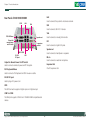
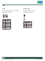
Rear Panel of NISE 3500/3500M
GPIO
LAN
LAN
Used to connect the system to a local area network.
VGA
USB
Used to connect USB 2.0/1.1 devices.
VGA
PS/2 KB/Mouse
Used to connect an analog VGA monitor.
Speaker-out
Output for
remote power
on/off swtich
DVI
1 expansion
card slot
Used to connect a digital LCD panel.
Speaker-out
COM1-COM4
9V-30V
DC Input
Used to connect a headphone or a speaker.
USB
Mic-in
Output for Remote Power On/Off Switch
Used to connect an external microphone.
Used to connect a remote to power on/off the system.
Expansion Slot
PS/2 Keyboard/Mouse
One PCI expansion slot.
Used to connect a PS/2 keyboard and PS/2 mouse via a cable.
9V-30V DC Input
Used to plug a DC power cord.
GPIO
The GPIO connector supports 4 digital input and 4 digital output.
COM1 to COM4
The DB44 port supports 3 RS232 and 1 RS232/422/485 compatible serial
devices.
Copyright © 2011 NEXCOM International Co., Ltd. All Rights Reserved.
6
NISE 3500, NISE 3500M User Manual
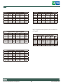
Chapter 1: Product Introduction
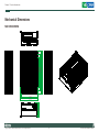
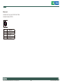
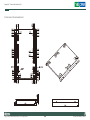
Mechanical Dimensions
184.00
224.00
264.00
268.00
NISE 3500/3500M
80.00
86.00
195.00
207.00
219.00
Copyright © 2011 NEXCOM International Co., Ltd. All Rights Reserved.
7
NISE 3500, NISE 3500M User Manual
Chapter 2: Jumpers and Connectors
tronic components. Humid environment tend to have less static electricity than dry environments. A grounding strap is warranted whenever
danger of static electricity exists.
This chapter describes how to set the jumpers on the motherboard. Note
that the following procedures are generic for all NISE 3500 series.
Before You Begin
Precautions
• Ensure you have a stable, clean working environment. Dust and dirt can
Computer components and electronic circuit boards can be damaged by
discharges of static electricity. Working on the computers that are still connected to a power supply can be extremely dangerous.
get into components and cause a malfunction. Use containers to keep
small components separated.
• Adequate lighting and proper tools can prevent you from accidentally
Follow the guidelines below to avoid damage to your computer or yourself:
damaging the internal components. Most of the procedures that follow
require only a few simple tools, including the following:
• Always disconnect the unit from the power outlet whenever you are
• A Philips screwdriver
working inside the case.
• A flat-tipped screwdriver
• If possible, wear a grounded wrist strap when you are working inside
• A set of jewelers Screwdrivers
the computer case. Alternatively, discharge any static electricity by
touching the bare metal chassis of the unit case, or the bare metal body
of any other grounded appliance.
• A grounding strap
• An anti-static pad
• Using your fingers can disconnect most of the connections. It is recom-
• Hold electronic circuit boards by the edges only. Do not touch the com-
mended that you do not use needle-nosed pliers to disconnect connections as these can damage the soft metal or plastic parts of the connectors.
ponents on the board unless it is necessary to do so. Don’t flex or stress
the circuit board.
• Leave all components inside the static-proof packaging that they
• Before working on internal components, make sure that the power
shipped with until they are ready for installation.
is off. Ground yourself before touching any internal components, by
touching a metal object. Static electricity can damage many of the elec-
Copyright © 2011 NEXCOM International Co., Ltd. All Rights Reserved.
• Use correct screws and do not over tighten screws.
8
NISE 3500, NISE 3500M User Manual
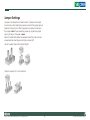
Jumper Settings
A jumper is the simplest kind of electric switch. It consists of two metal
pins and a cap. When setting the jumpers, ensure that the jumper caps are
placed on the correct pins. When the jumper cap is placed on both pins,
the jumper is short. If you remove the jumper cap, or place the jumper
cap on just one pin, the jumper is open.
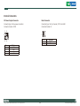
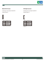
Refer to the illustrations below for examples of what the 2-pin and 3-pin
jumpers look like when they are short (on) and open (off).
Two-Pin Jumpers: Open (Left) and Short (Right)
Three-Pin Jumpers: Pins 1 and 2 Are Short
Copyright © 2011 NEXCOM International Co., Ltd. All Rights Reserved.
9
NISE 3500, NISE 3500M User Manual
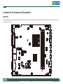
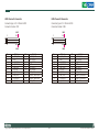
Locations of the Jumpers and Connectors
NISB 3500
The figure below is the top view of the NISB 3500 main board which is the main board used in the NISE 3500 Series system. It shows the locations of the
jumpers and connectors.
J18
J3
1
J1
CON1
SW1
J2
CN1
LED1
J4
LED2
LED3
J5
1
CN2
J6
JP1
J7
JP2
J8
CN3
J9
J10
CN4
CN5
1
J11
CN6
CN7
BAT1
CN8
CN9
JP4
CN11
Copyright © 2011 NEXCOM International Co., Ltd. All Rights Reserved.
J12
CON2
JP3
J13
DIMM1
DIMM2
CN10
J14
J15
10
NISE 3500, NISE 3500M User Manual
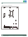
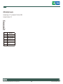
The figure below is the bottom view of the NISB 3500 main board.
J17
CN16
CN17
CN12
9
Copyright © 2011 NEXCOM International Co., Ltd. All Rights Reserved.
J16
CN15 CN13 CN14
11
NISE 3500, NISE 3500M User Manual
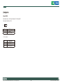
Jumpers
Clear CMOS
Connector size: 1x3 3-pin header, 2.54 mm pitch
Connector location: JP4
3
1
Pin
1-2 On
2-3 On
Settings
*Normal
CMOS Clear
1-2 On: default
Pin
1
2
3
Definition
RTCRST#_PU
RTCRST#
CLR_CMOS
Copyright © 2011 NEXCOM International Co., Ltd. All Rights Reserved.
12
NISE 3500, NISE 3500M User Manual
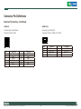
Connector Pin Definitions
External I/O Interface - Front Panel
USB Ports
eSATA Ports
Connector type: Dual USB port
Connector location: CN10
Connector type: eSATA port
Connector location: CON2A and CON2B
Pin
1
2
3
4
5
6
Definition
+5V
USB0USB0+
GND
+5V
USB1-
Pin
7
8
22
23
26
27
Copyright © 2011 NEXCOM International Co., Ltd. All Rights Reserved.
Pin
1
2
3
4
Definition
USB1+
GND
GND
GND
GND
GND
13
Definition
GND
SATA_TXP4
SATA_TXN4
GND
Pin
5
6
7
Definition
SATA_RXN4
SATA_RXP4
GND
NISE 3500, NISE 3500M User Manual
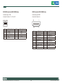
IEEE1394b Connector (NISE 3500M only)
HDMI Connector (NISE 3500M only)
Connector type:1394
Connector location: J7, J10 and J11
Connector type: HDMI
Connector location: J6
19
18
Pin
1
3
5
7
9
Description
TB2N
TA2N
1394B_SG_2
NC
GND
Pin
2
4
6
8
Copyright © 2011 NEXCOM International Co., Ltd. All Rights Reserved.
Description
TB2P
TA2P
GND
+12V
Pin
1
3
5
7
9
11
13
15
17
19
14
1
2
Definition
HDMID_D2P
HDMID_D2N
GND
HDMID_D0P
HDMID_D0N
GND
NC
HDMID_CTL_CLK
GND
HDP
Pin
2
4
6
8
10
12
14
16
18
Definition
GND
HDMID_D1P
HDMID_D1N
GND
HDMID_LKP
HDMID_LKN
NC
HDMID_CTL_SDA
+5V
NISE 3500, NISE 3500M User Manual
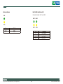
Status Indicators
LAN1/LAN2 Link/Active LED
Connector location: LED1 and LED2
PWR
LINK1
LINK2
ACT1
ACT2
HDD
Status
PWR
HDD
LED Color
Green
Yellow
Copyright © 2011 NEXCOM International Co., Ltd. All Rights Reserved.
Pin
C1
C2
A1
A2
15
Definition
LAN2_LINK_N
LAN2_ACT_N
LAN2_LINK_P
LAN2_ACT_P
NISE 3500, NISE 3500M User Manual
ATX Power On/Off Switch
Connector location: SW1
Pin
On
Off
Definition
Blue light
Red light
Pin
1
3
A1
Definition
GND
PBT_PU
PWRLED_N
Pin
2
4
C1
Copyright © 2011 NEXCOM International Co., Ltd. All Rights Reserved.
Definition
PBT_PU
GND
PWRLED_P
16
NISE 3500, NISE 3500M User Manual
External I/O Interface - Rear Panel
Connector type: 2-pin switch
Connector location: J3
PS/2 Keyboard/Mouse Port
1
6
4
Connector type: PS/2, Mini-DIN-6, JST-2.0mm-M-180
Connector location: J5
2
Pin
1
2
6
1
2 1
Definition
GND
PBT_PU
Copyright © 2011 NEXCOM International Co., Ltd. All Rights Reserved.
5
3
Pin
1
3
5
17
Definition
5VSB
KCLK
MCLK
Pin
2
4
6
Definition
KDAT
MDAT
GND
NISE 3500, NISE 3500M User Manual
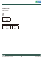
9V-30V DC Input
GPIO Connector
(4 digital input and 4 digital output)
Connector type: POWER-F-90
Connector location: CN1
Connector type:DB-15 port, 2x5 10-pin header, 2.0 mm-M-180
Connector location: JP2
2
4
1
3
Pin
1
3
5
Definition
VIN
GND
GND
Pin
2
4
Copyright © 2011 NEXCOM International Co., Ltd. All Rights Reserved.
Definition
VIN
GND
1
2
9
10
Pin
1
3
5
7
9
18
1
5
11
15
Definition
VCC5
SIO_GPI21
SIO_GPI23
SIO_GPO24
SIO_GPO26
Pin
2
4
6
8
10
Definition
SIO_GPI20
SIO_GPI22
GND
SIO_GPO25
SIO_GPO27
NISE 3500, NISE 3500M User Manual
Serial Interface (COM 1 - COM 4)
Connector type: 44-pin D-Sub, 2x22 (12.55mm x 53.04mm)
Connector location: CN4
30
1
15
44
44-pin D-Sub
16
31
The 44-pin D-Sub connector is used to connect 4 external serial devices.
Use the COM ports on the provided “DB44 to 4x DB9 COM port cable”
(included in the package) to connect the devices.
6
1
5
9
COM port
Copyright © 2011 NEXCOM International Co., Ltd. All Rights Reserved.
19
Pin
1
3
Definition
CN10_1
CN10_3
Pin
2
4
Definition
CN10_2
CN10_4
5
7
9
11
13
15
17
19
21
23
25
27
29
31
33
35
37
39
41
43
GND
CN10_7
CN10_9
CN10_11
CN10_13
GND
CN10_17
CN10_19
CN10_21
CN10_23
GND
CN10_27
CN10_29
CN10_31
CN10_33
GND
CN10_37
SP4_RI_TI
NC
NC
6
8
10
12
14
16
18
20
22
24
26
28
30
32
34
36
38
40
42
44
CN10_6
CN10_8
GND
CN10_12
CN10_14
CN10_16
CN10_18
GND
CN10_22
CN10_24
CN10_26
CN10_28
GND
CN10_32
CN10_34
CN10_36
CN10_38
GND
NC
NC
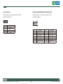
NISE 3500, NISE 3500M User Manual
COM1 (RS232) labelled “A“ on DB9 Cable Connector
DB44 Pin # DB9 Pin #
Def.
DB44 Pin # DB9 Pin #
1
1
DCD1
2
2
3
3
TXD1
4
4
5
5
GND
6
6
7
7
RTS1
8
8
9
9
RI1
10
Def.
RXD1
DTR1
DSR1
CTS1
GND
COM4 labelled “D“ on DB9 Cable Connector
DB9 Pin #
Def.
DB44 Pin # DB9 Pin #
1
DCD4
32
2
3
TXD4
34
4
5
GND
36
6
7
RTS4
38
8
9
RI4
40
Def.
RXD1
DTR1
DSR1
CTS1
GND
Note: Pin 39 is defined as an external power source, which can be selected for 5V
or 12V using JP9.
COM2 (RS232) labelled “B“ on DB9 Cable Connector
DB44 Pin # DB9 Pin #
Def.
DB44 Pin # DB9 Pin #
11
1
DCD2
12
2
13
3
TXD2
14
4
15
5
GND
16
6
17
7
RTS2
18
8
19
9
RI2
20
Def.
RXD2
DTR2
DSR2
CTS2
GND
COM3 (RS232) labelled “C“ on DB9 Cable Connector
DB44 Pin # DB9 Pin #
Def.
DB44 Pin # DB9 Pin #
21
1
DCD3
22
2
23
3
TXD3
24
4
25
5
GND
26
6
27
7
RTS3
28
8
29
9
RI3
30
Def.
RXD3
DTR3
DSR3
CTS3
GND
Copyright © 2011 NEXCOM International Co., Ltd. All Rights Reserved.
DB44 Pin #
31
33
35
37
39
COM2 (RS422) labelled “B“ on DB9 Cable Connector
DB44 Pin # DB9 Pin #
Def.
DB44 Pin # DB9 Pin #
11
1
TXD12
2
13
3
RXD+
14
4
15
5
GND
16
6
17
7
RTS#
18
8
19
9
CTS20
20
Def.
TXD+
RXDRTSCTS+
GND
NISE 3500, NISE 3500M User Manual
COM2 (RS485) labelled “B“ on DB9 Cable Connector
DB44 Pin # DB9 Pin #
Def.
DB44 Pin # DB9 Pin #
11
1
TXD12
2
RXD13
3
Reserved
14
4
15
5
Reserved
16
6
17
7
Reserved
18
8
19
9
Reserved
20
LAN Ports
Def.
TXD+
RXD+
Reserved
Reserved
Reserved
Reserved
Connector type: RJ45 port with LEDs
Connector location: CN3B and CN6B
Act
Link
Act
Orange
Blinking
Off
Pin
09
11
13
15
17
19
21
25
Copyright © 2011 NEXCOM International Co., Ltd. All Rights Reserved.
21
Status
Data Activity
No Acitivity
Definition
LAN1_M0P
LAN1_M1P
LAN1_M2N
LAN1_M3P
LAN1_LED1P
LAN1_LED2P
GND
GND
Link
Green
Always Lighted
Off
Pin
10
12
14
16
18
20
24
28
Status
Linked
No Link
Definition
LAN1_M0N
LAN1_M2P
LAN1_M1N
LAN1_M3N
LAN1_LED_ACT#
LAN1_LINK#
GND
GND
NISE 3500, NISE 3500M User Manual
USB Ports
VGA Port
Connector type: Dual USB port
Connector location: CN3A and CN6A
Connector type: DB-15 port, 15-pin D-Sub
Connector location: CN9B
Pin
1
2
3
4
5
6
Definition
+5V
USB0USB0+
GND
+5V
USB1-
Pin
7
8
22
23
26
27
Copyright © 2011 NEXCOM International Co., Ltd. All Rights Reserved.
5
1
15
11
Pin
1
4
7
10
13
MH3
Definition
USB1+
GND
GND
GND
GND
GND
22
Description
RED_VGA
DVI_GND
DVI_GND
DVI_GND
HS_VGA
DVI_GND
Pin
2
5
8
11
14
MH4
Description
GREEN_VGA
DVI_GND
DVI_GND
DVI_GND
VS_VGA
DVI_GND
Pin
3
6
9
12
15
Description
BLUE_VGA
DVI_GND
VGA_+5V
DATA_V
CLK_V
NISE 3500, NISE 3500M User Manual
DVI-I Port
Speaker-out Jack
Connector type: 29-pin D-Sub Female 90°
Connector location: CN9A
Connector type: 5-pin jack
Connector location: CN11B
1
8
17
24
Pin
01
03
05
07
09
11
13
15
17
19
21
23
C1
C3
C5A
Function
HDMI_DATA2_N
DVI_GND
NC
HDMI_CTL_SDA
HDMI_DATA1_N
DVI_GND
NC
DVI_GND
HDMI_DATA0_N
DVI_GND
DC_CLK_VGA
HDMI_LKP
DC_RED_VGA
DC_BLUE_VGA
DVI_GND
Pin
2
4
6
8
10
12
14
16
18
20
22
24
C2
C4
C5B
Pin
1
2
3
4
5
Function
HDMI_DATA2_P
NC
HDMI_CTL_CLK
DC_VSYNC_VGA
HDMI_DATA1_P
NC
HDMIC_PWR_S
HDMIC_HPDET
HDMI_DATA0_P
DC_DATA_VGA
NC
HDMI_LKN
DC_GREEN_VGA
DC_HSYNC_VGA
DVI_GND
Copyright © 2011 NEXCOM International Co., Ltd. All Rights Reserved.
23
Definition
GND
SPK_Out_R
NC
NC
SPK_Out_L
NISE 3500, NISE 3500M User Manual
Mic-in Jack
Connector size: 5-pin jack, 25.9x12.6x17.0mm
Connector location: CN11A
Pin
1
2
3
4
5
Definition
AU_GND
MIC_OUT-L
AU_GND
MIC_JD1
MIC_OUT-R
Copyright © 2011 NEXCOM International Co., Ltd. All Rights Reserved.
24
NISE 3500, NISE 3500M User Manual
Internal Connectors
DC Power Output Connector
Reset Connector
Connector type:2x2 Aux power connector
Connector location: CON1
Connector type: 1x2 2-pin header, JST 2.5mm-M-90
Connector location: J2
1
3
2
4
Pin
1
2
3
4
1
2
Pin
1
2
Definition
GND
GND
VIN
VIN
Copyright © 2011 NEXCOM International Co., Ltd. All Rights Reserved.
25
Definition
RESET#
GND
NISE 3500, NISE 3500M User Manual
SMBus DATA/CLK Pin Header
LVDS Backlight Power Select
Connector type:1x3 3-pin header 2.54mm-M-180
Connector location: J8
Connector type:1x3 3-pin header 2.54mm-M-180
Connector location: JP3
1
1
3
3
Pin
1
2
3
Definition
SMB_CLK
SMB_DATA
GND
Pin
1
2
3
Definition
VCC5
PANEL1_VDD
VCC3
*Default: 2-3
Copyright © 2011 NEXCOM International Co., Ltd. All Rights Reserved.
26
NISE 3500, NISE 3500M User Manual
LVDS Channel A Connector
LVDS Channel B Connector
Connector type: LCD-1.25mm-M-180
Connector location: CN7
Connector type: LCD-1.25mm-M-180
Connector location: CN8
MH1
MH1
1
19
1
19
2
20
2
20
MH2
MH2
Pin
1
3
5
7
9
11
13
15
Definition
L_DDC_CLK
VDD
LA_DATAP3
LA_DATAN3
GND_LVDS
LA_CLKP
LA_CLKN
GND_LVDS
Pin
2
4
6
8
10
12
14
16
Definition
L_DDC_DATA
LA_DATAP0
LA_DATAN0
VDD
LA_DATAP1
LA_DATAN1
GND_LVDS
PANEL1_BACKLIGHT
Pin
1
3
5
7
9
11
13
15
Definition
L_DDC_CLK
VDD
LB_DATAP3
LB_DATAN3
GND_LVDS
LB_CLKP
LB_CLKN
GND_LVDS
Pin
2
4
6
8
10
12
14
16
Definition
L_DDC_DATA
LB_DATAP0
LB_DATAN0
VDD
LB_DATAP1
LB_DATAN1
GND_LVDS
PANEL1_BACKLIGHT
17
19
LA_DATAP2
LA_DATAN2
18
20
PANEL1_BACKLIGHT
GND_LVDS
17
19
LB_DATAP2
LB_DATAN2
18
20
PANEL1_BACKLIGHT
GND_LVDS
Copyright © 2011 NEXCOM International Co., Ltd. All Rights Reserved.
27
NISE 3500, NISE 3500M User Manual
LVDS Backlight Connector
Connector type: 1x7 7-pin header JST-2.5mm-M-180
Connector location: J13
7
1
Pin
1
2
3
4
5
6
7
Definition
VCC5
PANEL1_BACKLIGHT
PANEL1_BACKLIGHT
L_BKLTCTL_R
GND
GND
L_BKLTEN
Copyright © 2011 NEXCOM International Co., Ltd. All Rights Reserved.
28
NISE 3500, NISE 3500M User Manual
SATA Ports
SATA Power Connectors
Connector type: Standard Serial ATAII 7P (1.27mm, SATA-M-180)
Connector location: CN12 and CN13
Connector type: 4-pin Wafer, 2.54mm-M-180
Connector location: CN14 and CN15
1
7
1
Pin
1
2
3
4
5
6
7
4
Definition
GND
SATA_TXP1
SATA_TXN1
GND
SATA_RXN1
SATA_RXP1
GND
Copyright © 2011 NEXCOM International Co., Ltd. All Rights Reserved.
Pin
1
2
3
4
29
Definition
+12V
GND
GND
VCC5
NISE 3500, NISE 3500M User Manual
SATA DOM Power Connectors
USB Port Connector
Connector type:1x2 2-pin JST wafer, 2.54mm pitch
Connector location: J16 and J17
Connector type:6-pin boxed header, JST-2.0mm-M-180
Connector location: J12
1
1
2
Pin
1
2
Definition
+12V
GND
6
Pin
1
2
3
4
5
6
Copyright © 2011 NEXCOM International Co., Ltd. All Rights Reserved.
30
Definition
+5V
USB10USB10+
USB11USB11+
GND
NISE 3500, NISE 3500M User Manual
COM4 RI Pin Header
GPIO LED Connector
Connector type:1x5 5-pin header 2.0mm -M-180
Connector location: J9
Connector type:2x2 4-pin 2.0mm -M-180
Connector location: JP1
1
3
1
Pin
1
2
3
4
5
Pin
1
2
3
4
5
2
4
Definition
VCC5
SP4_RI_T
+12V
SP4_RI_T
SP4_R
Definition
GPO_LED0
GND
GPO_LED1
GND
*Default: 4-5
Copyright © 2011 NEXCOM International Co., Ltd. All Rights Reserved.
31
NISE 3500, NISE 3500M User Manual
Line-in Connector
Internal Power/HDD/LAN Power/LAN Active LED
Connector type:1x4 4-pin header 2.5mm-M-180
Connector location: J15
Connector type:2x7 14-pin header 2.54mm-M-180
Connector location: J4
4
1
Pin
1
2
3
4
Definition
LINE1-LP
GND
LINE1-JD
LINE1-RP
Copyright © 2011 NEXCOM International Co., Ltd. All Rights Reserved.
2
14
1
13
Pin
1
3
5
7
9
11
13
32
Description
LED_PWRN
HD_LEDN
LAN1_LINK#
LAN1_LED_ACT#
LAN2_LINK#
LAN2_LED_ACT#
NC
Pin
2
4
6
8
10
12
14
Description
LED_PWRP
LED_HDDP
LAN1_LINKP
LAN1_ACTP
LAN2_LINKP
LAN2_ACTP
NC
NISE 3500, NISE 3500M User Manual
Smart Fan Connectors
COM5 Connector
Connector size: 4-pin Wafer, 2.54mm-M-180
Connector location: J1 and J14
Connector type:2x5 10-pin boxed header, 2.0mm-M-180
Connector location: CN5
4
2
1
10
9
1
Pin
1
2
3
4
Pin
1
3
5
Definition
GND
+12V
CPUFANIN_P
CPUFANOUT_R
Copyright © 2011 NEXCOM International Co., Ltd. All Rights Reserved.
7
9
33
Definition
SP5_DCD
SP5_TXD
GND
Pin
2
4
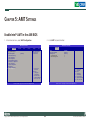
6
Definition
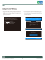
SP5_RXD
SP5_DTR
SP5_DSR
SP5_RTS
SP5_RI
8
10
SP5_CTS
GND
NISE 3500, NISE 3500M User Manual
Parallel Connector
Connector size: 2x13 26-pin box header, 2.0mm-M-180
Connector location: CN4
26
13
14
1
Pin
1
2
3
4
5
6
7
8
9
10
11
12
13
Definition
LPT_RP_STB#
LPT_RP_PRD0
LPT_RP_PRD1
LPT_RP_PRD2
LPT_RP_PRD3
LPT_RP_PRD4
LPT_RP_PRD5
LPT_RP_PRD6
LPT_RP_PRD7
LPT_ACK#R
LPT_BUSY
LPT_PE
LPT_SLCT
Pin
14
15
16
17
18
19
20
21
22
23
24
25
26
Copyright © 2011 NEXCOM International Co., Ltd. All Rights Reserved.
Definition
LPT_AFD#R
LPT_ERR#
LPT_INIT#R
LPT_SLIN#R
GND_LPT
GND_LPT
GND_LPT
GND_LPT
GND_LPT
GND_LPT
GND_LPT
GND_LPT
NC
34
NISE 3500, NISE 3500M User Manual
Chapter 3: System Setup
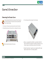
Removing the Chassis Cover
CAUTION!
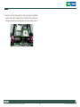
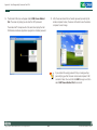
3. Lift up the cover and then remove it from the chassis.
Prior to removing the chassis cover, make sure the unit’s power is
off and disconnected from the power sources to prevent electric
shock or system damage.
1. The screws on the cover are used to secure the cover to the chassis.
2. Remove these screws and then put them in a safe place for later use.
4. Battery: one removable lithium BR2032 is pre-installed in NISE 3500
series. (CAUTION: Risk of explosion if the battery is replaced by an incorrect type. Dispose of used batteries according to the instructions.)
The dots denote the locations of the screws.
5. Optional Power adapter: Suggest to use an appropriate AC/DC power
adapter compliant with CE or UL safety regulations.
Copyright © 2011 NEXCOM International Co., Ltd. All Rights Reserved.
35
NISE 3500, NISE 3500M User Manual
Installing a DIMM
2. Note how the module is keyed to the socket. Grasping the module by
its edges, align the module with the socket so that the “notch” on the
module is aligned with the “key” on the socket. The key ensures the
module can be plugged into the socket in only one direction.
1.Push the ejector tabs which are at the ends of the socket outward. This
indicates that the socket is unlocked.
Ejector
tab
DIMM
sockets
Notch on the
module
Key on the
socket
Copyright © 2011 NEXCOM International Co., Ltd. All Rights Reserved.
36
NISE 3500, NISE 3500M User Manual
3. Seat the module vertically, pressing it down firmly until it is completely
seated in the socket. The ejector tabs at the ends of the socket will automatically snap into the locked position to hold the module in place.
Copyright © 2011 NEXCOM International Co., Ltd. All Rights Reserved.
37
NISE 3500, NISE 3500M User Manual
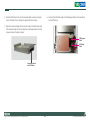
Installing the CPU
1. The CPU socket is readily accessible after you have removed the chassis
cover.
2. Make sure the screw is in its unlock position. If it’s not, use a screwdriver to turn the screw to its unlock position.
Screw in unlocked
position
CPU socket
CAUTION!
• Make sure all power cables are unplugged before you install the
CPU.
• The CPU socket must not come in contact with anything other
than the CPU. Avoid unnecessary exposure.
Copyright © 2011 NEXCOM International Co., Ltd. All Rights Reserved.
38
NISE 3500, NISE 3500M User Manual
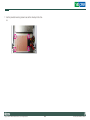
3. Position the CPU above the socket. The gold triangular mark on the
CPU must align with pin 1 of the CPU socket.
4. Insert the CPU into the socket until it is seated in place. The CPU will fit
in only one orientation and can easily be inserted without exerting any
force. Use a screwdriver to turn the screw to its lock position.
Screw in locked
position
Pin 1
Gold triangular mark
Handle the CPU by its edges and avoid touching the pins.
Copyright © 2011 NEXCOM International Co., Ltd. All Rights Reserved.
CAUTION!
39
Do not force the CPU into the socket. Forcing the CPU into the
socket may bend the pins and damage the CPU.
NISE 3500, NISE 3500M User Manual
5. Before you install the heat sink, apply thermal paste onto the top of
the CPU. Do not spread the paste all over the surface. When you later
place the heat sink on top of the CPU, the compound will disperse
evenly.
6. Align the mounting holes of the heat sink with the mounting studs on
the board and then secure the heat sink with the provided screws.
Mounting stud
Copyright © 2011 NEXCOM International Co., Ltd. All Rights Reserved.
40
NISE 3500, NISE 3500M User Manual
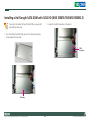
Installing a SATA Hard Drive
1. With the bottom side of the chassis facing up, remove the screws of
the bottom cover.
3. Remove the drive bay. The drive bay is used to hold a SATA hard drive.
2. Remove the 4 mounting screws that secure the drive bay to the chassis.
If you are installing one SATA drive only, the system will allow you
to install an optional CompactFlash card, a half length SATA DOM
or a full length SATA DOM.
Copyright © 2011 NEXCOM International Co., Ltd. All Rights Reserved.
41
NISE 3500, NISE 3500M User Manual
4. Place the SATA hard drive on the drive bay. Make sure the connector
side of the SATA drive is facing the opening of the drive bay.
6. Connect the SATA data cable and SATA power cable to the connectors
on the SATA drive.
5. Align the mounting holes that are on the sides of the SATA drive with
the mounting holes on the drive bay then use the provided mounting
screws to secure the drive in place.
SATA power
cable
SATA data
cable
Connector side of
the SATA drive
Copyright © 2011 NEXCOM International Co., Ltd. All Rights Reserved.
42
NISE 3500, NISE 3500M User Manual
7. Use the provided mounting screws to secure the drive bay to the chassis.
Copyright © 2011 NEXCOM International Co., Ltd. All Rights Reserved.
43
NISE 3500, NISE 3500M User Manual
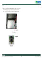
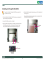
Installing a Half Length SATA DOM with SATA HD (NISE 3500P2/3500M2/3500M2 E)
If you intend to install a half length SATA DOM, you may install
one SATA hard drive only.
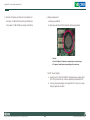
2. Locate for the SATA connector on the board.
1. Prior to installing the SATA DOM, you must first place the drive bay
shown below into the chassis.
SATA
connector
Drive bay
Copyright © 2011 NEXCOM International Co., Ltd. All Rights Reserved.
44
NISE 3500, NISE 3500M User Manual
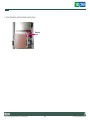
3. Align the SATA connector located on the solder side of the SATA DOM
to the SATA connector that is on the board and then press it down
firmly. Secure the SATA DOM with the provided mounting screw.
SATA DOM
Mounting screw
SATA connector
Solder side of
SATA DOM
Copyright © 2011 NEXCOM International Co., Ltd. All Rights Reserved.
45
NISE 3500, NISE 3500M User Manual
Installing a Full Length SATA DOM
If you intend to install a full length SATA DOM, you may install
one SATA hard drive only.
4. Before installing the single drive bay back, you must first replace the 4
mounting studs.
1. Prior to installing the full length SATA DOM, remove any drive bay that
may have been previously installed.
Now place the single drive bay by aligning the mounting holes of the
drive bay with the mounting studs.
2. Locate for the SATA connector on the board.
3. Align the SATA connector located on the solder side of the SATA DOM
to the SATA connector that is on the board and then press it down
firmly. Secure the SATA DOM with the provided mounting screw.
Mounting
hole
SATA DOM
Mounting screw
SATA connector
Solder side of
SATA DOM
Copyright © 2011 NEXCOM International Co., Ltd. All Rights Reserved.
46
NISE 3500, NISE 3500M User Manual
5. Secure the drive bay with the provided mounting screws.
Mounting
screw
Copyright © 2011 NEXCOM International Co., Ltd. All Rights Reserved.
47
NISE 3500, NISE 3500M User Manual
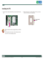
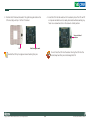
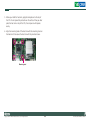
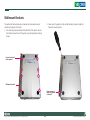
Wallmount Brackets
2. Now mount the system on the wall by fastening screws through the
bracket’s mounting holes.
The wallmount brackets provide a convenient and economical way of
mounting the system on the wall.
1. The mounting holes are located at the bottom of the system. Secure
the brackets on each side of the system using the provided mounting
screws.
Secure the bracket
to the system
Wallmount bracket
Fasten screws to
mount the system
to the wall
Copyright © 2011 NEXCOM International Co., Ltd. All Rights Reserved.
48
NISE 3500, NISE 3500M User Manual
Chapter 4: BIOS Setup
The settings made in the setup program affect how the computer performs. It is important, therefore, first to try to understand all the Setup
options, and second, to make settings appropriate for the way you use the
computer.
This chapter describes how to use the BIOS setup program for the NSA
3500 series. The BIOS screens provided in this chapter are for reference
only and may change if the BIOS is updated in the future.
To check for the latest updates and revisions, visit the NEXCOM Web site
at www.nexcom.com.tw.
When to Configure the BIOS
About BIOS Setup
This program should be executed under the following conditions:
▪▪ When changing the system configuration
The BIOS (Basic Input and Output System) Setup program is a menu driven
utility that enables you to make changes to the system configuration and
tailor your system to suit your individual work needs. It is a ROM-based
configuration utility that displays the system’s configuration status and
provides you with a tool to set system parameters.
▪▪ When a configuration error is detected by the system and you are
prompted to make changes to the Setup program
▪▪ When resetting the system clock
▪▪ When redefining the communication ports to prevent any conflicts
▪▪ When making changes to the Power Management configuration
▪▪ When changing the password or making other changes to the security
These parameters are stored in non-volatile battery-backed-up CMOS RAM
that saves this information even when the power is turned off. When the
system is turned back on, the system is configured with the values found
in CMOS.
setup
Normally, CMOS setup is needed when the system hardware is not consistent with the information contained in the CMOS RAM, whenever the
CMOS RAM has lost power, or the system features need to be changed.
With easy-to-use pull down menus, you can configure such items as:
▪▪ Hard drives, diskette drives, and peripherals
▪▪ Video display type and display options
▪▪ Password protection from unauthorized use
▪▪ Power management features
Copyright © 2011 NEXCOM International Co., Ltd. All Rights Reserved.
48
NISE 3500, NISE 3500M User Manual
Default Configuration
Legends
Most of the configuration settings are either predefined according to
the Load Optimal Defaults settings which are stored in the BIOS or are
automatically detected and configured without requiring any actions.
There are a few settings that you may need to change depending on your
system configuration.
Key
Right and Left arrows
Entering Setup
<Esc>
+ (plus key)
Up and Down arrows
When the system is powered on, the BIOS will enter the Power-On Self
Test (POST) routines. These routines perform various diagnostic checks; if
an error is encountered, the error will be reported in one of two different
ways:
▪▪ If the error occurs before the display device is initialized, a series of
beeps will be transmitted.
▪▪ If the error occurs after the display device is initialized, the screen will
display the error message.
- (minus key)
Tab
<F1>
<F10>
<Enter>
Function
Moves the highlight left or right to select a
menu.
Moves the highlight up or down between submenus or fields.
Exits to the BIOS Setup Utility.
Scrolls forward through the values or options of
the highlighted field.
Scrolls backward through the values or options
of the highlighted field.
Selects a field.
Displays General Help.
Saves and exits the Setup program.
Press <Enter> to enter the highlighted submenu.
Powering on the computer and immediately pressing <Del> allows you
to enter Setup. Another way to enter Setup is to power on the computer
and wait for the following message during the POST:
TO ENTER SETUP BEFORE BOOT
PRESS <CTRL-ALT-ESC>
Press the <Del> key to enter Setup:
Scroll Bar
When a scroll bar appears to the right of the setup screen, it indicates that
there are more available fields not shown on the screen. Use the up and
down arrow keys to scroll through all the available fields.
Submenu
When “u“ appears on the left of a particular field, it indicates that a
submenu which contains additional options are available for that field. To
display the submenu, move the highlight to that field and press <Enter>.
Copyright © 2011 NEXCOM International Co., Ltd. All Rights Reserved.
49
NISE 3500, NISE 3500M User Manual
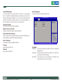
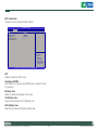
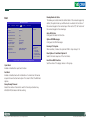
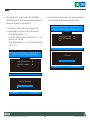
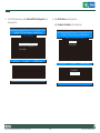
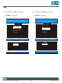
BIOS Setup Utility
Memory Information
Displays the detected system memory information.
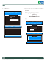
Once you enter the AMI BIOS Setup Utility, the Main Menu will appear on
the screen. The main menu allows you to select from six setup functions
and one exit choices. Use arrow keys to select among the items and press
<Enter> to accept or enter the submenu.
System Date
The date format is <day>, <month>, <date>, <year>. Day displays a day,
from Sunday to Saturday. Month displays the month, from January to December. Date displays the date, from 1 to 31. Year displays the year, from
1999 to 2099.
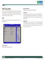
Main
The Main menu is the first screen that you will see when you enter the
BIOS Setup Utility.
Main
Advanced
BIOS SETUP UTILITY
PCIPnP
Boot
Security
BIOS Information
BIOS Vendor
Core Version
Project Version
Build Date
American Megatrends
4.6.3.7
N350-010 x64
07/28/2010 16:52:57
Memory Information
Total Memory
1024 MB (DDR3 1066)
System Date
System Time
[Wed 08/11/2010]
[16:51:35]
Access Level
Administrator
Chipset
System Time
The time format is <hour>, <minute>, <second>. The time is based on the
24-hour military-time clock. For example, 1 p.m. is 13:00:00. Hour displays
hours from 00 to 23. Minute displays minutes from 00 to 59. Second displays seconds from 00 to 59.
Exit
Use [ENTER], [TAB]
or [SHIFT-TAB] to
select a field.
Use [+] or [-] to
configure system Time.
→ ←:
↑↓: Select Screen
Select Item
Enter:Select
+/-: Change Opt.
F1: General Help
F2: Previous Values
F3: Optimized Defaults
F4: Save ESC: Exit
Version 2.00.1201. Copyright (C) 2009 American Megatrends, Inc.
BIOS Information
Displays the detected BIOS information.
Copyright © 2011 NEXCOM International Co., Ltd. All Rights Reserved.
50
NISE 3500, NISE 3500M User Manual
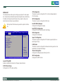
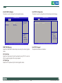
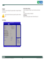
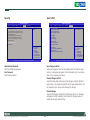
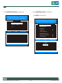
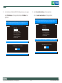
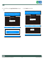
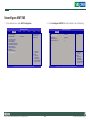
Advanced
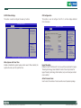
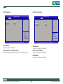
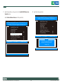
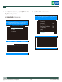
CPU Configuration
This section is used to configure the CPU. It will also display detected
CPU information.
The Advanced menu allows you to configure your system for basic operation. Some entries are defaults required by the system board, while others,
if enabled, will improve the performance of your system or let you set
some features according to your preference.
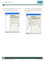
SATA Configuration
This section is used to configure the SATA drives.
Intel IGD SWSCI OpRegion
Configures the Intel graphics display.
Setting incorrect field values may cause the system to malfunction.
Main
Advanced
Legacy OpROM Support
Launch PXE OpROM
S5 RTC Wake Settings
CPU Configuration
SATA Configuration
Intel IGD SWSCI OpRegion
Intel TXT(LT) Configuration
USB Configuration
Super IO Configuration
H/W Monitor
Thermal Configuration
AMT Configuration
BIOS SETUP UTILITY
PCIPnP
Boot
Security
[Disabled]
Chipset
Intel TXT(LT) Configuration
Configures the Intel Trusted Execution technology.
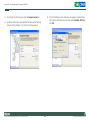
USB Configuration
Configures the USB devices.
Exit
Enable or Disable Boot
Option for Legacy
Network Devices.
Super IO Configuration
This section is used to configure the I/O functions supported by the onboard Super I/O chip.
H/W Monitor
This section is used to configure the hardware monitoring events such as
temperature, fan speed and voltages.
→ ←:
↑↓: Select Screen
Select Item
Enter:Select
+/-: Change Opt.
F1: General Help
F2: Previous Values
F3: Optimized Defaults
F4: Save ESC: Exit
Thermal Configuration
Configures the intelligent power sharing function.
AMT Configuration
Configures the AMT function.
Version 2.00.1201. Copyright (C) 2009 American Megatrends, Inc.
Launch PXE OpROM
Enables or disables the boot option for legacy network devices.
S5 RTC Wake Settings
Configures the S5 RTC wake up setting.
Copyright © 2011 NEXCOM International Co., Ltd. All Rights Reserved.
51
NISE 3500, NISE 3500M User Manual
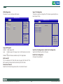
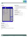
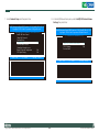
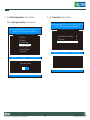
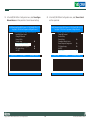
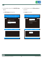
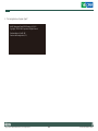
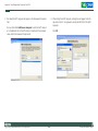
S5 RTC Wake Settings
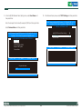
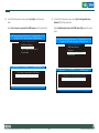
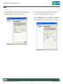
CPU Configuration
This section is used to configure the wake up function.
This section is used to configure the CPU. It will also display detected
CPU information.
BIOS SETUP UTILITY
Advanced
Wake System with Fixed Time
BIOS SETUP UTILITY
[Disabled]
Advanced
Enable or Disable
system wake on alarm
event. When enabled,
system will wake on the
hr::min::sec specified.
CPU Configuration
→ ←:
↑↓: Select Screen
Select Item
Enter:Select
+/-: Change Opt.
F1: General Help
F2: Previous Values
F3: Optimized Defaults
F4: Save ESC: Exit
Intel(R) Core(TM) i5 CPU M 540 @ 2.53GHz
EMT64
Processor Speed
Processor Stepping
Microcode Revision
Processor Cores
Intel HT Technology
Supported
2527 MHz
20652
9
2
Supported
Hyper-Threading
Active Processor Cores
Limit CPUID Maximum
Hardware Prefetcher
Adjacent Cache Line Prefetch
Intel Virtualization Technology
Power Technology
TDC Limit
TDP Limit
[Enabled]
[A11]
[Disabled]
[Enabled]
[Enabled]
[Disabled]
[Energy Efficient]
0
0
Enabled for Windows XP
and Linux (OS optimized
for Hyper-Threading
Technology) and Disabled
for other OS (OS not
optimized for
Hyper-Threading
Technology). When
Disabled only one thread
per enabled core is
enabled.
→ ←:
↑↓: Select Screen
Select Item
Enter:Select
+/-: Change Opt.
F1: General Help
F2: Previous Values
F3: Optimized Defaults
F4: Save ESC: Exit
Version 2.00.1201. Copyright (C) 2009 American Megatrends, Inc.
Version 2.00.1201. Copyright (C) 2009 American Megatrends, Inc.
Wake System with Fixed Time
Enables or disables the system’s wake on alarm event. When enabled, the
system will wake up on the specified time.
Hyper-Threading
Enable this field for Windows XP and Linux which are optimized for HyperThreading technology. Select disabled for other OSes not optimized for
Hyper-Threading technology. When disabled, only one thread per enabled
core is enabled.
Active Processor Cores
Used to enter the number of cores to enable in each processor package.
Copyright © 2011 NEXCOM International Co., Ltd. All Rights Reserved.
52
NISE 3500, NISE 3500M User Manual
SATA Configuration
This section is used to configure the SATA drives.
Limit CPUID Maximum
The CPUID instruction of some newer CPUs will return a value greater
than 3. The default is Disabled because this problem does not exist in the
Windows series operating systems. If you are using an operating system
other than Windows, this problem may occur. To avoid this problem, enable this field to limit the return value to 3 or lesser than 3.
BIOS SETUP UTILITY
Advanced
SATA Configuration
Hardware Prefetcher
Turns on or off the MLC streamer prefetcher.
Adjacent Cache Line Prefetch
Enables or disables the adjacent cache line prefetch.
Intel Virtualization Technology
When this field is set to Enabled, the VMM can utilize the additional hardware capabilities provided by Vanderpool Technology.
Not
Not
Not
Not
Present
Present
Present
Present
SATA Mode
[IDE Mode]
(1) IDE Mode.
(2) AHCI Mode.
(3) RAID Mode.
→ ←: Select Screen
↑↓: Select Item
Enter: Select
+/-: Change Opt.
F1: General Help
F2: Previous Values
F3: Optimized Defaults
F4: Save ESC: Exit
Power Technology
Configures the power management features.
Version 2.00.1201. Copyright (C) 2009 American Megatrends, Inc.
TDC Limit
Used to select the TDC limit.
SATA Mode
IDE Mode This option configures the Serial ATA drives as Parallel ATA
storage devices.
AHCI Mode This option allows the Serial ATA devices to use AHCI (Advanced Host Controller Interface).
RAID Mode This option allows you to create RAID or Intel Matrix Storage configuration on Serial ATA devices.
TDP Limit
Used to select the TDP limit.
Copyright © 2011 NEXCOM International Co., Ltd. All Rights Reserved.
SATA Port 1
SATA Port 2
SATA Port 3
SATA Port 4
53
NISE 3500, NISE 3500M User Manual
Intel TXT(LT) Configuration
This section is used to configure the Intel Trusted Execution technology.
Intel IGD SWSCI OpRegion
This section is used to configure the Intel graphics display.
BIOS SETUP UTILITY
BIOS SETUP UTILITY
Advanced
Advanced
Intel IGD SWSCI OpRegion Configuration
DVMT/FIXED Memory
IGD - Boot Type
LCD Panel Type
[256MB]
[CRT + DVI]
[VBIOS Default]
Intel Trusted Execution Technology Configuration
Select DVMT/FIXED
Mode Memory size used
by Internal Graphics
Device
→ ←: Select
↑↓: Select
Intel TXT(LT) Support
[Disabled]
→ ←: Select Screen
↑↓: Select Item
Enter: Select
+/-: Change Opt.
F1: General Help
F2: Previous Values
F3: Optimized Defaults
F4: Save ESC: Exit
Screen
Item
Enter: Select
+/-: Change Opt.
F1: General Help
F2: Previous Values
F3: Optimized Defaults
F4: Save ESC: Exit
Version 2.00.1201. Copyright (C) 2009 American Megatrends, Inc.
Version 2.00.1201. Copyright (C) 2009 American Megatrends, Inc.
DVMT/FIXED Memory
Selects the DVMT/FIXED mode memory size used by the internal graphics
device.
Intel TXT(LT) Support
The options are Enabled and Disabled.
IGD - Boot Type
Selects the video device that will be activated during POST. This will not
affect any external graphics that may be present.
LCD Panel Type
Selects the LCD panel used by the internal graphics device.
Copyright © 2011 NEXCOM International Co., Ltd. All Rights Reserved.
54
NISE 3500, NISE 3500M User Manual
USB Configuration
This section is used to configure USB devices.
Super IO Configuration
This section is used to configure the I/O functions supported by the onboard Super I/O chip.
BIOS SETUP UTILITY
Advanced
BIOS SETUP UTILITY
USB Configuration
USB Devices:
1 Mouse, 1 Hub
Legacy USB Support
EHCI Hand-off
Device Reset Timeout
[Enabled]
[Enabled
[20 Sec]
Advanced
Enables Legacy USB
support. AUTO option
disables legacy support if
no USB devices are
connected. DISABLE
option will keep USB
devices available only for
EFI applications.
Super IO Configuration
Super IO Chip
Serial Port 0 Configuration
Serial Port 1 Configuration
Serial Port 2 Configuration
Serial Port 3 Configuration
Serial Port 4 Configuration
Parallel Port Configuration
→ ←: Select Screen
↑↓: Select Item
Enter: Select
+/-: Change Opt.
F1: General Help
F2: Previous Values
F3: Optimized Defaults
F4: Save ESC: Exit
ITE IT8783F
Set Parameters of Serial
Port 1 (COMA)
→ ←: Select Screen
↑↓: Select Item
Enter: Select
+/-: Change Opt.
F1: General Help
F2: Previous Values
F3: Optimized Defaults
F4: Save ESC: Exit
Version 2.00.1201. Copyright (C) 2009 American Megatrends, Inc.
Version 2.00.1201. Copyright (C) 2009 American Megatrends, Inc.
Legacy USB Support
Enabled Enables legacy USB.
Auto Disables support for legacy when no USB devices are connected.
Disabled Keeps USB devices available only for EFI applications.
Serial Port 0 Configuration to Serial Port 4 Configuration
Selects the IO/IRQ setting of the I/O devices.
Parallel Port Configuration
Configures the parallel port.
EHCI Hand-off
This is a workaround for OSes that does not support EHCI hand-off. The
EHCI ownership change should be claimed by the EHCI driver.
Device Reset Timeout
Selects the USB mass storage device start unit command timeout.
Copyright © 2011 NEXCOM International Co., Ltd. All Rights Reserved.
55
NISE 3500, NISE 3500M User Manual
H/W Monitor
This section is used to configure the hardware monitoring events such as
temperature, fan speed and voltages.
Thermal Configuration
This section is used to configure the intelligent power sharing function.
BIOS SETUP UTILITY
Advanced
BIOS SETUP UTILITY
Intelligent Power Sharing
Advanced
[Disabled]
PC Health Status
Fan Setting
System Temperature
CPU Temperature
System FAN Speed
CPU FAN Speed
CPU:Vcore
+3.3V
+5V
+12V
[Always Full Speed]
: +30 C
: +28 C
: N/A
: N/A
: +1.056V
: +3.296 V
: +4.915V
: +11.932 V
→ ←: Select
↑↓: Select
Intelligent power sharing
configuration menu. Note:
DTS must be enabled for
Power Sharing to function.
→ ←: Select Screen
↑↓: Select Item
Enter: Select
+/-: Change Opt.
F1: General Help
F2: Previous Values
F3: Optimized Defaults
F4: Save ESC: Exit
Screen
Item
Enter: Select
+/-: Change Opt.
F1: General Help
F2: Previous Values
F3: Optimized Defaults
F4: Save ESC: Exit
Version 2.00.1201. Copyright (C) 2009 American Megatrends, Inc.
Version 2.00.1201. Copyright (C) 2009 American Megatrends, Inc.
Intelligent Power Sharing
Enables or disables the power sharing function.
Fan Setting
Selects the speed of the fan.
System Temperature and CPU Temperature
Detects and displays the internal temperature of the system and the current temperature of the CPU.
System Fan Speed to CPU Fan Speed
Detects and displays the current system fan and CPU fan speed in RPM
(Revolutions Per Minute).
CPU:Vcore to +12V
Detects and displays the output voltages.
Copyright © 2011 NEXCOM International Co., Ltd. All Rights Reserved.
56
NISE 3500, NISE 3500M User Manual
AMT Configuration
This section is used to configure the AMT function.
BIOS SETUP UTILITY
Advanced
AMT
Unconfigure AMT/ME
Watchdog Timer
OS Watchdog Timer
BIOS Watchdog Timer
[Enabled]
[Disabled]
[Disabled]
0
0
AMT Help
→ ←: Select Screen
↑↓: Select Item
Enter: Select
+/-: Change Opt.
F1: General Help
F2: Previous Values
F3: Optimized Defaults
F4: Save ESC: Exit
Version 2.00.1201. Copyright (C) 2009 American Megatrends, Inc.
AMT
Enables or disables the AMT function.
Unconfigure AMT/ME
Select Enabled to unconfigure the AMT/ME function without the need
for a password.
Watchdog Timer
Enables or disables the Watchdog Timer function.
OS Watchdog Timer
Selects the time interval of the OS Watchdog Timer.
BIOS Watchdog Timer
Selects the time interval of the BIOS Watchdog Timer.
Copyright © 2011 NEXCOM International Co., Ltd. All Rights Reserved.
57
NISE 3500, NISE 3500M User Manual
Chipset
Initiate Graphic Adapter
Selects the graphics controller to use as the primary boot device.
This section is used to configure the system based on the specific features
of the chipset.
VT-d
The options are Enabled and Disabled.
Setting incorrect field values may cause the system to malfunction.
IGD Memory
Selects the internal graphics device’s shared memory size.
North Bridge
BIOS SETUP UTILITY
Chipset
CPU Type
Arrandale
Total Memory
1024 MB (DDR3 1066)
Memory Slot 0
Memory Slot 1
1024 MB (DDR3 1066)
0 MB (DDR3 1066)
CAS# Latency (tCL)
RAS# Active Time (tRAS)
Row Precharge Time (tRP)
RAS# to CAS# Delay (tRCD)
Write Recovery Time (tWR)
Row Refresh Cycle Time (tRFC)
Write to Read Delay (tWTR)
Active to Active Delay (tRRD)
Read CAS# Precharge (tRTP)
7
20
7
7
8
60
4
4
5
Initiate Graphic Adapter
[PEG/IGD]
VT-d
[Disabled]
IGD Memory
[32M]
→ ←: Select Screen
↑↓: Select Item
Enter: Select
+/-: Change Opt.
F1: General Help
F2: Previous Values
F3: Optimized Defaults
F4: Save ESC: Exit
Version 2.00.1201. Copyright (C) 2009 American Megatrends, Inc.
Copyright © 2011 NEXCOM International Co., Ltd. All Rights Reserved.
58
NISE 3500, NISE 3500M User Manual
South Bridge
Restore AC Power Loss
Off When power returns after an AC power failure, the system’s power is
off. You must press the Power button to power-on the system.
On When power returns after an AC power failure, the system will automatically power-on.
BIOS SETUP UTILITY
Chipset
SB Chipset Configuration
SMBus Controller
GbE Controller
Wake On Lan From S5
[Enable]
[Enable]
[Enable]
Restore AC Power Loss
[Power On]
Audio Configuration
Azalia HD Audio
Azalia Internal HDMI Codec
[Enabled]
[Enabled]
Azalia HD Audio
Enables or disables the Azalia HD audio.
Azalia Internal HDMI Codec
Enables or disables the Azalia internal HDMI codec.
High Precision Event Timer Configuration
High Precision Timer
[Enabled]
USB
High Precision Timer
Enables or disables the high precision event timer.
Configuration
→ ←: Select Screen
↑↓: Select Item
Enter: Select
+/-: Change Opt.
F1: General Help
F2: Previous Values
F3: Optimized Defaults
F4: Save ESC: Exit
Version 2.00.1201. Copyright (C) 2009 American Megatrends, Inc.
SMBus Controller
Enables or disables the SMBus controller.
GbE Controller
Enables or disables the Gigabit LAN controller.
Wake On Lan From S5
When enabled, it allows the system to wake up from S5 via the network
LAN.
Copyright © 2011 NEXCOM International Co., Ltd. All Rights Reserved.
59
NISE 3500, NISE 3500M User Manual
Intel ME Configuration
USB Configuration
BIOS SETUP UTILITY
BIOS SETUP UTILITY
Advanced
Chipset
USB Configuration
All USB Devices
[Enabled]
EHCI Controller 1
EHCI Controller 2
[Disabled]
[Enabled]
Enable/Disable All USB
Devices
ME Subsystem Help
Intel ME Subsystem Configuration
ME Version
6.0.3.1195
ME Subsystem
End of Post Message
Execute MEBx
[Enabled]
[Enabled]
[Enabled]
→ ←: Select Screen
↑↓: Select Item
Enter: Select
+/-: Change Opt.
F1: General Help
F2: Previous Values
F3: Optimized Defaults
F4: Save ESC: Exit
→ ←: Select Screen
↑↓: Select Item
Enter: Select
+/-: Change Opt.
F1: General Help
F2: Previous Values
F3: Optimized Defaults
F4: Save ESC: Exit
Version 2.00.1201. Copyright (C) 2009 American Megatrends, Inc.
Version 2.00.1201. Copyright (C) 2009 American Megatrends, Inc.
All USB Devices
Enables or disables all USB devices.
ME Subsystem
The options are Enabled and Disabled.
EHCI Controller 1 and EHCI Controller 2
Enables or disables the Enhanced Host Controller Interface (USB 2.0).
End of the POST Message
The options are Enabled and Disabled.
Execute MEBx
The options are Enabled and Disabled.
Copyright © 2011 NEXCOM International Co., Ltd. All Rights Reserved.
60
NISE 3500, NISE 3500M User Manual
Boot
Bootup NumLock State
This allows you to determine the default state of the numeric keypad. By
default, the system boots up with NumLock on wherein the function of
the numeric keypad is the number keys. When set to Off, the function of
the numeric keypad is the arrow keys.
BIOS SETUP UTILITY
Main
Advanced
Chipset
Boot
Security
Save & Exit
Boot Configuration
Quiet Boot
Fast Boot
Setup Prompt Timeout
[Disabled]
[Disabled]
1
Bootup NumLock State
[On]
CSM16 Module Version
07.60
GateA20 Active
Option ROM Messages
Interrupt 19 Capture
[Upon Request]
[Force BIOS]
[Disabled]
Boot Option Priorities
Boot Option #1
Boot Option #2
[SATA: FUJITSU MH...]
[Built-in EFI Shell]
Hard Drive BBS Priorities
Enables/Disables Quiet
Boot option
Gate A20 Active
Configures the Gate A20 function.
Option ROM Messages
Configures the ROM messages.
Interrupt 19 Capture
When enabled, it allows the optional ROM to trap interrupt 19.
← →: Select Screen
↑↓: Select Item
Enter: Select
+/-: Change Opt.
F1: General Help
F2: Previous Values
F3: Optimized Defaults
F4: Save ESC: Exit
Boot Option #1 and Boot Option #2
Selects the boot sequence of the hard drives.
Version 2.00.1201. Copyright (C) 2009 American Megatrends, Inc.
Hard Drive BBS Priorities
Sets the order of the legacy devices in this group.
Quiet Boot
Enables or disables the quiet boot function.
Fast Boot
Enables or disables boot with initialization of a minimal set of devices
required to launch active boot option. This doesn’t affect the BBS boot
options.
Setup Prompt Timeout
Selects the number of seconds to wait for the setup activation key.
65535(0xFFFF) denotes indefinite waiting.
Copyright © 2011 NEXCOM International Co., Ltd. All Rights Reserved.
61
NISE 3500, NISE 3500M User Manual
Security
Save & Exit
BIOS SETUP UTILITY
BIOS SETUP UTILITY
Main
Advanced
Chipset
Boot
Security
Main
Save & Exit
Password Description
If only the Administrator’s password is set, then
this only limits access to Setup and is only asked
for when entering Setup.
If only the User’s password is set, then this is
a power on password and must be entered to
boot or enter setup. In Setup the User will have
Administrator rights.
Advanced
Chipset
Boot
Save Changes and Exit
Discard Changes and Exit
Save Changes and Reset
Discard Changes and Reset
Set Setup Administrator
Password.
Security
Save & Exit
Reset the system after
saving the changes.
Save Options
Save Changes
Discard Changes
Restore Defaults
Save as User Defaults
Restore User Defaults
Administrator Password
User Password
→ ←: Select
↑↓: Select
Screen
Item
Boot Override
SATA: FUJITSU MHZ2080BH G2
Built-in EFI Shell
Reset System with ME Disable Mode
Enter: Select
+/-: Change Opt.
F1: General Help
F2: Previous Values
F3: Optimized Defaults
F4: Save ESC: Exit
← →: Select Screen
↑↓: Select Item
Enter: Select
+/-: Change Opt.
F1: General Help
F2: Previous Values
F3: Optimized Defaults
F4: Save ESC: Exit
Version 2.00.1201. Copyright (C) 2009 American Megatrends, Inc.
Version 2.00.1201. Copyright (C) 2009 American Megatrends, Inc.
Administrator Password
Sets the administrator password.
Save Changes and Exit
To save the changes and exit the Setup utility, select this field then press
<Enter>. A dialog box will appear. Confirm by selecting Yes. You can also
press <F10> to save and exit Setup.
User Password
Sets the user password.
Discard Changes and Exit
To exit the Setup utility without saving the changes, select this field then
press <Enter>. You may be prompted to confirm again before exiting. You
can also press <ESC> to exit without saving the changes.
Discard Changes
To discard the changes, select this field then press <Enter>. A dialog box
will appear. Confirm by selecting Yes to discard all changes made and
restore the previously saved settings.
Copyright © 2011 NEXCOM International Co., Ltd. All Rights Reserved.
62
NISE 3500, NISE 3500M User Manual
Chapter 5: AMT Settings
Enable Intel® AMT in the AMI BIOS
1. In the Advanced menu, select AMT Configuration.
Main
Advanced
Legacy OpROM Support
Launch PXE OpROM
S5 RTC Wake Settings
CPU Configuration
SATA Configuration
Intel IGD SWSCI OpRegion
Intel TXT(LT) Configuration
USB Configuration
Super IO Configuration
H/W Monitor
Thermal Configuration
AMT Configuration
BIOS SETUP UTILITY
PCIPnP
Boot
Security
[Disabled]
2. In the AMT field, select Enabled.
BIOS SETUP UTILITY
Chipset
Advanced
Exit
AMT
Unconfigure AMT/ME
Watchdog Timer
OS Watchdog Timer
BIOS Watchdog Timer
Enable or Disable Boot
Option for Legacy
Network Devices.
→ ←:
↑↓: Select Screen
Select Item
Enter:Select
+/-: Change Opt.
F1: General Help
F2: Previous Values
F3: Optimized Defaults
F4: Save ESC: Exit
AMT Help
→ ←: Select Screen
↑↓: Select Item
Enter: Select
+/-: Change Opt.
F1: General Help
F2: Previous Values
F3: Optimized Defaults
F4: Save ESC: Exit
Version 2.00.1201. Copyright (C) 2009 American Megatrends, Inc.
Version 2.00.1201. Copyright (C) 2009 American Megatrends, Inc.
Copyright © 2011 NEXCOM International Co., Ltd. All Rights Reserved.
[Enabled]
[Disabled]
[Disabled]
0
0
64
NISE 3500, NISE 3500M User Manual
Configure the Intel® ME Setup
2. You will be prompted for a password. The default password is “admin”.
Enter the default password in the space provided under Intel(R) ME Password and then press Enter.
1. When the system reboots, the following message will be displayed. Press
<Ctrl-P> as soon as the message is displayed; as this message will be displayed for only a few seconds.
Intel(R) Management Engine BIOS Extension v6.0.3.0019
Copyright(C) 2003-09 Intel Corporation. All Rights Reserved.
Intel(R) Management Engine BIOS Extension v6.0.3.0019/Intel(R) ME v6.0.3.1195
Copyright(C) 2003-09 Intel Corporation. All Rights Reserved.
[ MAIN MENU ]
Intel(R) ME Firmware version 6.0.3.1195
Press <CTRL-ALT F1> to enter Remote Assistance
Press <CTRL-P> to enter Intel(R) ME Setup
Intel(R) ME General Settings
Intel(R) AMT Configuration Exit
Intel(R) ME Password
*****
[ESC] : Exit
Copyright © 2011 NEXCOM International Co., Ltd. All Rights Reserved.
65
[ENTER] : Submit
NISE 3500, NISE 3500M User Manual
3. Enter a new password in the space provided under Intel(R) ME New
Password and then press Enter. The new password must be based on the
following rules to create a strong password security.
•
•
4. You will be asked to verify the password. Enter the same new password in
the space provided under Verify Password and then press Enter.
Intel(R) Management Engine BIOS Extension v6.0.3.0019/Intel(R) ME v6.0.3.1195
Copyright(C) 2003-09 Intel Corporation. All Rights Reserved.
[ MAIN MENU ]
Password length - at least 8 characters and not longer than 32.
Password complexity - the password must include the following.
- At least one digit character (0, 1, ...9)
- At least one 7-bit ASCII non alpha-numeric character (e.g. !, $, ;) but
excluding : , and ” characters
- At least one lowercase letter (‘a’, ‘b’...’z’) and at least one uppercase
letter (‘A’, ‘B’...’Z’)
Intel(R) ME General Settings
Intel(R) AMT Configuration Exit
Intel(R) Management Engine BIOS Extension v6.0.3.0019/Intel(R) ME v6.0.3.1195
Copyright(C) 2003-09 Intel Corporation. All Rights Reserved.
[ MAIN MENU ]
Intel(R) ME General Settings
Intel(R) AMT Configuration Exit
Verify Password
[ESC] : Exit
[ENTER] : Submit
Intel(R) ME New Password
[ESC] : Exit
Copyright © 2011 NEXCOM International Co., Ltd. All Rights Reserved.
[ENTER] : Submit
66
NISE 3500, NISE 3500M User Manual
5.Select Intel(R) ME General Settings and then press Enter.
6.Select Intel(R) ME State Control and then press Enter.
Select Enabled and then press Enter.
Intel(R) Management Engine BIOS Extension v6.0.3.0019/Intel(R) ME v6.0.3.1195
Copyright(C) 2003-09 Intel Corporation. All Rights Reserved.
[ MAIN MENU ]
Intel(R) ME General Settings
Intel(R) AMT Configuration Exit
[ESC] : Exit
[↑↓] : Select
Intel(R) Management Engine BIOS Extension v6.0.3.0019/Intel(R) ME v6.0.3.1195
Copyright(C) 2003-09 Intel Corporation. All Rights Reserved.
[ INTEL(R) ME PLATFORM CONFIGURATION ]
Intel(R) ME State Control
Change ME Password
Password Policy
Network Setup
Activate Network Access
Unconfigure Network Access
Remote Setup and Configuration
FW Update Settings
[ENTER] : Access
[ESC] : Exit
[↑↓] : Select
[ENTER] : Access
[*] DISABLED
[*] ENABLED
Copyright © 2011 NEXCOM International Co., Ltd. All Rights Reserved.
67
NISE 3500, NISE 3500M User Manual
7.Select Network Setup and then press Enter.
8. In the Intel(R) Network Setup menu, select Intel(R) ME Network Name
Settings then press Enter.
Intel(R) Management Engine BIOS Extension v6.0.3.0019/Intel(R) ME v6.0.3.1195
Copyright(C) 2003-09 Intel Corporation. All Rights Reserved.
[ INTEL(R) ME PLATFORM CONFIGURATION ]
Intel(R) ME State Control
Change ME Password
Password Policy
Network Setup
Activate Network Access
Unconfigure Network Access
Remote Setup and Configuration
FW Update Settings
[ESC] : Exit
[↑↓] : Select
Intel(R) Management Engine BIOS Extension v6.0.3.0019/Intel(R) ME v6.0.3.1195
Copyright(C) 2003-09 Intel Corporation. All Rights Reserved.
[ INTEL(R) NETWORK SETUP ]
Intel(R) ME Network Name Settings TCP/IP Settings
Previous Menu
[ENTER] : Access
[ESC] : Exit
Copyright © 2011 NEXCOM International Co., Ltd. All Rights Reserved.
68
[↑↓] : Select
[ENTER] : Access
NISE 3500, NISE 3500M User Manual
9. In the Intel(R) ME Network Name Settings menu, select Host Name and
then press Enter.
Enter the computer’s host name (for example: QM57) and then press Enter.
Select Previous Menu and then press Enter.
10. In the Network Setup menu, select TCP/IP Settings and then press Enter.
Intel(R) Management Engine BIOS Extension v6.0.3.0019/Intel(R) ME v6.0.3.1195
Copyright(C) 2003-09 Intel Corporation. All Rights Reserved.
[ INTEL(R) NETWORK SETUP ]
Intel(R) ME Network Name Settings TCP/IP Settings
Previous Menu
Intel(R) Management Engine BIOS Extension v6.0.3.0019/Intel(R) ME v6.0.9.1195
Copyright(C) 2003-09 Intel Corporation. All Rights Reserved.
[
INTEL(R) ME NETWORK NAME SETTINGS
Host Name
Domain Name
Shared/Dedicated FQDN
Dynamic DNS Update
Previous Menu
[↑↓] : Select
[ESC] : Exit
]
[ESC] : Exit
[↑↓] : Select
[ENTER] : Access
[ENTER] : Access
Computer host name
QM57
Copyright © 2011 NEXCOM International Co., Ltd. All Rights Reserved.
69
NISE 3500, NISE 3500M User Manual
11. In the TCP/IP Settings menu, select Wired LAN IPV4 Configuration and
then press Enter.
12.Select DHCP Mode and then press Enter.
Select Enabled or Disabled and then press Enter.
Intel(R) Management Engine BIOS Extension v6.0.3.0019/Intel(R) ME v6.0.3.1195
Copyright(C) 2003-09 Intel Corporation. All Rights Reserved.
[ TCP/IP SETTINGS ]
Intel(R) Management Engine BIOS Extension v6.0.3.0019/Intel(R) ME v6.0.3.1195
Copyright(C) 2003-09 Intel Corporation. All Rights Reserved.
[
WIRED LAN IPV4 CONFIGURATION
Wired LAN IPV4 Configuration
Wired LAN IPV6 Configuration
Previous Menu
[ESC] : Exit
[↑↓] : Select
]
DHCP Mode
Previous Menu
[ENTER] : Access
[ESC] : Exit
[↑↓] : Select
[ENTER] : Access
[*] DISABLED
[*] ENABLED
Copyright © 2011 NEXCOM International Co., Ltd. All Rights Reserved.
70
NISE 3500, NISE 3500M User Manual
13. A list of options in the Wired LAN IPV4 Configuration menu will appear.
14.Select Subnet Mask Address and then press Enter.
Select IPV4 Address and then press Enter. Enter an IP Address then
press Enter.
Intel(R) Management Engine BIOS Extension v6.0.3.0019/Intel(R) ME v6.0.3.1195
Copyright(C) 2003-09 Intel Corporation. All Rights Reserved.
Intel(R) Management Engine BIOS Extension v6.0.3.0019/Intel(R) ME v6.0.9.1195
Copyright(C) 2003-09 Intel Corporation. All Rights Reserved.
[
WIRED LAN IPV4 CONFIGURATION
Enter the subnet mask address and then press Enter.
[
WIRED LAN IPV4 CONFIGURATION
]
]
DHCP Mode
IPV4 Address
Subnet Mask Address
Default Gateway Address
Preferred DNS Address
Alternate DNS Address
Previous Menu
DHCP Mode
IPV4 Address
Subnet Mask Address
Default Gateway Address
Preferred DNS Address
Alternate DNS Address
Previous Menu
[ESC] : Exit
[↑↓] : Select
[ENTER] : Access
Subnet mask (e.g. 255.255.255.0)
IP address (e.g. 123.123.123.100)
Copyright © 2011 NEXCOM International Co., Ltd. All Rights Reserved.
71
NISE 3500, NISE 3500M User Manual
15.Select Default Gateway Address and then press Enter.
16.Select Previous Menu and then press Enter.
Enter the default gateway address and then press Enter.
Intel(R) Management Engine BIOS Extension v6.0.3.0019/Intel(R) ME v6.0.3.1195
Copyright(C) 2003-09 Intel Corporation. All Rights Reserved.
[ INTEL(R) NETWORK SETUP ]
Intel(R) Management Engine BIOS Extension v6.0.3.0019/Intel(R) ME v6.0.3.1195
Copyright(C) 2003-09 Intel Corporation. All Rights Reserved.
[
WIRED LAN IPV4 CONFIGURATION
]
Intel(R) ME Network Name Settings TCP/IP Settings
Previous Menu
DHCP Mode
IPV4 Address
Subnet Mask Address
Default Gateway Address
Preferred DNS Address
Alternate DNS Address
Previous Menu
[ESC] : Exit
[↑↓] : Select
[ESC] : Exit
[↑↓] : Select
[ENTER] : Access
[ENTER] : Access
Default Gateway Address
Copyright © 2011 NEXCOM International Co., Ltd. All Rights Reserved.
72
NISE 3500, NISE 3500M User Manual
18.Type Y and then press Enter.
17. Select Previous Menu until you return to the Intel(R) ME Platform Configuration menu.
Intel(R) Management Engine BIOS Extension v6.0.3.0019/Intel(R) ME v6.0.3.1195
Copyright(C) 2003-09 Intel Corporation. All Rights Reserved.
[ INTEL(R) ME PLATFORM CONFIGURATION ]
Intel(R) ME State Control
Change ME Password
Password Policy
Network Setup
Activate Network Access
Unconfigure Network Access
Remote Setup and Configuration
FW Update Settings
Select Activate Network Access and then press Enter.
Intel(R) Management Engine BIOS Extension v6.0.3.0019/Intel(R) ME v6.0.3.1195
Copyright(C) 2003-09 Intel Corporation. All Rights Reserved.
[ INTEL(R) ME PLATFORM CONFIGURATION ]
Intel(R) ME State Control
Change ME Password
Password Policy
Network Setup
Activate Network Access
Unconfigure Network Access
Remote Setup and Configuration
FW Update Settings
[ESC] : Exit
[↑↓] : Select
Copyright © 2011 NEXCOM International Co., Ltd. All Rights Reserved.
[ESC] : Exit
[↑↓] : Select
[ENTER] : Access
[Caution]
Activates the current network settings
and opens the ME network interface
Continue: (Y/N)
[ENTER] : Access
73
NISE 3500, NISE 3500M User Manual
19. In the Intel(R) ME Platform Configuration menu, select Unconfigure
Network Access and then press Enter. Clear all network settings.
20. In the Intel(R) ME Platform Configuration menu, select Power Control
and then press Enter.
Intel(R) Management Engine BIOS Extension v6.0.3.0019/Intel(R) ME v6.0.3.1195
Copyright(C) 2003-09 Intel Corporation. All Rights Reserved.
[ INTEL(R) ME PLATFORM CONFIGURATION ]
Intel(R) ME State Control
Change ME Password
Password Policy
Network Setup
Unconfigure Network Access
Remote Setup and Configuration
FW Update Settings
Set PRTC
[ESC] : Exit
[↑↓] : Select
Copyright © 2011 NEXCOM International Co., Ltd. All Rights Reserved.
Intel(R) Management Engine BIOS Extension v6.0.3.0019/Intel(R) ME v6.0.3.1195
Copyright(C) 2003-09 Intel Corporation. All Rights Reserved.
[ INTEL(R) ME PLATFORM CONFIGURATION ]
Change ME Password
Password Policy
Network Setup
Unconfigure Network Access
Remote Setup and Configuration
FW Update Settings
Set PRTC
Power Control
[ESC] : Exit
[ENTER] : Access
74
[↑↓] : Select
[ENTER] : Access
NISE 3500, NISE 3500M User Manual
21. In the Intel(R) ME Power Control menu, select Intel(R) ME ON in Host
Sleep States and then press Enter.
22.Select Previous Menu and then press Enter.
Intel(R) Management Engine BIOS Extension v6.0.3.0019/Intel(R) ME v6.0.3.1195
Copyright(C) 2003-09 Intel Corporation. All Rights Reserved.
[ INTEL(R) ME PLATFORM CONFIGURATION ]
Password Policy
Network Setup
Unconfigure Network Access
Remote Setup and Configuration
FW Update Settings
Set PRTC
Power Control
Previous Menu
Select Mobile: ON in S0 and then press Enter.
Intel(R) Management Engine BIOS Extension v6.0.3.0019/Intel(R) ME v6.0.3.1195
Copyright(C) 2003-09 Intel Corporation. All Rights Reserved.
[ INTEL(R) ME POWER CONTROL ]
Intel(R) ME ON in Host Sleep States
Idle Timeout
Previous Menu
[ESC] : Exit
[ESC]=Exit
[↑↓]=Select
[↑↓] : Select
[ENTER] : Access
[ENTER]=Access
[*] Mobile: ON in S0
[*] Mobile: ON in S0, ME Wake in S3, S4-5 (AC only)
Copyright © 2011 NEXCOM International Co., Ltd. All Rights Reserved.
75
NISE 3500, NISE 3500M User Manual
23. Select Previous Menu until you return to the Main Menu. Select Intel(R)
AMT Configuration.
24. The message below will appear.
Intel(R) Management Engine BIOS Extension v6.0.3.0019/Intel(R) ME v6.0.3.1195
Copyright(C) 2003-09 Intel Corporation. All Rights Reserved.
[ MAIN MENU ]
Intel(R) Management Engine BIOS Extension v6.0.3.0019/Intel(R) ME v6.0.3.1195
Copyright(C) 2003-09 Intel Corporation. All Rights Reserved.
[ MAIN MENU ]
Intel(R) ME General Settings
Intel(R) AMT Configuration Exit
Intel(R) ME General Settings
Intel(R) AMT Configuration Exit
[ESC]=Exit
[ESC]=Exit
[↑↓]=Select
[↑↓]=Select
[ENTER]=Access
[ENTER]=Access
Update network settings in the General Settings menu
Copyright © 2011 NEXCOM International Co., Ltd. All Rights Reserved.
76
NISE 3500, NISE 3500M User Manual
25. In the Intel(R) AMT Configuration menu, select SOL/IDER and then press
Enter.
26. In the SOL/IDER menu, select Username & Password and then press
Enter.
Select Enabled and then press Enter.
Intel(R) Management Engine BIOS Extension v6.0.3.0019/Intel(R) ME v6.0.3.1195
Copyright(C) 2003-09 Intel Corporation. All Rights Reserved.
[ INTEL(R) AMT CONFIGURATION ]
Intel(R) Management Engine BIOS Extension v6.0.3.0019/Intel(R) ME v6.0.3.1195
Copyright(C) 2003-09 Intel Corporation. All Rights Reserved.
[ SOL/IDER ]
Username & Password
SOL
IDER
Legacy Redirection Mode
Previous Menu
Manageability Feature Selection
SOL/IDER
KVM Configuration
Previous Menu
[ESC]=Exit
[↑↓]=Select
[ENTER]=Access
[ESC]=Exit
[↑↓]=Select
[ENTER]=Access
[*] DISABLED
[*] ENABLED
Copyright © 2011 NEXCOM International Co., Ltd. All Rights Reserved.
77
NISE 3500, NISE 3500M User Manual
27. In the SOL/IDER menu, select SOL and then press Enter.
28. In the SOL/IDER menu, select IDER and then press Enter.
Select Enabled and then press Enter.
Select Enabled and then press Enter.
Intel(R) Management Engine BIOS Extension v6.0.3.0019/Intel(R) ME v6.0.3.1195
Copyright(C) 2003-09 Intel Corporation. All Rights Reserved.
[ SOL/IDER ]
Username & Password
SOL
IDER
Legacy Redirection Mode
Previous Menu
Intel(R) Management Engine BIOS Extension v6.0.3.0019/Intel(R) ME v6.0.3.1195
Copyright(C) 2003-09 Intel Corporation. All Rights Reserved.
[ SOL/IDER ]
Username & Password
SOL
IDER
Legacy Redirection Mode
Previous Menu
[ESC]=Exit
[↑↓]=Select
[ESC]=Exit
[ENTER]=Access
[ENTER]=Access
[*] DISABLED
[*] ENABLED
[*] DISABLED
[*] ENABLED
Copyright © 2011 NEXCOM International Co., Ltd. All Rights Reserved.
[↑↓]=Select
78
NISE 3500, NISE 3500M User Manual
29. In the SOL/IDER menu, select Legacy Redirection Mode and then press
Enter.
30.Select Enabled and then press Enter.
Intel(R) Management Engine BIOS Extension v6.0.3.0019/Intel(R) ME v6.0.31195
Copyright(C) 2003-09 Intel Corporation. All Rights Reserved.
[ SOL/IDER ]
Username & Password
SOL
IDER
Legacy Redirection Mode
Previous Menu
Intel(R) Management Engine BIOS Extension v6.0.3.0019/Intel(R) ME v6.0.31195
Copyright(C) 2003-09 Intel Corporation. All Rights Reserved.
[ SOL/IDER ]
Username & Password
SOL
IDER
Legacy Redirection Mode
Previous Menu
[ESC]=Exit
[ESC]=Exit
[↑↓]=Select
[ENTER]=Access
[↑↓]=Select
[ENTER]=Access
[*] DISABLED
[*] ENABLED
Redirection Mode must be enabled when using
a legacy SMB Redirection Console
Copyright © 2011 NEXCOM International Co., Ltd. All Rights Reserved.
79
NISE 3500, NISE 3500M User Manual
31. Select Previous Menu until you return to the Intel(R) AMT Configuration menu.
32. In the KVM Configuration menu, select KVM Feature Selection and
then press Enter.
Select KVM Configuration and then press Enter.
Select Enabled and then press Enter.
Intel(R) Management Engine BIOS Extension v6.0.3.0019/Intel(R) ME v6.0.3.1195
Copyright(C) 2003-09 Intel Corporation. All Rights Reserved.
[ INTEL(R) AMT CONFIGURATION ]
Intel(R) Management Engine BIOS Extension v6.0.3.0019/Intel(R) ME v6.0.3.1195
Copyright(C) 2003-09 Intel Corporation. All Rights Reserved.
[ KVM CONFIGURATION ]
KVM Feature Selection
User Opt-in
Opt-in Configurable from remote IT
Previous Menu
Manageability Feature Selection
SOL/IDER
KVM Configuration
Previous Menu
[ESC]=Exit
[↑↓]=Select
[ESC]=Exit
[ENTER]=Access
[↑↓]=Select
[ENTER]=Access
[*] DISABLED
[*] ENABLED
Copyright © 2011 NEXCOM International Co., Ltd. All Rights Reserved.
80
NISE 3500, NISE 3500M User Manual
33. In the KVM Configuration menu, select User Opt-in and then press
Enter.
34. In the KVM Configuration menu, select Opt-in Configurable from
Remote IT and then press Enter.
Select User Consent is required for KVM Session and then press Enter.
Select Enable Remote Control of KVM Opt-in Policy and then press
Enter.
Intel(R) Management Engine BIOS Extension v6.0.3.0019/Intel(R) ME v6.0.3.1195
Copyright(C) 2003-09 Intel Corporation. All Rights Reserved.
[ KVM CONFIGURATION ]
KVM Feature Selection
User Opt-in
Opt-in Configurable from remote IT
Previous Menu
[ESC]=Exit
[↑↓]=Select
Intel(R) Management Engine BIOS Extension v6.0.3.0019/Intel(R) ME v6.0.3.1195
Copyright(C) 2003-09 Intel Corporation. All Rights Reserved.
[ KVM CONFIGURATION ]
KVM Feature Selection
User Opt-in
Opt-in Configurable from remote IT
Previous Menu
[ENTER]=Access
[ESC]=Exit
[*] User Consent is not required for KVM Session
[*] User Consent is required for KVM Session
Copyright © 2011 NEXCOM International Co., Ltd. All Rights Reserved.
[↑↓]=Select
[ENTER]=Access
[*] Disable Remote Control of KVM Opt-in Policy
[*] Enable Remote Control of KVM Opt-in Policy
81
NISE 3500, NISE 3500M User Manual
35.Select Previous Menu.
36. Select Previous Menu until you return to the Main Menu. Select Exit and
then press Enter.
Intel(R) Management Engine BIOS Extension v6.0.3.0019/Intel(R) ME v6.0.3.1195
Copyright(C) 2003-09 Intel Corporation. All Rights Reserved.
[ KVM CONFIGURATION ]
KVM Feature Selection
User Opt-in
Opt-in Configurable from remote IT
Previous Menu
The following message will be displayed on the screen.
[CONFIRM EXIT]
Are you sure you want to exit? (Y/N):
Press Y.
Intel(R) Management Engine BIOS Extension v6.0.3.0019/Intel(R) ME v6.0.3.1195
Copyright(C) 2003-09 Intel Corporation. All Rights Reserved.
[ MAIN MENU ]
[ESC]=Exit
[↑↓]=Select
[ENTER]=Access
Intel(R) ME General Settings
Intel(R) AMT Configuration Exit
[ESC] : Exit
[↑↓] : Select
[ENTER] : Access
[ CONFIRM EXIT ]
Are you sure you want to exit? (Y/N):
Copyright © 2011 NEXCOM International Co., Ltd. All Rights Reserved.
82
NISE 3500, NISE 3500M User Manual
Unconfigure AMT/ME
1. In the Advanced menu, select AMT Configuration.
Main
Advanced
Legacy OpROM Support
Launch PXE OpROM
S5 RTC Wake Settings
CPU Configuration
SATA Configuration
Intel IGD SWSCI OpRegion
Intel TXT(LT) Configuration
USB Configuration
Super IO Configuration
H/W Monitor
Thermal Configuration
AMT Configuration
BIOS SETUP UTILITY
PCIPnP
Boot
Security
[Disabled]
2. In the Unconfigure AMT/ME field, select Enabled. Clear all ME settings.
Chipset
BIOS SETUP UTILITY
Exit
Advanced
Enable or Disable Boot
Option for Legacy
Network Devices.
AMT
Unconfigure AMT/ME
Watchdog Timer
OS Watchdog Timer
BIOS Watchdog Timer
→ ←:
↑↓: Select Screen
Select Item
Enter:Select
+/-: Change Opt.
F1: General Help
F2: Previous Values
F3: Optimized Defaults
F4: Save ESC: Exit
AMT Help
→ ←: Select Screen
↑↓: Select Item
Enter: Select
+/-: Change Opt.
F1: General Help
F2: Previous Values
F3: Optimized Defaults
F4: Save ESC: Exit
Version 2.00.1201. Copyright (C) 2009 American Megatrends, Inc.
Copyright © 2011 NEXCOM International Co., Ltd. All Rights Reserved.
[Enabled]
[Enabled]
[Disabled]
0
0
Version 2.00.1201. Copyright (C) 2009 American Megatrends, Inc.
83
NISE 3500, NISE 3500M User Manual
3. The message below will appear. Type Y.
Intel(R) Management Engine BIOS Extension v6.0.3.0019
Copyright(C) 2003-09 Intel Corporation. All Rights Reserved.
Found unconfigure of Intel(R) ME
Continue with unconfiguration (Y/N)
Copyright © 2011 NEXCOM International Co., Ltd. All Rights Reserved.
84
NISE 3500, NISE 3500M User Manual
Appendix A: Power Consumption
Appendix A: Power Consumption
Test Configuration
System Configuration
Chassis
CPU
Memory
HDD
FDD
CD-ROM
Compact Flash device
Power Supply
Add-on Card
CPU Cooler
System Fan
Keyboard
Mouse
Sys#1
CHASSIS NISE 3500 Ver. A
Intel® Core™ i7-620M Processor (4M Cache, 2.66
GHz) 35W
Transcend DDR3 1066 2Gx2
Hitachi HTS23225L9A360 250GB
N/A
N/A
N/A
POWER ADAPTER SPI:G.P FSP120-AAB(N091)
D-LINK LAN Card
NISE3500 HEATSINK
N/A
LEMEL B-5201-P
GENIVS EASY MOUSE PS/2
Copyright © 2011 NEXCOM International Co., Ltd. All Rights Reserved.
Sys#2
CHASSIS NISE3500 Ver. A
Intel CPU Celeron Processor P4500 (2M Cache,
1.86 GHz)
Transcend DDR3 1066 2Gx2
Hitachi HTS23225L9A360 250GB
N/A
N/A
N/A
POWER ADAPTER SPI:G.P FSP120-AAB(N091)
D-LINK LAN Card
NISE3500 HEATSINK
N/A
LEMEL B-5201-P
GENIVS EASY MOUSE PS/2
85
Sys#3
CHASSIS NISE3500 Ver. A
Intel® Core™ i5-520M Processor (3M Cache, 2.4
GHz) 35W
Transcend DDR3 1066 2Gx2
Hitachi HTS23225L9A360 250GB
N/A
N/A
N/A
POWER ADAPTER SPI:G.P FSP120-AAB(N091)
D-LINK LAN Card
NISE3500 HEATSINK
N/A
LEMEL B-5201-P
GENIVS EASY MOUSE PS/2
NISE 3500, NISE 3500M User Manual
Appendix A: Power Consumption
Power Consumption Measurement
Test Data
Purpose
The purpose of the power consumption test is to verify the power dissipation of the system and the load of the power supply.
Full-Loading Mode
Total
Standby Mode
Total
Test Equipment
Sys #1
+19V
2.97A
56.43W
1.025A
19.475W
Sys #2
+19V
2.43A
46.17W
0.99A
18.81W
PROVA CM-07 AC/DC CLAMP METER
Device Under Test
DUT: Sys #1 / Sys #2
Test Procedure
1.Power up the DUT and then boot Windows XP.
2.Enter the standby mode (HDD power down).
3.Measure the power consumption and record it.
4.Run the Burn-in test program to apply 100% full loading.
5.Run the Intel Kpower program.
5.Run the LAN Packet Counter and Receive program.
Copyright © 2011 NEXCOM International Co., Ltd. All Rights Reserved.
86
NISE 3500, NISE 3500M User Manual
Appendix B: GPI/O Programming guide
GPIO programming sample code
GPI/O (General Purpose Input/Output) pins are provided for custom system
design. This appendix provides definitions and its default setting for the
ten GPI/O pins in the NISE3500 series. The pin definition is shown in the
following table:
Pin GPI/O PowerOn Address
No. mode Default
1
3
5
7
9
VCC
GPO
GPO
GPO
GPO
Low
Low
Low
Low
3E4h (Bit4)
3E4h (Bit5)
3E4h (Bit6)
3E4h (Bit7)
Pin GPI/O
No. mode
2
4
6
8
10
GND
GPI
GPI
GPI
GPI
PowerOn Address
Default
High
High
High
High
3E4h (Bit0)
3E4h (Bit1)
3E4h (Bit2)
3E4h (Bit3)
JP2 – GPI/O Connector
Control the GPO pin (3/5/7/9) level from I/O port 3E4h bit (4/5/6/7).
The bit is Set/Clear indicated output High/Low
#define GPIO_PORT
#define GPO3
#define GPO5
#define GPO7
#define GPO9
0x3E4
(0x01 << 4)
(0x01 << 5)
(0x01 << 6)
(0x01 << 7)
#define GPO3_HI
#define GPO3_LO
#define GPO5_HI
#define GPO5_LO
#define GPO7_HI
#define GPO7_LO
#define GPO9_HI
#define GPO9_LO
void main(void)
{
GPO3_HI;
GPO5_LO;
GPO7_HI;
GPO9_LO;
outportb(GPIO_PORT, 0x10)
outportb(GPIO_PORT, 0x00)
outportb(GPIO_PORT, 0x20)
outportb(GPIO_PORT, 0x00)
outportb(GPIO_PORT, 0x40)
outportb(GPIO_PORT, 0x00)
outportb(GPIO_PORT, 0x80)
outportb(GPIO_PORT, 0x00)
}
Copyright © 2011 NEXCOM International Co., Ltd. All Rights Reserved.
87
NISE 3500, NISE 3500M User Manual
Appendix C: Watchdog Timer Setting
Appendix C: Watchdog Timer Setting
Start
Step 1
See “SetupWDT” procedure
#Setup Watchdog Timer Environment
Step 2
See “TimeBaseWDT” procedure
#Initial Watchdog Timer
Users can select second or minute
Step 3
See “TimeCountWDT” procedure
#Set Watchdog Timer Time-out Value
Users can set time-out value
Step 4
See ExitSetup procedure
#Exit Setup Environment
End
Copyright © 2011 NEXCOM International Co., Ltd. All Rights Reserved.
88
NISE 3500, NISE 3500M User Manual
Appendix C: Watchdog Timer Setting
c:\>debug [enter]
-o 2e 87 ;Enter the Extended Function Mode
-o 2e 01
-o 2e 55
-o 2e 55
-o 2e 07 ;Logical Device Number Reg
-o 2f 07 ;LDN=7
-o 2e 72 ;Watch dog configuration
-o 2f XX ;minute mode or second mode
-o 2e 73 ;LSB for Watch dog tme out value
-o 2f YY
-o 2e 74 ;MSB for Watch dog tme out value
-o 2f ZZ
XX: 90 : Second mode
10 : minute mode
ex:
10 second timeout:
xx=90
yy=0a
zz=00
Copyright © 2011 NEXCOM International Co., Ltd. All Rights Reserved.
89
NISE 3500, NISE 3500M User Manual
Appendix D: Intel Embedded AMT Management Express KVM
Appendix D: Intel Embedded AMT Management Express KVM
1. After installing the Intel Embedded AMT Management Express utility,
the Intel Embedded AMT Management Express icon will appear on
your desktop.
3. When the Intel Embedded AMT Management Express dialog box appears, click Accept.
2. Double-click the icon to run Intel Embedded AMT Management Express.
Copyright © 2011 NEXCOM International Co., Ltd. All Rights Reserved.
90
NISE 3500, NISE 3500M User Manual
Appendix D: Intel Embedded AMT Management Express KVM
4. Click the first icon in the toolbar (top row).
5. Enter a range of IP addresses that is within the network to find iAMT
computers.
6. Click the Start Scan icon.
Copyright © 2011 NEXCOM International Co., Ltd. All Rights Reserved.
91
NISE 3500, NISE 3500M User Manual
Appendix D: Intel Embedded AMT Management Express KVM
8.Click Add Device. A dialog box will appear.
7. The iAMT computers that were detected within the network will appear under the Discovered Devices list.
Enter the ME BIOS’ username “admin” and password. Click OK.
9. After you have added the iAMT computer, a dialog box will appear
informing you that the device was added successfully. Click OK.
Copyright © 2011 NEXCOM International Co., Ltd. All Rights Reserved.
92
NISE 3500, NISE 3500M User Manual
Appendix D: Intel Embedded AMT Management Express KVM
11. Click the 5th icon (Connect to Selected Device) in the toolbar to connect to the remote iAMT computer.
10. In the Intel Embedded AMT Management Express main menu, you
will notice the Device-1 icon in the Device section.
Move the cursor to Device-1 and you will see the remote iAMT computer’s IP address.
Copyright © 2011 NEXCOM International Co., Ltd. All Rights Reserved.
93
NISE 3500, NISE 3500M User Manual
Appendix D: Intel Embedded AMT Management Express KVM
12. In the Connection dialog box, enter the remote computer’s IP address,
ME BIOS’ username “admin” and password.
13. Once the server is connected to the remote computer, the message
Connection Status: Connection Established will appear at the bottom of the screen.
Click the Connect icon to connect to the remote computer.
Copyright © 2011 NEXCOM International Co., Ltd. All Rights Reserved.
94
NISE 3500, NISE 3500M User Manual
Appendix D: Intel Embedded AMT Management Express KVM
14. In the Intel Embedded AMT Management Express main menu, click
the KVM icon.
Copyright © 2011 NEXCOM International Co., Ltd. All Rights Reserved.
15. The Remote KVM screen will appear. In the KVM Password field, enter
the ME BIOS admin’s password and then click the Start Session icon.
95
You will be prompted to enter the VNC’s password.
Enter the 6-character password that appeared on the remote computer.
NISE 3500, NISE 3500M User Manual
Appendix D: Intel Embedded AMT Management Express KVM
16. When the server is connected to the remote iAMT computer, the
server will be able to see the remote computer’s current image.
If you entered the wrong password thrice, a message will appear notifying you that the server and remote computer’s VNC
connection failed. You must click the KVM icon again and then
select KVM Viewer Redirect Port to reconnect.
Copyright © 2011 NEXCOM International Co., Ltd. All Rights Reserved.
96
NISE 3500, NISE 3500M User Manual
Appendix E: Intel Manageability Command Tool-KVM
Appendix E: Intel Manageability Command Tool - KVM
1. After installing the Intel Manageability Commander Tool, the Manageability Commander Tool icon will appear on your desktop.
3. Enter a range of IP addresses that is within the network. Enter the
Start IP address and End IP address.
4.Click Start to search for iAMT computers that are in the designated
range.
2. Double-click the icon to run Manageability Commander Tool.
The Network Discovery screen allows you to scan to find iAMT computers (with the ME BIOS configured) on the specified range of IP addresses.
Copyright © 2011 NEXCOM International Co., Ltd. All Rights Reserved.
97
NISE 3500, NISE 3500M User Manual
Appendix E: Intel Manageability Command Tool-KVM
6. After adding the iAMT computer, a dialog box will appear. Enter the
username “admin” and password used by the ME BIOS of the iAMT
computer.
5. The detected iAMT computer will appear in the Discovered Computers
field.
You can either click Add Known Computer to add the iAMT computer to the Network list on the left column or double-click the computer
name under the Discovered Computers list.
Copyright © 2011 NEXCOM International Co., Ltd. All Rights Reserved.
Click OK.
98
NISE 3500, NISE 3500M User Manual
Appendix E: Intel Manageability Command Tool-KVM
7. The newly added iAMT computer with its IP address will appear under
the Network list located at the left column of the screen.
8. On the left column, under Network, select the iAMT computer. The
Connect & Control screen will appear on the right side.
Copyright © 2011 NEXCOM International Co., Ltd. All Rights Reserved.
99
Select the Connection tab and then click Connect. The Manageability
Commander Tool will connect the iAMT computer with the server.
NISE 3500, NISE 3500M User Manual
Appendix E: Intel Manageability Command Tool-KVM
9. The iAMT computer’s icon under the Network list will turn from gray to
blue. The server and iAMT computer are now connected.
Copyright © 2011 NEXCOM International Co., Ltd. All Rights Reserved.
10. Display the hierarchical structure of the iAMT computer’s files and
folders. This will allow you to view the remote computer’s hardware
status and configuration.
100
NISE 3500, NISE 3500M User Manual
Appendix E: Intel Manageability Command Tool-KVM
11. On the right side of the screen, select the Remote Control tab.
13. The Edit KVM Settings Form dialog box will appear. In the KVM State
field, click the scroll down arrow and then select Enabled - All Ports.
Click OK.
12. Under the KVM section, check whether the Remote KVM Setting’s
status is All Parts Enabled. If not, click the â arrow beside it.
Copyright © 2011 NEXCOM International Co., Ltd. All Rights Reserved.
101
NISE 3500, NISE 3500M User Manual
Appendix E: Intel Manageability Command Tool-KVM
14. The Remote KVM screen will appear. Select KVM Viewer Redirect
Port. The server will prompt you to enter the VNC’s password.
15. After the server entered the 6-character password provided by the
remote computer’s screen, the server will be able to see the remote
computer’s current image.
The remote iAMT’s computer will at the same time display the Intel
KVM Remote Assistance Application program’s 6-character password.
If you entered the wrong password thrice, a message will appear notifying you that the server and remote computer’s VNC
connection failed. You must click the KVM icon again and then
select KVM Viewer Redirect Port to reconnect.
Copyright © 2011 NEXCOM International Co., Ltd. All Rights Reserved.
102
NISE 3500, NISE 3500M User Manual
Appendix F: External Anti-vibration Kit
Appendix F: External Anti-vibration Kit
1. Parts:
2. Insert 8x dampers (P/N: 5044440201X0) into following 8x locations
a. 1x Wallmount Bracket (P/N: 5043330381X00)
b. 8x Screws (P/N: 50311F0110X00)
c. 8x Damper (P/N: 5044440201X0)
8x Screws
(P/N: 50311F0110X00)
8x Damper
(P/N: 5044440201X0)
Wallmount Bracket
(P/N: 5043330381X00)
Copyright © 2011 NEXCOM International Co., Ltd. All Rights Reserved.
103
NISE 3500, NISE 3500M User Manual
Appendix F: External Anti-vibration Kit
3. Secure the bracket to the system with 8x screws (P/N: 50311F0110X00)
4. Mounting style
Secure the bracket to the system with 8x screws
Four 6-32 Screws for mounting
Caution: Ceiling mount is not suggested
Finish
Copyright © 2011 NEXCOM International Co., Ltd. All Rights Reserved.
104
NISE 3500, NISE 3500M User Manual
Appendix F: External Anti-vibration Kit
5. Vibration Protection with External Anti-Vibration kit
6. Battery replacement:
a. Random: 1G @ 5-500Hz according to IEC68-2-64
a. Battery type: BR2032
b. Sinusoidal: 1G @ 5-500Hz according to IEC68-2-6
b. Please download the BIOS default after battery replacement
Caution:
a. Risk of Explosion if battery is replaced by an incorrect type
b. Dispose of used batteries according to the instruction
7. AC/DC Power Adapter:
a. Use only with UL listed / IEC60950-1 approved power supply, rated
O/P: 24Vdc, Minimum 5A, minimum operating temperature 55�C
b. Use only the power adapter which specified 55�C minimum in operating temperature condition
Copyright © 2011 NEXCOM International Co., Ltd. All Rights Reserved.
105
NISE 3500, NISE 3500M User Manual
Appendix F: External Anti-vibration Kit
8. Dimension of the anti-vibration kit
Copyright © 2011 NEXCOM International Co., Ltd. All Rights Reserved.
106
NISE 3500, NISE 3500M User Manual
Appendix G: NISE 3500iP2 Series with Isolated DC Input Design
Appendix G: NISE 3500iP2 Series with Isolated DC Input Design
1. NISE 3500i series (built-in with isolated power design)
B. Power Requirement
A. Product Photo
• 3-pin DC Input with 3-pin terminal block (POS / NEG / GND)
• Nominal DC Input: 24V (Typical)
• Input Current: 5A max. at 24V DC Input
• Isolation Protection: 1500 V DC
• Isolation Resistance: 10M Ohm (min.)
Front
C. External Fuse
• Fuse type: 400V DC, T10A
D. PCI Expansion: N/A
E. Environment condition: Compliance with UL regulation
• Operating Temperature:
Ambient with air flow: -5~ 55 degree C
(According to IEC60068-2-1, IEC60068-2-2, IEC60068-2-14)
Rear
• Storage Temperature: -20 ~ 80 degree C
• Relative humidity: 10% to 93% *(Non-Condensing)
WARNING: HOT SURFACE, DO NOT TOUCH.
Copyright © 2011 NEXCOM International Co., Ltd. All Rights Reserved.
107
NISE 3500, NISE 3500M User Manual