1
MX 26
MULTIMETRE NUMERIQUE
DIGITAL MULTIMETER
DIGITAL MULTIMETER
MULTIMETRO DIGITALE
MULTIMETRO DIGITAL
User's manual
Copyright ©
page 15
Chapter
II
906129650 - Ed. 5 - 03/13
Interface optique RS232
RS232 optical interface
optische Schnittstelle RS232
Interfacia ottica RS232
Interfaz optica RS232
5
19
6
20
18
MX 26
21
17
16
15
22
14
13
8
12
11
9
7
10
COM
1
2
3
4
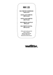
Multimètre digital portable 5000 points, avec entrées courant
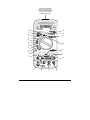
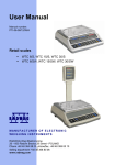
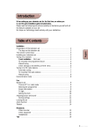
LEGENDE / LEGEND / BESCHREIBUNG / LEGENDA / LEYENDA
1
2
3
4
5
6
7
8
9
10
11
Borne d’entrée (positions 12 à 20)
Entrée de référence du multimètre
Borne d’entrée: gammes 500 mADC et 500 mAAC+DC
Borne d’entrée: gammes 10 ADC et 10 AAC+DC
Changement de gamme: RANGE
Fonctions secondaires: AC+DC
Mesure de pics +/Gel de l’affichage
Activation du rétro-éclairage
Mémorisation automatique
Mise hors tension
12
13
14
15
16
17
18
19
20
21
22
Mesure de tensions AC: gammes 5 VAC à 750 VAC (basse impédance)
Mesure de tensions AC+DC: gammes 5 VAC+DC à 750 VAC+DC
Mesure de tensions DC: gammes 5 VDC à 1000 VDC
Mesure de tensions: gammes 500 mVDC et 500 mVAC+DC
Mesure de fréquence
Test de continuité
Mesure de résistance
Mesure de capacité
Testeur de diode
Mesure de courant: gammes 500 mADC et 500 mAAC+DC
Mesure de courant: gammes 10 ADC et 10 AAC+DC
1
2
3
4
5
6
7
8
9
10
11
Input terminal (positions from 12 to 20)
Multimeter reference input
Input terminal, ranges 500 mADC and 500 mAAC+DC
Input terminal, ranges 10 ADC and 10 AAC+DC
Range change: RANGE
Secondary functions: AC+DC
+/- Peak measurement
Display hold
Backlighting
Automatic storage
Power off
12
13
14
15
16
17
18
19
20
21
22
AC voltage measurement, ranges 5 VAC to 750 VAC (low impedance)
AC+DC voltage measurement, ranges 5 VAC+DC to 750 VAC+DC
DC voltage measurement, ranges 5 VDC to 1000 VDC
Voltage measurement, ranges 500 mVDC to 500 mVAC+DC
Frequency measurement
Continuity test
Resistance measurement
Capacitance measurement
Diode test
Current measurement, ranges 500 mADC and 500 mAAC+DC
Current measurement, ranges 10 ADC and 10 AAC+DC
1
2
3
4
5
6
7
8
9
10
11
Eingansbuchse (Stellungen von 12 bis 20)
COM-Eingangsbuchse
Eingangsbuchse: (∗) 500 mADC und 500 mAAC+DC
Eingangsbuchse: (∗) 10 ADC und 10 AAC+DC
Bereichsumschaltung: RANGE
Zweitfunktionen: AC+DC
+/- Peak-Messung
Anzeige Speicherung
Anzeige Hintergrundbeleuchtung
Anzeige Autospeicherung
Multimeter Ausschalten
12
13
14
15
16
17
18
19
20
21
22
Messung von AC-Spannungen: (∗) 5 VAC bis 750 VAC (∗∗)
Messung von AC+DC-Spannungen: (∗) 5 VAC+DC bis 750 VAC+DC
Messung von DC-Spannungen: (∗) 5 VDC bis 1000 VDC
Spannungsmessung: (∗) 500 mVDC und 500 mVAC+DC
Frequenzmessung
Durchgangsprüfung
Widerstandsmessung
Kapazitätsmessung
Diodentest
Strommessung: (∗) 500 mADC und 500 mAAC+DC
Strommessung: (∗) 10 ADC und 10 AAC+DC
(∗) Meßbereich
(∗∗) niedrige Impedanz
1
2
3
4
5
6
7
8
9
10
11
Boccola ingresso posizioni 12 a 20
Ingresso di riferimento del multimetro
Boccola ingresso portate 500 mADC e 500 mAAC+DC
Bocola ingresso portate 10 ADC e 10 AAC+DC
Cambiamento di portata: RANGE
Funzioni secondarie: AC+DC
Reti Peak +/Blocco lettura su display
Retroiluminazione del display
Memorizzazione automatica
Spegnimento
12
13
14
15
16
17
18
19
20
21
22
Misura di tensione AC: portate da 5 VAC a 750 VAC (bassa impedenza)
Misura di tensione AC+DC: portate da 5 VAC+DC a 750 VAC+DC
Misura di tensione DC: portate da 5 VDC a 1000 VDC
Misura di tensione: portate da 500 mVDC a 500 mVAC+DC
Misura di frequenza
Test di continuitá
Misura di resistenza
Misura di capacitá
Test diodo
Misura di corrente: portate 500 mADC e 500 mAAC+DC
Misura di corrente: portate 10 ADC e 10 AAC+DC
1
2
3
4
5
6
7
8
9
10
11
Borne de entrada calibres 12 a 20
Entrada de referencia del multímetro
Borne de entrada calibres 500 mADC y 500 mAAC+DC
Borne de entrada calibres 10 ADC y 10 AAC+DC
Cambio de calibre: RANGE
Fonctiones segundarias: AC+DC
Medidas de peak +/Memorización de la representación visual
Retroiluminación
Memorización automatica
Puesta fuera de servicio
12
13
14
15
16
17
18
19
20
21
22
Medida de tensiones AC: calibres 5 VAC a 600 VAC (baja impedancia)
Medida de tensiones AC+DC: calibres 5 VAC+DC a 750 VAC+DC
Medida de tensiones DC: calibres 5 VDC a 1000 VDC
Medida de tensiones: calibres 500 mVDC y 500 mVAC+DC
Medida de frecuencia
Test de continuidad
Medida de resistencias
Medida de capacidades
Test diodo
Medida de corrientes: calibres 500 mADC y 500 mAAC+DC
Medida de corrientes: calibres 10 ADC y 10 AAC+DC
Multimètre digital portable 5000 points, avec entrées courant
Chapter II
USER’S MANUAL
CONTENTS
1.
GENERAL INSTRUCTIONS ...................................................................................................................16
1.1.
Precautions and safety measures ...................................................................................................16
1.1.1. Preliminary...................................................................................................................................16
1.1.2. During use ...................................................................................................................................16
1.1.3. Symbols.......................................................................................................................................17
1.1.4. Instructions ..................................................................................................................................17
1.2.
Protection mechanisms ...................................................................................................................18
1.3.
Safety mechanisms .........................................................................................................................18
1.4.
Warranty..........................................................................................................................................18
1.5.
Maintenance and metrological verification ......................................................................................18
1.6.
Unpacking - Repackaging ...............................................................................................................18
2.
DESCRIPTION........................................................................................................................................19
2.1.
Selector switch ................................................................................................................................19
2.2.
Keypad ............................................................................................................................................19
2.3.
Display.............................................................................................................................................19
2.4.
Power supply ...................................................................................................................................19
2.5.
Input terminals .................................................................................................................................19
3.
GETTING STARTED...............................................................................................................................20
3.1.
Connecting the test leads ................................................................................................................20
3.2.
Switching on the instrument ............................................................................................................20
3.3.
Switching off the instrument ............................................................................................................20
3.4.
Special configuration .......................................................................................................................20
3.5.
Multimeter maintenance ..................................................................................................................20
3.5.1. Fuse self-test ...............................................................................................................................20
3.5.2. Battery self-test............................................................................................................................21
3.5.3. Replacing the battery or fuses.....................................................................................................21
3.5.4. Cleaning ......................................................................................................................................21
3.5.5. Storage ........................................................................................................................................21
4.
FUNCTION DESCRIPTION ....................................................................................................................22
4.1.
RANGE / AC+DC key ......................................................................................................................22
4.1.1. ADPDC / ADPAC+DC Position....................................................................................................22
4.1.2. 500 mADC / 500 mAAC+DC Position .........................................................................................22
4.1.3. 10 ADC / 10 AAC+DC Position....................................................................................................23
4.2.
+/- Peak key ....................................................................................................................................23
4.3.
MEM / AUTO MEM key ..................................................................................................................23
4.4
key............................................................................................................................................23
5.
SOFTWARE KIT (optional) ....................................................................................................................24
6.
TECHNICAL SPECIFICATIONS .............................................................................................................25
6.1.
General............................................................................................................................................25
6.2.
Characteristics.................................................................................................................................25
6.2.1. DC voltages .................................................................................................................................25
6.2.2. AC voltages (AC and AC+DC).....................................................................................................25
6.2.3. DC current ...................................................................................................................................26
6.2.4. AC currents (AC+DC) ..................................................................................................................26
6.2.5. Resistance / Continuity test .........................................................................................................26
6.2.6. Capacitance.................................................................................................................................27
6.2.7. Diode threshold voltage measurement........................................................................................27
6.2.8. Frequencies.................................................................................................................................27
6.2.9. Safety ..........................................................................................................................................27
6.2.10. General information .................................................................................................................28
6.2.11. Environment ............................................................................................................................28
6.2.12. EMC.........................................................................................................................................28
6.3.
Accessories .....................................................................................................................................29
6.3.1. Supplied with the multimeter .......................................................................................................29
6.3.2. Optional .......................................................................................................................................29
5000-count portable digital multimeter, with current inputs
15
Chapter II
1.
GENERAL INSTRUCTIONS
You are the new owner of a 5000 ct portable digital multimeter and we thank you for your
choice.
This instrument complies with the specification set out in the IEC 61010-1 + A1 + A2,
concerning safety requirements for electronic measuring apparatus. To get the best service
from this instrument, read carefully this user's manual and respect the detailed safety
precautions.
The contents of this manual must not be reproduced in any form whatsoever without our
consent.
1.1.
Precautions and safety measures
1.1.1. Preliminary
- This device can be used for measurements on category ΙΙΙ installations, for voltages
never exceeding 600 V (AC or DC) relative to the earth.
- Definition of overvoltage categories (see. publication IEC 664-1) :
CAT I : The CAT I circuits are protected by safety measures limiting transient
overvoltages to appropriate low level.
Example : protected electronic circuits
CAT II : The CAT II circuits are power supply circuits of appliances or portable
equipment with transient overvoltages of an average level.
Example : appliances and portable equipment
CAT III : The CAT III circuits are power supply circuits of power equipment with
high transient overvoltages.
Example : fixed installation or industrial equipment
CAT IV : The CAT IV circuits may comprise very high transient overvoltages.
Example : primary supply level
∗ When using this multimeter, the user must observe all normal safety rules concerning:
- protection against the dangers of electric current.
- protection of the multimeter against misuse.
∗ For your own safety, only use the test probes supplied with the instrument and,
check, before use, that they are in good working condition.
1.1.2. During use
∗ Test equipment risk assessment : Users of this equipment and/or their employers
are reminded that Health and Safety Legislation requires them to carry out a valid
risk assessment of all electrical work so as to identify potential sources of electrical
danger and risk of electrical injury such as from inadvertent short circuits. Where the
assessment show that the risk is significant then the use of fused test leads
constructed in accordance with the HSE guidance note GS38 "Electrical Test
Equipment for use by Electricians" should be used.
∗ Never exceed the protection limit values indicated in the specifications for each type of
measurement.
16
5000-count portable digital multimeter, with current inputs
Chapter II
∗ When the multimeter is linked to measurement circuits, do not touch unused
terminals.
∗ When the range of the value to be measured is unknown, check that the range initially
set on the multimeter is the highest possible or, wherever possible, choose the
autoranging mode.
∗ Before changing functions, disconnect the test leads from the circuit under test.
∗ In TV repair work, or when carrying out measurements on power switching circuits,
remember that high amplitude voltage pulses at the test points can damage the
multimeter. Use of a TV filter will attenuate any such pulses.
∗ Never perform resistance or continuty measurements on live circuits.
1.1.3. Symbols
Warning: Risk of danger.
Refer to the operating manual to find out the nature of the potential hazards
and the action necessary to avoid such hazards.
Attention : Risk of electrical shock
Earth terminal
Equipment protected throughout by double insulation.
The rubbish bin with a line through it means that in the European Union, the
product must undergo selective disposal for the recycling of electric and
electronic material, in compliance with Directive WEEE 2002/96/EC.
Conforms CE
Power supply : 9 V (6LF22) battery
1.1.4. Instructions
∗ Before opening up the instrument, always disconnect from all sources of electric
current and make sure you are not charged with static electricity, which may destroy
internal components.
∗ Fuses must be replaced with fuses of the same rating and type.
∗ Any adjustment, maintenance or repair work carried out on the multimeter while it is
live should be carried out only by appropriately qualified personnel, after having
taken into account the instructions in this present manual.
A "qualified person" is someone who is familiar with the installation, construction
and operation of the equipment and the hazards involved. He is trained and
authorized to energize and de-energize circuits and equipment in accordance with
established practices.
∗ When the instrument is opened up, remember that some internal capacitors can
retain a dangerous potential even after the instrument is switched off.
∗ If any faults or abnormalities are observed, take the instrument out of service and
ensure that it cannot be used until it has been checked out.
∗ It is recommended to remove the battery from the instrument if not used.
5000-count portable digital multimeter, with current inputs
17
Chapter II
1.2.
Protection mechanisms
This instrument is fitted with various protection mechanisms :
∗ Varistor protection for limiting transients of over 1100 V at the VΩ terminal,
particularly 6 kV pulse streams as defined by the French standard IEEE 587.
∗ A PTC (positive temperature coefficient) resistor protects against permanent
overvoltages of up to 600 V during resistance, capacitance, continuity and diode test
measurements. This protection is reset automatically after overload.
∗ Two HBC fuses provide protection up to 600 V during measurements of intensity
type.
1.3.
∗
An IP protection rating of 40.
∗
Maximum protection beteen mA and 10 A input terminals : 500 V.
Safety mechanisms
∗ The battery unit cannot be accessed without first disconnecting the measuring leads.
∗ When measuring voltages above 24 V, the sign blinks
∗ When measuring voltages above 10 A, the sign blinks
intermittent audible signal warns the user.
on the display.
on the display and an
∗ If the maximum range is repeatedly exceeded, an intermittent audible signal warns
the user in volt (DC and AC+DC) and current (DC and AC+DC) functions.
1.4.
Warranty
This equipment is warranted against any defects of manufacture or materials according to
the general conditions of sale.
During the warranty period (3 years), defective parts will be replaced, the manufacturer
reserving the right to repair or replace the product. In the event of the equipment being
returned to the distributor or to a local agency, carriage to the centre shall be payable by
the customer. The warranty does not cover the following :
1.
2.
3.
4.
5.
1.5.
Repairs necessitated by misuse of the equipment or use in association with
incompatible equipment.
Modification of the equipment or any related software without the explicit authorization
of the manufacturer.
Repairs necessitated by attempts to repair or maintain the product made by a person
not approved by the manufacturer.
Adaptation to a specific application not provided for in the specifications of the
equipment or the user manual.
Damage after a drop, a shock or flooding.
Maintenance and metrological verification
Return your instrument to your distributor for any work to be done within or outside the
guarantee.
1.6.
Unpacking - Repackaging
This equipment has been fully checked out mechanically and electrically before shipping.
All precautions have been taken to ensure that the instrument arrives at its destination
undamaged. However, it is advisable to carry out a rapid check for damage sustained in
shipping. If there is any evidence of damage, make this known immediately to the shipper.
*
18
Should you need to return the multimeter, preferably use the original packaging and
indicate the reasons as clearly as possible on an accompanying note.
5000-count portable digital multimeter, with current inputs
Chapter II
2.
DESCRIPTION
This compact multimeter is a self-contained with an appropriate mechanical construction,
enables hand-held version, with a protective elastomer case. It is designed for a high
degree of user safety, maximum protection and unrivalled performance.
2.1.
Selector switch
This multimeter is a standalone, hand-held professional measuring instrument, capable of
measuring the following quantities (accessed by the twelve-position rotary selector switch):
∗
∗
∗
∗
∗
∗
∗
∗
∗
∗
∗
2.2.
AC voltages with AC (or RMS) capacitive coupling (Input impedance : 500 kΩ)
AC voltages with AC+DC (or TRMS) direct coupling
DC voltages
DC / AC+DC voltages, range 500 mV
AC currents with AC+DC (or TRMS) direct coupling
DC currents
resistance values
continuity (with beeper)
capacitance
diode threshold voltage
frequencies
Keypad
A four-key keypad lets you :
∗ select the autoranging mode (RANGE / AC+DC key)
∗ store a value (MEM key)
∗ activate the positive or negative peaks (Pk +/- key)
∗ select a function derived from the main function, or switch on the multimeter again
after it has been shut down automatically (RANGE / AC+DC key)
∗ activate back lighting of the display unit (
key)
keys + switch to OFF).
∗ activate the RS232 link (Pk +/- and
2.3.
Display
This multimeter display provides :
∗ 5 000-count measurements (50 000-count Hz-measurement),
∗ function indicator (V, A, AC+DC, F, Hz, , Ω,
, AUTO, MEM,
) and
multiplicator (n, µ, m, k, M),
∗ battery discharged indicator BAT : approximately 12 hours of operation,
∗ clearly legible figures (11 mm high),
∗ an analogue readout of the parameter being measured through a 34-segment
bargraph,
∗ validation of the RS232 interface.
Display backlight when required in poor lighting conditions. Automatic switch-off.
2.4.
Power supply
This multimeter is powered by a standard 9 V battery (6LF22) which provides
approximately 500 hours of operation (on function VDC).
2.5.
Input terminals
Measurements are performed using two measuring leads supplied with the instrument
connected to input terminals 1, 2, 3 and 4, as indicated in section 3.1.
5000-count portable digital multimeter, with current inputs
19
Chapter II
3.
GETTING STARTED
3.1.
Connecting the test leads
Connect the black lead to the COM socket (for all measurements). Depending on the
position of the selector switch, connect the red lead as follows:
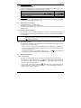
Rotary selector switch position
VLOW Z, VAC+DC, VDC, ADPDC (ADPAC+DC), Hz,
500 mADC (500 mAAC+DC)
10 ADC (10 AAC+DC)
Input terminal
, Ω,
,
VΩ
500 mA
10 A
RS232 lead :
Connect the RS232 optical interface (optional kit) to the top of the multimeter casing and
the DB9F plug to PC (COM port). Refer to § 5.
3.2.
Switching on the instrument
The selector switch is on the OFF position.
Turn the selector switch to the required function.
All segments of the display come on for a few seconds. The instrument is then ready for
measurements.
3.3.
Switching off the instrument
The instrument can be switched off manually by returning the selector switch to the OFF
position, or automatically after approximately half an hour if no key is pressed or the switch
is not operated.
)
Note
For user safety, automatic shutdown is disabled when a measured
magnitude (voltage/current) present at the input exceeds dangerous level
(
3.4.
indicator displayed).
Special configuration
To adapt the configuration of the instrument to the measurement environment, the user
can choose 50 Hz or 60 Hz rejection :
Switch on with the rotary switch while holding down the MEM key. The selection is
reversed from the last configuration, is displayed for two seconds and remains backed
up in non-volatile memory.
To initialise the RS232 communication, keep the Pk +/- and
pressed, then set the rotary switch to the selected position.
3.5.
keys simultaneously
Multimeter maintenance
3.5.1. Fuse self-test
This check can be carried out with the multimeter in use without opening up the casing.
position and short-circuit the 500 mA and
- 0.63 A fuse (F1) : set the rotary switch to the
VΩ sockets. The display should read approx. 0.001 V. If the digital display indicates an
overflow « .OL ». The fuse is blown.
position and short-circuit the COM and VΩ
- 10 A fuse (F2) : set the rotary switch to the
sockets. The display should read approx. 0.001 V. If the digital display indicates an
overflow « .OL ». The fuse is blown.
20
5000-count portable digital multimeter, with current inputs
Chapter II
3.5.2. Battery self-test
When the BAT indication appears on the display, the instrument still has approximately 12
hours of operation, but specifications can no longer be guaranteed.
Replace the battery.
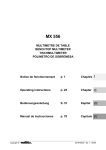
3.5.3. Replacing the battery or fuses
*
Caution !
Disconnect test leads from any circuit under test, turn the meter off
and remove test leads from the input terminals .
Use the following procedure:
1 - Disconnect test leads from any input terminals.
2 - Using an appropriate tool, slide off the case bottom of the instrument.
3 - Replace the battery or fuse (respect the value and the type).
4 - Replace the removable part.
F1 0.63 A HBC 18 kA / 600 V
F2 10 A HBC 50 kA / 600 V
Fuses must be replaced
by fuses of the same
rating and type.
6LF22
9 V BATTERY
*
Fitting the fuses :
Those fuses are correctly fitted ; those ones are not.
3.5.4. Cleaning
Clean the instrument using a damp cloth and soap. Never use abrasive or solvents.
3.5.5. Storage
To guarantee the measurement accuracy, after a long period storage in extreme
environment conditions, wait enough time for the instrument to acclimatise to the working
environment conditions (see environment specifications).
5000-count portable digital multimeter, with current inputs
21
Chapter II
4.
FUNCTION DESCRIPTION
4.1.
RANGE / AC+DC key
The RANGE key is operative in following positions of the selector switch :
VLOW Z, VAC+DC, VDC, Ω,
, Hz.
This key makes it possible :
• In AUTO (Autoranging) mode to switch to MANUAL mode (short press).
• In MANUAL mode, to select the next range (short press) or return to AUTO mode
(long press), the AUTO sign appears on the display.
This can be used to switch on the multimeter again after an automatic shutdown. It can also
be used to access secondary functions associated with the selector switch positions : mode
AC+DC.
The flowcharts below define these various functions.
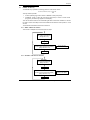
4.1.1. ADPDC / ADPAC+DC Position
This function is adapted for accessories with mV output.
ADPDC
DC voltage measurement
(Range 500 mVDC)
AC+DC key
ADPAC+DC
AC+DC voltage measurement (TRMS)
(Range 500 mVAC+DC)
The AC+DC sign
appears on the display.
AC+DC key
4.1.2. 500 mADC / 500 mAAC+DC Position
500 mADC
DC current measurement
(Range 50 mADC)
AC+DC key
500 mAAC+DC
AC+DC current measurement (TRMS)
(Range 500 mAAC+DC)
The AC+DC sign
appears on the display.
AC+DC key
22
5000-count portable digital multimeter, with current inputs
Chapter II
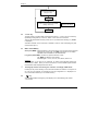
4.1.3. 10 ADC / 10 AAC+DC Position
10 ADC
DC current measurement
(Range 10 ADC)
AC+DC key
10 AAC+DC
AC+DC current measurement (TRMS)
(Range 10 AAC+DC)
The AC+DC sign
appears on the display.
AC+DC key
4.2.
+/- Peak key
The fast positive or negative peak measurement functions (> 1 msec.) can be accessed by
repeatedly pressing this key in the VDC, ADPDC, mADC and 10 ADC functions.
This key also desactivates the auto power-off, if it is pressed when switching on (“P-OFF”
is displayed).
Automatic shutdown of the instrument is disabled in order to avoid interrupting the peak
measurements (Pk +/-).
4.3.
MEM / AUTO MEM key
Short press (MEM) : Fixes the display on the current value. A second short press returns the
multimeter to normal mode. The “MEM” sign appears on the display.
The MEM mode is available on all measurements.
Long press (AUTO MEM) : Accesses or quits the “autostore” mode.
The “MEM” sign blinking on the display.
Affected ranges : VLOW Z, VAC+DC, VDC, ADPDC, ADPAC+DC
Autostore
Set the probes on the point to be measured. An audio signal indicates whether the
measurement is stable. When you remove the probes, a second audible signal indicates
that this stable value displayed has been stored.
)
The bargraph remains active during the "autostore” and display “MEM “mode.
Pressing this key when switching on the instrument enables the selection of a rejection of
50 or 60 Hz. The selection is reversed from the last configuration. It is displayed for 2
secs. and remains backed up in non-volatile memory.
4.4.
key
Activates/desactivates back lighting of the display unit. It automatically goes off after
≈ 60 seconds.
5000-count portable digital multimeter, with current inputs
23
Chapter II
5.
SOFTWARE KIT (optional)
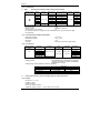
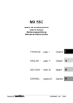
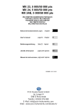
Connection of the kit and installation of the SX-DMM software :
With the software kit option, the multimeter can interface directly with a computer or PC:
1. Connect the optical plug at the top of the shockproof sheath. A mechanical fail-safe
device is provided on the left-hand side to prevent connection the wrong way round.
2. Plug the connector into one of the PC's "COM" ports.
3. Keep the "Pk +/-" and "
" multimeter keys pressed down and then move the switch
from the "OFF" position to the position required.
The digital display briefly indicates "RS232".
RS232
optical connector
Plug
PC
Mechanical
fail-safe
device
COM
RS232
interface
cable
Multimeter with its sheath
4. Install the SX-DMM software on the PC using the 2 floppy disks.
5. Start up the software to perform data acquisition and to take advantage of the various
display possibilities such as cursors, curves, tables, etc.
24
5000-count portable digital multimeter, with current inputs
Chapter II
6.
TECHNICAL SPECIFICATIONS
6.1.
General
Only the values assigned tolerances or given limits are guaranteed values. Values without
tolerances are given for information only, without guarantee (standard NFC 42670). The
measurement errors must be considered in an environment of reference temperature (refer to §
6.2.11).
It is essential that all measuring instruments are regularly calibrated.
6.2.
Characteristics
Accuracy is ± [% reading (R) + number of digits (D)].
{Accuracy : ‘’n %R + n D’’ means ‘’n % of the reading + n digits’’ }
6.2.1. DC voltages
Selector switch
position
ADPDC
VDC
Ranges
500 mVDC
5 VDC
50 VDC
500 VDC
1000 VDC
Accuracy
Input impedance
10 MΩ
11 MΩ
Protection (∗)
Resolution
0.1 mVDC
1 mVDC
10 mVDC
100 mVDC
1 VDC
± 1100 VPEAK
775 Vrms
0,3 % R + 2 D
10 MΩ
(∗) Acceptance permanent max. voltage
Number of points :
Range selection :
5 000
automatic or manual for the 5 V, 50 V,
500 V, 1000 V ranges
Common mode rejection :
at 50 and 60 Hz, better than 120 dB
Serial mode rejection :
at 50 and 60 Hz, better than 60 dB
Intermittent signal sounds and « OL » on the display in case of range overpassing.
For measurements performed on alternative signals, the selected range must tally with the max.
value of the signal peak.
Additional error in Pk +/- mode for a pulse width of ≥ 1 ms : 1 % R ± 50 D
6.2.2. AC voltages (AC and AC+DC)
Switch
Range
position
Input
Protection
impedance
(*)
40Hz to 1 kHz
1 to 4 kHz
500 kΩ
± 1100 Vpk
775 Vrms
1%L+3D
1%L+3D
± 1100 Vpk 1.5 % L + 3 D
775 Vrms
VLOW Z
5 VAC
50 VAC
500 VAC
ADPAC+DC
500 mVAC+DC
10 MΩ
//100 pF
5 VAC+DC
11 MΩ
VAC+DC
50 VAC+DC
500 VAC+DC
Accuracy
750 VAC
10 MΩ
Resolution
4 to 20 kHz 20 to 50 kHz 50 to 100 kHz
2%L+3D 3%L+3D
5%L+3D
1 mVAC
10 mVAC
100 mVAC
-
-
-
-
1 mVAC
-
-
-
-
0.1 mVAC+DC
5%L+3D
10 mVAC+DC
100 mVAC+DC
-
1 VAC+DC
1 mVAC+DC
± 1100 Vpk
775 Vrms
1%L+3D
1%L+3D
750 VAC+DC
-
2%L+3D 3%L+3D
-
-
(∗) Acceptance permanent max. voltage
Specifications applicable from 10 % to 100 % of the range for a sinusoidal signal in band 40 Hz
to 20 kHz and from 20 % to 100 % of the range in band 20 kHz to 100 kHz.
Number of points :
5 000
Range selection :
automatic or manual for the 5 V, 50 V,
500 V, 750 V ranges
Common mode rejection :
at 50 and 60 Hz, better than 60 dB
Additional error according to crest factor :
0.5 % for a crest factor of 2 to 3
1 % for a crest factor of 3 to 6
Intermittent signal sounds and « OL » on the display in case of range overpassing.
5000-count portable digital multimeter, with current inputs
25
Chapter II
6.2.3. DC current
Selector switch position
Ranges
Accuracy
Max volt. drop Protection Fuses (∗) Resolution
500 mADC
500 mADC 0.3 % R + 2 D
< 600 mV
600 VRMS F1 + F2 100 µADC
1%R+2D
< 700 mV
600 VRMS
F2
10 mADC
10 ADC
10 ADC (∗∗)
(∗) Refer to fuse specifications section 3.5.3.
(∗∗) Acceptance 20 A overload during 30 s. max, observing a 5 min break at least between 2
measurements.
Beyond 7 A, the measurement is limited to one minute.
Number of points : 5 000
« OL » on the display (range 500 mADC only) and intermittent signal sounds in case of range overpassing.
For measurements performed on alternative signals, the selected range must tally with the max. value of
the signal peak.
Additional error in Pk +/- mode for a pulse width of ≥ 1 ms : 1 % R ± 50 D
6.2.4. AC currents (AC+DC)
Selector switch
position
Ranges
500 mAAC+DC
10 AAC+DC (∗∗)
Accuracy
Max.
volt.drop
Protection
500 mAAC+DC
40 Hz to 10 kHz : 10 kHz to 30 kHz : 5 < 600 mV
1.5 % R + 2 D
%R+2D
600 VRMS
10 AAC+DC
40 Hz to 2 kHz : 2.52 kHz to 10 kHz : 5 < 700 mV
%R+2D
%R+2D
600 VRMS
Fuses
(∗)
Resolution
F1 + F2 100 µAAC+DC
F2
Max.
crest
1A
10 mAAC+DC
(∗) Refer to fuse specifications section 3.5.3.
(∗∗) Acceptance 20 A overload during 30 s. max, observing a 5 min break at least between 2
measurements.
At 10 A, the measurement is limited to a period of 30 minutes.
500 mAAC+DC range:
Specifications applicable from 10 % to 100 % of the range for a sinusoidal signal in band 40 Hz to 30 kHz.
10 AAC+DC range:
Specifications applicable from 10 % to 100 % of the range for a sinusoidal signal in band 40 Hz to 2 kHz
and 20 % to 100 % of the range in band 2 kHz to 10 kHz.
Number of points : 5 000
Additional error according to crest factor :
0.5 % for a crest factor of 2 to 3
1 % for a crest factor of 3 to 6
« OL » on the display (range 500 mAAC+DC only) and intermittent signal sounds in case of range
overpassing.
*
blinks and an intermittent signal sounds (10 ADC and 10 ADC+DC ranges) in case of
measurements over 10 ADC and 10 ADC+DC.
6.2.5. Resistance / Continuity test
Selector switch
Ranges
Accuracy
0.3 % R + 3 D
500 Ω
500 Ω
0.3 % R + 3 D
5 kΩ
Ω
50 kΩ
500 kΩ
0.5 % R + 3 D
5 MΩ
1%R+5D
50 MΩ
(∗) Overload protection can be reset automatically.
Measur. current
1 mA
1 mA
100 µA
10 µA
1 µA
100 nA
50 nA
Protection (∗)
600 VRMS
Resolution
0.1 Ω
0.1 Ω
1Ω
10 Ω
100 Ω
1 kΩ
10 kΩ
Number of points :5 000
Range selection : auto or manual (fixed in continuity mode)
Maximum open circuit voltage : 7 V
Detection threshold in continuity mode : 10 Ω to 15 Ω
Response time in continuity mode : 1 ms
For measurements in 5 MΩ and 50 MΩ ranges, the use of shielded and very short connection is highly
recommended.
26
5000-count portable digital multimeter, with current inputs
Chapter II
6.2.6. Capacitance
)
Note
Discharge all capacitors before taking measurements.
Selector switch
position
Ranges
Accuracy
Measurement
current
50 nF
100 nA
500 nF
1 µA
5 µF
10 µA
50 µF 1 % R + 2 D
100 µA
500 µF
1 mA
5000 µF
1 mA
50 mF 2 % R + 2 D
1 mA
Max measurement Protection Resolution
time
(∗)
<1s
10 pF
<1s
100 pF
<1s
1 nF
10 nF
<1s
600 VRMS
<2s
100 nF
1 µF
≈ 3 s/mF
10 µF
≈ 3 s/mF
(∗) Overload protection can be reset automatically.
Number of points :
5 000
Range selection :
automatic or manual
Maximum open circuit voltage :
7V
For measurements in 50 nF range, the use of shielded and very short connection is highly
recommended.
6.2.7. Diode threshold voltage measurement
Measurable voltages :
Measurement current :
Resolution :
Protection :
0 to 1.999 V
1 mA +/- 20 %
1 mV
600 VRMS, can be reset automatically
6.2.8. Frequencies
Selector switch
position
Hz
Ranges
Accuracy
0.62 to 5 Hz
5 to 50 Hz
50 to 500 Hz
500 Hz to 5 kHz
5 to 50 kHz
50 to 500 kHz
Input
impedance
0.03 % R + 1 D
10 MΩ
(VAC+DC)
Protection
± 1100 VPEAK
775 Vrms
0.05 % R + 1 D
Resolution
0.0001 Hz
0.001 Hz
0.01 Hz
0.1 Hz
1 Hz
10 Hz
50 000
The measurement is realised by the capacitive
coupling. The frequency meter is automatically
positioned on 5 V range.
Voltage range manual selection possible, if necessary.
Number of points :
Range selection :
Sensitivity
Range
0.62 Hz to 5 kHz (*)
5 kHz to 50 kHz
50 kHz to 500 kHz
(*) square signals
)
5 V to 500 V
2 % of range
5 % of range
10 % of range
750 V
100 V
250 V
-
In this switch position, only the voltage frequency can be measured.
6.2.9. Safety
IEC 61010-1 + A1 + A2
Insulation : class 2
Pollution degree : 2
Indoor use, altitude < 2000 m
Installation category of input :
CAT III, 600 V max. to earth
5000-count portable digital multimeter, with current inputs
27
Chapter II
6.2.10. General information
Mechanical
Dimensions
Weight (inc. battery)
Casing and circuit
170 x 80 x 35 mm
285 g
self-extinguishing materials
Packaging
Dimensions
Weight
230 x 155 x 65 mm
385 g
Power supply
Power requirements
Low battery indication
single 9 V alkaline battery (6LF22)
BAT is displayed when the battery
voltage drops below operating voltage
500 hours approx. in VDC mode
Battery life
Display
Liquid crystal display comprising
- a 50 000-count display + sign (digits 11 mm high)
- a 34-bar analogue bargraph display
- appropriate units for each type of measurement
- triggered mode indicators (storage, ranging, ...)
- battery discharged indicator
Measurement rate
Digital display
Bargraph
2 measurements/s
20 measurements/s
6.2.11. Environment
Reference temperature
Limit range of operation
Not specified rated range of use
Storage temperature range
Temperature coefficient
Relative humidity
Water-tightness
Max. influence in electro-magnetic fields at
3 V/m acc. to EN 61000-4-3
23°C ± 5°C
0°C to 50°C
-10°C to 0°C and 50°C to 55°C
-20°C to 70°C
max. 0.1 x (accuracy) / °C
0 to 80 % from 0 to 35°C
(70 % max. for ranges from 5 and 50 MΩ)
0 to 70 % from 35°C to 50°C
IP 40
± 300 D in VDC and VAC ranges
± 200 D in IDC and IAC ranges
± 200 D in Ohm range
6.2.12. EMC
This apparatus was designed in accordance with the EMC standards in force and its
compatibility has been tested accordance with the following standards :
• Emission EN 61326-1
• Immunity EN 61326-1
The product conforms to the prescriptions of the European directive low voltage directive
73/23/EEC and the EMC directive 89/336/EEC, amended by 93/68/EEC.
28
5000-count portable digital multimeter, with current inputs
Chapter II
6.3.
Accessories
6.3.1. Supplied with the multimeter
One set of test leads with safety probes
One 6LF22 9 V battery
One user’s manual
Protective elastomer case with RS232 window
AL0042
906129650
HX0010
6.3.2. Optional
Communication kit
Acquisition Software (part. nr. SX-DMMC)
RS232 lead (DB9F) (part. nr. HX2002)
SX-DMMK
Software
Calibration software
SX-MX26CAL
Connection
RS232 lead (DB9F)
HK2002
Probes
EHT 3 kVAC/DC
EHT 30 kVDC
HT0203
HT0212
Type K thermocouple, 1 mV/°C, general purpose
and surface type, -25°C to +350°C
HK0210N
Optical tachometer, 100 rpm to 60 000 rpm
HA1237
Current clamps
Range 200 AAC, 1 AAC/1 mVAC, max cable ∅ 20 mm, connection : sockets
Range 200 AAC, 1 AAC/10 mVAC, max cable ∅ 20 mm, connection : sockets
Range 600 ADC, 600 AAC, max cable ∅ 30 mm, connection : sockets
Range 1000 ADC, 600 AAC, max cable ∅ 43 mm, connection : sockets
AM0014N
AM0016N
AM0600N
AM1000N
Shunts
30 ADC / 300 mV, ± 0.5%
50 ADC / 50 mV, ± 0.5%
300 ADC / 30 mV, ± 0.5%
HA0170
HA0512
HA0300
Fuses
Fuse 6.3 x 32 mm, 10 A, 50 kA / 600 V
Fuse 6.3 x 32 mm, 0.63 A, 18 kA / 600 V
AT0084
AT0519
Miscellaneous
Carrying bag
Carrying case (Nr. 30)
Set of test leads with safety probes (bent bananas)
AE0190
HX0009
AG0475A
5000-count portable digital multimeter, with current inputs
29