1
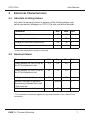
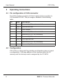
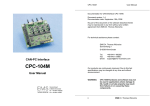
CAN-PC Interface
CPC-PCIe
User manual
Thomas Wünsche
CPC-PCIe
User Manual
User manual CPC-PCIe V2
Document version:
Documentation date:
2.00
August 10th, 2010
No part of this document or the software described herein may be
reproduced in any form without prior written agreement from EMS Dr.
Thomas Wünsche.
For technical assistance please contact:
EMS Dr. Thomas Wünsche
Sonnenhang 3
D-85304 Ilmmünster
Tel. +49-8441-490260
Fax +49-8441-81860
Our products are continously improved. Due to this fact specifications may
be changed at any time and without announcement.
WARNING:
2
CPC-PCIe hardware and software may not be used in
applications where damage to life, health or private
property may result from failures in or caused by
these components.
EMS Dr. Thomas Wünsche
CPC-PCIe
User Manual
Content
1
Overview
4
1.1 Attributes
1.2 General Description
1.3 Ordering Information
4
4
5
2
Programming Interface
6
3
Electrical Characteristics
7
3.1 Absolute Limiting Values
3.2 Nominal Values
7
7
Operating Instructions
8
4.1 Pin Configuration of CAN Connector
4.2 Configuration
4.3 Installation
8
8
9
4.
EMS Dr. Thomas Wünsche
3
User Manual
1
CPC-PCIe
Overview
1.1 Attributes
• CAN Interfaces for industrial applications
• Compact size for PCIe x1 slots
• CiA DS 102 and ISO 11898 compatible physical layer
• Equipped with up to four CAN controller NXP SJA1000
• Extended ESD-protection of the CAN controller
• Galvanic decoupling between PC and CAN bus (optional)
• Galvanic decoupling between individual CAN channels (optional)
• Easy programming based on direct mapping of CAN controller
registers into PC memory area
1.2 General Description
CPC-PCIe is a PCI Express plug-in card for the CAN bus. Designed
for industrial series applications CPC-PCIe has a robust and cost
efficient layout. CPC-PCIe supports up to four CAN controller of type
NXP SJA1000.
CPC-PCIe maps the CAN controller into the PC address space and
thus allows access to CAN messages with low latency. Existing
software for the supported CAN controller can easily be adapted.
With CPC-PCIe the CAN communication may be handled either in
interrupt controlled or in polled mode.
CPC-PCIe can optionally be delivered with galvanic decoupling of
the CAN bus. The dual and four channel version has the additional
option of galvanic decoupling between the CAN channels.
4
EMS Dr. Thomas Wünsche
CPC-PCIe
User Manual
1.3 Ordering Information
10-11-200-20
10-11-201-20
10-11-210-20
10-11-211-20
10-11-212-20
10-11-230-20
10-11-232-20
EMS Dr. Thomas Wünsche
CPC-PCIe/SJA1000S
CAN plug-in board with one CAN controller
NXP SJA1000
CPC-PCIe/SJA1000S-GTIS
CAN plug-in board with one CAN controller
NXP SJA1000, galvanic decoupling
CPC-PCIe/SJA1000D
CAN plug-in board with two CAN controllers
NXP SJA1000
CPC-PCIe/SJA1000D-GTID
CAN plug-in board with two CAN controllers
NXP SJA1000, galvanic decoupling
CPC-PCIe/SJA1000D-GTI2S
CAN plug-in board with two CAN controllers
NXP SJA1000, individual galvanic decoupling
CPC-PCIe/SJA1000Q
CAN plug-in board with four CAN controllers
NXP SJA1000
CPC-PCIe/SJA1000Q-GTIS
CAN plug-in board with four CAN controllers
NXP SJA1000, individual galvanic decoupling
5
CPC-PCIe
User Manual
2
Programming Interface
CPC-PCIe is mapped into the PC memory space with a base
address assigned by the PC BIOS. The availability of the CAN
controller(s) int the memory area makes the CAN communication
direct and provides a low latency time. The card is identified by the
following parameters:
Vendor ID
Device ID
Subvendor ID
Subsystem ID
: 0x10B5
: 0x9030
: 0x10B5
: 0x4000
A PCIe/PCI bridge is used to establish a local PCI bus on the
interface card. This PCI bus is automaticly enumerated by the
operating system at boot time. Furthermore CPC-PCIe incorporates
a PLX9030 PCI to local bus bridge. BAR0 of the PCI configuration
space register points to the bridge registers, whereas BAR2 plus an
offset of 0x400 points to the first SJA1000 CAN controller. At offset
0x600, 0x800 and 0xA00 of BAR2 the optional second, third and
fourth SJA1000 CAN controller can be accessed.
Please contact EMS Dr. Thomas Wünsche for more detailed
information about the programming interface of CPC-PCIe.
6
EMS Dr. Thomas Wünsche
CPC-PCIe
3
User Manual
Electrical Characteristics
3.1 Absolute Limiting Values
Any (also temporary) stress in excess of the limiting values may
cause permanent damage on CPC-PCIe and connected devices.
Parameter
Min.
Storage temperature
-20
80
°C
0
60
°C
-30
30
V
-
1
A
Operating temperature*
Voltage on the bus connections
Current across ground connection
Max. Unit
* Extended temperature range on demand
3.2 Nominal Values
Parameter
Min.
Typ.
Power supply on +3V3 Pins of
the PCIe expansion slot
3,1
3,3
3,5
V
Power supply on +12V Pins of
the PCIe expansion slot
11
12
13
V
Voltage on bus pins*
-30
-
30
V
-
1000V
-
V
-
16
-
MHz
Isolation voltage of galvanic
decoupling between host and
CAN potential
CAN controller clock frequency
Max. Unit
* This potential is measured against the ground potential of the related CAN
transceiver
EMS Dr. Thomas Wünsche
7
CPC-PCIe
User Manual
4
Operating Instructions
4.1 Pin configuration of CAN connector
The CAN interface connector (D-Sub 9 male) schema complies to
CiA Standard DS 102. The pin usage is detailed in the following
table:
1
Name
-
2
CAN_L CAN low bus line
3
CAN Ground
4
GND
-
5
-
Reserved by CiA, not connected
6
-
Reserved by CiA, not connected
7
CAN_H CAN high bus line
Reserved by CiA, not connected
Reserved by CiA, not connected
Pin
8
9
Description
Reserved by CiA, not connected
Reserved by CiA, not connected
4.2 Configuration
CPC-PCIe is a Plug and Play interface and therefore does not need
a configuration. The base address of the interface within the PC
memory and the interrupt used is assigned by the PC BIOS.
8
EMS Dr. Thomas Wünsche
CPC-PCIe
User Manual
4.3 Installation
CPC-PCIe may be installed in an empty expansion slot on the
motherboard of your IBM compatible computer. To avoid damage
please pay attention to the following hints:
WARNING: Computer devices and components are sensitive
against static discharge. For this reason keep CPC-PCIe in the
antistatic cover until installing. Just before removing CPC-PCIe from
the protection cover touch the metal case of your computer.
Avoid damage by achieving equal potential between all devices on
the CAN before plugging the connection.
To the rear side connector of CPC-PCIe only CAN networks with a
connector and elecrical character complying with CiA DS-102 may
be attached.
PC interface and CAN bus are not galvanic decoupled in the
standard version of CPC-PCIe. Use in systems with diverging
ground potential of PC and CAN bus is not permitted in this case.
Besides the instructions mentioned in this manual carefully observe
the instructions in your coumputers user manual.
If you are not sure about the installation please contact EMS Dr.
Thomas Wünsche.
EMS Dr. Thomas Wünsche
9
CPC-PCIe
User Manual
Execute the following steps for installation:
• Disconnect your computer from the power line.
• Open the case of your computer and remove the cover of the
expansion slot rear panel.
• Insert CPC-PCIe carefully into the PCIe slot. Therefore take the
card at its top corners and shift it down into the slot equally. Push
onto the upper side of CPC-PCIe to achieve correct seat in the slot.
If the card can not be inserted without problems, please don't
use extensive force. Remove the card and retry.
• Fix the mounting screw and close the PC housing. Connect the
required cables.
EMS Dr. Thomas Wünsche
10