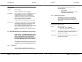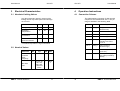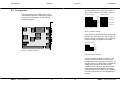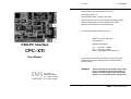
1
CPC-XTI
User Manual
Documentation for CAN-Interface CPC-XTI.
Document version 1.3.
Documentation date: January 17th, 2005.
No part of this document or the software described herein
may be reproduced in any form without prior written
agreement from EMS Dr. Thomas Wünsche.
For technical assistance please contact:
EMS Dr. Thomas Wünsche
Sonnenhang 3
D-85304 Ilmmünster
CAN-PC Interface
Tel. +49-8441- 490260
Fax +49-8441- 81860
Email: [email protected]
CPC–XTI
User Manual
Our products are continuously improved. Due to this fact
specifications may be changed at any time and without
announcement.
WARNING:
EMS
THOMAS WÜNSCHE
Sonnenhang 3
D-85304 Ilmmünster
Tel +49-8441-490260
Fax +49-8441-81860
ii
CPC-XTI hardware and software may not be
used in applications where damage to life,
health or private property may result from
failures in or caused by these components.
EMS Dr. Thomas Wünsche
User Manual
CPC-XTI
CPC-XTI
User Manual
THIS PAGE INTENTIONALLY LEFT BLANK
Contents
1 Overview . . . . . . . . . . . . . . . . . . . . . . . . 1
1.1
1.2
1.3
1.4
Attributes . . . . . .
General description .
Sample Applications
Ordering Information
.
.
.
.
.
.
.
.
.
.
.
.
.
.
.
.
.
.
.
.
.
.
.
.
.
.
.
.
.
.
.
.
.
.
.
.
.
.
.
.
.
.
.
.
.
.
.
.
.
.
.
.
.
.
.
.
.
.
.
.
.
.
.
.
1
1
2
3
2 Software . . . . . . . . . . . . . . . . . . . . . . . . 4
2.1
2.2
2.3
2.4
2.5
2.6
Functions of CPC-XTI . . . . . . . . . . . . . . . 4
Application program: Realization Concepts . . . . 4
Synchronous Interface . . . . . . . . . . . . . . . 5
Asynchronous Interface . . . . . . . . . . . . . . 5
Data Structures and Library Functions . . . . . . . 6
MS-Windows Driver Additional Information . . . . 15
3 Electrical Characteristics . . . . . . . . . . . . . . 17
3.1 Absolute Limiting Values . . . . . . . . . . . . . 17
3.2 Nominal Values . . . . . . . . . . . . . . . . . . 17
4 Operation Instructions . . . . . . . . . . . . . . . . 18
4.1 Connection Scheme. . . . . . . . . . . . . . . . 18
4.2 Configuration . . . . . . . . . . . . . . . . . . . 19
4.3 Installation . . . . . . . . . . . . . . . . . . . . . 21
EMS Dr. Thomas Wünsche
iii
iv
EMS Dr. Thomas Wünsche
User Manual
1
CPC-XTI
CPC-XTI
Overview
application in 8 bit slots CPC-XTI can be used
in space restricted conditions as well.
Designed for industrial series applications
CPC-XTI has a robust and cost efficient
construction.
1.1 Attributes
CPC-XTI offers a range of unique features
which make it valuable for many CAN based
applications:
•
•
•
•
•
•
•
•
•
•
•
•
User Manual
CAN-interface for industrial applications
Available with one or two CAN-channels
Compact size for 8-bit slots
CiA DS-102 and IS0 11898 compatible
physical layer
Smart system with fast integrated microcontroller Dallas DS80C320
Equipped with CAN controller Philips
PCA82C200 or SJA1000
Philips PCA82C251 CAN transceiver
for increased robustness
Extended ESD-protection of the CAN
transceiver(s)
Galvanic decoupling between PC and
CAN bus
Modular application interface with libraries for Borland C++, Borland Pascal
and Microsoft C
Optional MS-Windows driver with DLL
based API and VxD technology for high
communication throughput
Automatic address range detection by
memory managers.
CPC-XTI eases the development of
application software on the PC. The integrated
microcontroller takes load of the PC-CPU and
buffers and preprocesses CAN messages. A
high level programming interface with modular
design results in efficient software
development. A library of interface routines for
Borland C++, Borland Pascal and Microsoft C
is included.
CPC-XTI is shipped with one or two CAN
channels. For high volume applications cost
optimized versions without galvanic
decoupling and with PROM based code
storage are available.
Interrupt channels 3 - 7 are supported.
1.3 Sample Applications
The application area of CPC-XTI is wide.
Some sample applications are detailed in the
following and supported by corresponding
software:
• Online configuration of CAN networks
• Network setup and analysis
• Use of PCs as CAN nodes on the appli-
1.2 General description
cation level
CPC-XTI is a short PC plug-in board for the
CAN bus. With its small size and the possible
EMS Dr. Thomas Wünsche
• Visualisation of process parameters in
CAN based systems.
1
2
EMS Dr. Thomas Wünsche
User Manual
CPC-XTI
1.4 Ordering Information
10-04-201-20
10-04-211-20
CPC-XTI
2
User Manual
Software
The software consists of two parts. One part is
executed by the microprocessor inside
CPC-XTI. The application program runs on the
PC and makes use of the interface library.
CPC–104I/SJA1000S320-GTI
CAN plug-in board with
microcontroller Dallas 80C320
and 1 galvanically separated
CAN channel with Philips
SJA1000
2.1 Functions of CPC-XTI
CPC–104I/SJA1000D320-GTI
CAN plug-in board with
microcontroller Dallas 80C320
and 2 galvanically separated
CAN channels with Philips
SJA1000
CPC-XTI offers enhanced functionality for
CAN communication:
• Transmission and reception of
CAN-messages
• Filtering and buffering of received messages
• Measurement of bus-load
The functions of CPC-XTI are accessed
across the interface library of the PC.
2.2 Application program: Realization Concepts
The library of interface functions supports two
ways to implement the application program.
The synchronous mode complies with
conventional programming. The sequence of
program steps is given by the program
structure. Asynchronous mode allows event
driven programming similar to the way used in
graphical user interfaces.
EMS Dr. Thomas Wünsche
3
4
EMS Dr. Thomas Wünsche
User Manual
CPC-XTI
2.3 Synchronous Interface
main
program
command
initiation
wait for result
command
execution
by CPC-XTI
continue
command
initiation
further
program
execution
command
execution
by CPC-XTI
use result
EMS Dr. Thomas Wünsche
User Manual
2.5 Data Structures and Library Functions
Implementation of the main
program with synchronous
interface allows simple and
clearly arranged programs
with sequential control flow.
It is suitable mainly for simple
applications, which allow a
predefinition of events to
process. This is true if, for
example, only CAN
messages are to be received
or only bus load
measurement is to be
realized.
2.5.1
Data Structures
The following structures are declared in the
include file CPC.H.
Please notice that the structures and
functions described in the following refer
to the old DOS and Windows libraries and
are included in this manual for
compatibility reasons. The new structures
and functions are described within the
manual ‘CPC Series Development Kit for
MS Windows Environment’.
struct CPC_MSG
2.4 Asynchronous Interface
main
program
CPC-XTI
The asynchronous interface
provides enhanced flexibility
in reaction to events which
are not predictable in their
sequence of occurrence.
Communication objects can
be processed independent of
program state, reactions can
be configured flexible. For this
purpose every communication
object is handed on to a set of
handling functions. Such
functions are provided within
the programming library. The
application programmer can
add routines as required by
application purposes.
5
Declaration:
struct CPC_MSG {
unsigned char typ;
unsigned char length;
union {
unsigned char genericmsg[];
unsigned char textmsg[];
char versionmsg[];
char serialmsg[];
struct CPC_CAN_MSG canmsg;
unsigned char busloadmsg;
unsigned char canstatemsg;
struct CPC_CAN_PARAMS
can_params_msg;
};
};
Description:
CPC_MSG serves for parameter transfer
between application program and interface
library.
6
EMS Dr. Thomas Wünsche
User Manual
CPC-XTI
CPC-XTI
User Manual
struct CPC_CAN_MSG
struct CPC_INIT_PARAMS
Declaration:
struct CPC_CAN_MSG{
unsigned short id;
unsigned char length;
unsigned char overrun;
unsigned char msg[8];
};
Declaration:
struct CPC_INIT_PARAMS{
struct CPC_CAN_PARAMS
std_can_params;
unsigned char secure_transmit;
void interrupt (far * inthandler)();
};
Description:
CPC_CAN_MSG serves for transfer of CAN
messages between application program and
interface library
Description:
The global variable CPC_Init_Params, which
has this type, holds initialization parameters.
struct CPC_CAN_PARAMS
Declaration:
struct CPC_CAN_PARAMS{
unsigned char acc_code;
unsigned char acc_mask;
unsigned char btr0, btr1;
unsigned char outp_contr;
};
Description:
CPC_CAN_PARAMS defines initialization
values for the CAN controller in CPC-XTI
(type PCA82C200)
EMS Dr. Thomas Wünsche
7
8
EMS Dr. Thomas Wünsche
User Manual
2.5.2
CPC-XTI
Synchronous Functions
Syntax:
#include cpc.h
int CPC_CAN_Init(void);
Description:
CPC_CAN_Init() initialises the parameters of
the CAN controller within CPC-XTI. The
CAN-controller is set up with parameters
supplied in the global structure
CPC_Init_Params (declaration in cpc.h).
These parameters can be changed before the
call to CPC_CAN_Init(). CPC_CAN_Init is to
be called before data transmission across the
CAN is initiated.
–
CPC_Control
Syntax:
#include cpc.h
int CPC_Control(int);
Description:
CPC_Control() serves for setup of the message types to be transmitted from CPC-XTI
to the PC. The upper 6 bits select the type of
message, the lower 2 bits determine the
transmission behaviour. The properties that
can be influenced are described in cpc.h.
Return value:
Syntax:
#include cpc.h
void CPC_Exit(void);
Description:
CPC_Exit() is to be called before leaving the
application program. CPC_Exit() is in any case
to be used paired with CPC_Init().
Return value:
–
CPC_Get_Busload
Syntax:
#include cpc.h
int CPC_Get_Busload(void);
Description:
CPC_Get_Busload() measures the actual
bus-load and returns it as percentage of the
maximum bus load.
Return value: Actual bus load: 0 corresponds to 0%, 255
corresponds to 100% bus-load.
CPC_Get_Serial
–
EMS Dr. Thomas Wünsche
User Manual
CPC_Exit
CPC_CAN_Init
Return value:
CPC-XTI
Syntax:
#include cpc.h
char * CPC_Get_Serial(void);
Description:
CPC_Get_Serial returns the serial number of
the connected CPC-XTI module.
Return value: Pointer to a string with the serial number or
NULL in case of errors.
9
10
EMS Dr. Thomas Wünsche
User Manual
CPC-XTI
CPC-XTI
User Manual
CPC_Get_Version
CPC_Read_Msg
Syntax:
#include cpc.h
char * CPC_Get_Version(void);
Syntax:
#include cpc.h
void CPC_Read_Msg
(struct CPC_CAN_MSG *);
Description:
CPC_Get_Version returns the version number
of the connected CPC-PP module.
Description:
CPC_Read_Msg() receives a message from
the CAN. The received communication object
is stored in a structure of type
CPC_CAN_MSG, which is indicated by the
pointer passed on function call.
Return value: Pointer to a string with the version number or
NULL in case of errors.
CPC_Init
Syntax:
Description:
Return value:
Return value:
#include cpc.h
int CPC_Init(void);
CPC_Send_Msg
CPC_Init() initialises the communication with
CPC-XTI. CPC-XTI is initialised to standard
parameters, which are stored in the global
structure CPC_Init_Params (declaration in
cpc.h). These parameters can be changed on
demand before calling CPC_Init(). CPC_Init()
is to be called before using the other functions
of the interface library.
0
–1
for correct initialization,
for initialization errors.
EMS Dr. Thomas Wünsche
–
Syntax:
#include cpc.h
int CPC_Send_Msg
(struct CPC_CAN_MSG *);
Description:
CPC_Send_Msg() sends a message across
the CAN. The function call passes a pointer to
a structure of type CPC_CAN_MSG, which
contains the communication object to be
transmitted.
Return value:
11
12
–
EMS Dr. Thomas Wünsche
User Manual
CPC-XTI
2.5.3
CPC_Send_RTR
Syntax:
Description:
CPC-XTI
#include cpc.h
int CPC_Send_RTR
(struct CPC_CAN_MSG *);
User Manual
Functions for the Asynchronous Programming
Interface
CPC_Add_Handler
CPC_Send_RTR() transmits a
Remote-Transmission-Request message
across the CAN. The function call passes a
pointer to a structure of type CPC_CAN_MSG,
which contains the communication object to
be transmitted.
Syntax:
#include cpc.h
int CPC_Add_Handler(void (*handler)
(const struct CPC_MSG *));
Description:
CPC_Add_Handler() adds the handler
indicated by the pointer passed at function call
to the list of handlers which are executed on
any incoming CPC-XTI message.
Return value:
0
–1
Return
–
value: –
on error free execution,
if the list of handlers is full.
CPC_Remove_Handler
EMS Dr. Thomas Wünsche
13
Syntax:
#include cpc.h
int CPC_Remove_Handler(void (*handler)
(const struct CPC_MSG *));
Description:
CPC_Remove_Handler() removes the handler
indicated by the pointer passed at function call
from the list of handlers which are executed on
any incoming CPC-XTI message. If the
handler is contained more than once, the last
occurence is removed.
Return value:
0
–1
14
on error free execution,
if handler was not within the list.
EMS Dr. Thomas Wünsche
User Manual
CPC-XTI
CPC-XTI
User Manual
The installation program performs the
following actions:
CPC_Handle
Syntax:
#include cpc.h
struct CPC_MSG * CPC_Handle();
Description:
CPC_Handle() checks for availability of a new
message from CPC-XTI. If a message is
available, all asynchronous handlers are
called in the sequence of their entry position
with the new message as parameter.
CPC_Handle() returns immediately,
independant of the availability of a message.
• copy the files
• install entry for virtual device driver in
Return value: A pointer to a static memory area containing
the message is returned. This memory area
is overwritten during following calls to
CPC_Handle() and also on use of many of the
synchronous interface functions. If no
message is available, CPC_Handle() returns
NULL.
2.6 MS-Windows Driver Additional Information
Please notice: this subchapter refers to the
older version of the Windows Development
Kit. For information on the new version
please read the ‘CPC Series Development
Kit for MS Windows environment’ manual.
SYSTEM.INI (Windows9X)
2.6.2
Additional Functions
One additional function is necessary to
compensate the fact that the initialisation
structure is not directly accessible to the
application:
CPC_Get_Init_Params_Ptr
Syntax:
#include “cpc.h”
structure CPC_INIT_PARAMS
CPC_Get_Init_Params_Ptr(void);
Description:
This function provides access to the initialization structure, which is contained in the
Dynamic Link Library.
Return value: A pointer to the initialization structure in the
Dynamic Link Library.
The software functionality and interface equals
the MS-DOS version. Differences exist in the
software setup and a few additional functions.
2.6.1
Installation
The installation is provided by the setup
program. Run SETUP.EXE from delivery disk.
EMS Dr. Thomas Wünsche
15
16
EMS Dr. Thomas Wünsche
User Manual
3
CPC-XTI
Electrical Characteristics
CPC-XTI
4
3.1 Absolute Limiting Values
User Manual
Operation Instructions
4.1 Connection Scheme
Any (also temporary) stress in excess of the
limiting values may cause permanent damage
on CPC-XTI.
The CAN-interface-connector (D-Sub 9 male)
complies to CiA Standard DS 102-1. The pin
usage is detailed in the following table.
Parameter
Min.
Max.
Unit
Pin 1
–
Reserved by CiA
Storage temperature
–20
80
C
Pin 2
CAN_L
0
60
C
CAN_L bus-line
(dominant low)
Pin 3
GND
Pin 4
–
Reserved by CiA
Pin 5
–
Reserved by CiA
Pin 6
(GND)
Optional ground,
internally connected
to Pin 3
Pin 7
CAN_H
CAN_H bus-line
(dominant high)
Pin 8
–
Reserved by CiA
(error line)
Pin 9
V+CAN
Operating
temperature *
Voltage on the bus
connections
–30
30
V
Current across
ground connection
–
1
A
* Extended temperature range on demand
3.2 Nominal Values
Parameter
Min
Typ
Max
Unit
CAN
controller
clock
frequency
–
16
–
MHz
–
10, 20, 50,
100, 125,
250, 500,
1000 and
others
–
kBit/
s
Bus data
rate
EMS Dr. Thomas Wünsche
17
18
Ground
Positive power supply
from CAN (not used by
default)
EMS Dr. Thomas Wünsche
User Manual
CPC-XTI
CPC-XTI
User Manual
The base address is set with jumper bank J1.
The possible selections are listed in figure 2.
4.2 Configuration
The configuration of the address space and
used interrupt channel is achieved by jumpers
on CPC-XTI. Their position on the board is
indicated in figure 1.
Jumper Allocation:
1
Sample Settings:
8
Linear
Adress
Bit
Bit 17
Bit 16
Bit 15
Bit 14
Bit 13
Bit 12
Bit 11
Bit 10
Address 0C8000h
Address 0D0000h
Address 0D4000h
Address 0DFC00h
RAM
DC/DCConverter
CAN 1
Address = 0C0000h + Jumper Value
Jumper installed Bit = 1, else Bit = 0
FlashROM
Figure 2: Address settings
Controller
CAN 1
Processor
8
J1
1
CAN 2
1
Jumper bank J2 determines the used interrupt
channel. The settings can be seen in figure 3
(IRQ 5 is set as an example). It is not allowed
to set more than one jumper on this bank.
Controller
CAN 2
Jumper Allocation:
5
1
J2
5
IRQ
line
IRQ
IRQ
IRQ
IRQ
IRQ
Figure 1: Jumper locations
7
6
5
4
3
Figure 3: Interrupt settings
Jumper J3 (optional) allows to supply + 12V
from the PC to the CAN on CPC-XTI card
configurations without galvanic decoupling. J3
may only be set if no other device supplies the
CAN power line and the PC has enough
capability on its +12V line. This feature does
not provide protections against overvoltage,
overload, short circuit or other error conditions.
The use of this option is in the resposibility of
the user.
EMS Dr. Thomas Wünsche
19
20
EMS Dr. Thomas Wünsche
User Manual
CPC-XTI
CPC-XTI
Execute the following steps for installation only
if you have knowledge about and experience in installing PC plug-in boards:
4.3 Installation
CPC-XTI may be installed in an empty
expan-sion slot on the mainboard of IBM-XT
or IBM-AT compatible computers. To avoid
damage please pay attention to the following
hints:
• Disconnect the computer from the
power line.
• Open the case of the computer and
remove the cover from the expansion
slot rear panel.
• Insert CPC-XTI carefully into the ISA or
EISA slot. For this take the card at its
top corners and shift it down into the
slot equally. Push onto the upper side
of CPC-XTI to achieve correct seat in
the slot.
If the card can not be inserted
without problems, please don’t use
extensive force. Remove the card
and retry.
• Fix the mounting screw and close the
PC case. Connect the required cables.
–––––––––––––––––––––––––––––––––––––
WARNING:
User Manual
Computer devices and components are
sensitive against static discharge. For this
reason keep CPC-XTI in the antistatic cover
until installing. Just before removing CPC-XTI
from the protection cover touch the metal case
of your computer.
Avoid damage by achieving equal potential
between all devices on the CAN before
plugging the connection.
To the rear side connectors of CPC-XTI only
CAN networks with a physical layer complying
to CiA DS-102 may be attached.
If you do not have sufficient knowledge and
experience to install the board, please consult
a computer service person with the mentioned
prerequisites.
In some versions of CPC-XTI PC interface
and CAN bus are not galvanic decoupled. Use
in systems with diverging ground potential of
PC and CAN bus is not permitted in this case.
Besides the instructions below carefully
observe the instructions in the computers user
manual.
If you are not sure about the installation
please contact EMS Dr. Thomas Wünsche.
–––––––––––––––––––––––––––––––––––––
EMS Dr. Thomas Wünsche
21
22
EMS Dr. Thomas Wünsche