1
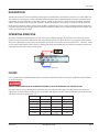
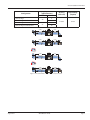
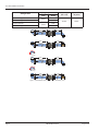
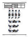
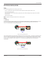
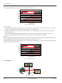
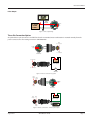
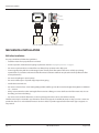
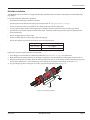
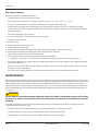
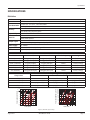
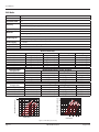
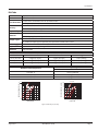
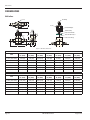
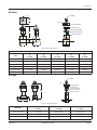
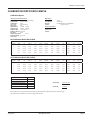
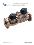
Vortex Shedding Flow Meter
RVL Series
VRX-UM-00371-EN-02 (August 2015)
User Manual
Vortex Shedding Flow Meter, RVL Series
Page ii
VRX-UM-00371-EN-02
August 2015
User Manual
CONTENTS
Description . . . . . . . . . . . . . . . . . . . . . . . . . . . . . . . . . . . . . . . . . . . . . . . . . . . . . . . . . . . . . . . . . . . . . . . . . .5
Operating Principle . . . . . . . . . . . . . . . . . . . . . . . . . . . . . . . . . . . . . . . . . . . . . . . . . . . . . . . . . . . . . . . . . . . . .5
Fluids . . . . . . . . . . . . . . . . . . . . . . . . . . . . . . . . . . . . . . . . . . . . . . . . . . . . . . . . . . . . . . . . . . . . . . . . . . . . . .5
General Installation Information . . . . . . . . . . . . . . . . . . . . . . . . . . . . . . . . . . . . . . . . . . . . . . . . . . . . . . . . . . . . .6
Flow Rate and Range Requirements . . . . . . . . . . . . . . . . . . . . . . . . . . . . . . . . . . . . . . . . . . . . . . . . . . . . . . . 6
Piping Requirements . . . . . . . . . . . . . . . . . . . . . . . . . . . . . . . . . . . . . . . . . . . . . . . . . . . . . . . . . . . . . . . . .6
Back Pressure . . . . . . . . . . . . . . . . . . . . . . . . . . . . . . . . . . . . . . . . . . . . . . . . . . . . . . . . . . . . . . . . . . . . . 10
Outputs . . . . . . . . . . . . . . . . . . . . . . . . . . . . . . . . . . . . . . . . . . . . . . . . . . . . . . . . . . . . . . . . . . . . . . . . 10
K-Factors . . . . . . . . . . . . . . . . . . . . . . . . . . . . . . . . . . . . . . . . . . . . . . . . . . . . . . . . . . . . . . . . . . . . . . . . 10
Electrical Installation . . . . . . . . . . . . . . . . . . . . . . . . . . . . . . . . . . . . . . . . . . . . . . . . . . . . . . . . . . . . . . . . . . . 11
Power . . . . . . . . . . . . . . . . . . . . . . . . . . . . . . . . . . . . . . . . . . . . . . . . . . . . . . . . . . . . . . . . . . . . . . . . . . 11
Wiring . . . . . . . . . . . . . . . . . . . . . . . . . . . . . . . . . . . . . . . . . . . . . . . . . . . . . . . . . . . . . . . . . . . . . . . . . 11
Three-Pin Connection Option . . . . . . . . . . . . . . . . . . . . . . . . . . . . . . . . . . . . . . . . . . . . . . . . . . . . . . . . . . 13
Mechanical Installation . . . . . . . . . . . . . . . . . . . . . . . . . . . . . . . . . . . . . . . . . . . . . . . . . . . . . . . . . . . . . . . . . 14
RVL Inline Installation . . . . . . . . . . . . . . . . . . . . . . . . . . . . . . . . . . . . . . . . . . . . . . . . . . . . . . . . . . . . . . . 14
RVL Wafer Installation . . . . . . . . . . . . . . . . . . . . . . . . . . . . . . . . . . . . . . . . . . . . . . . . . . . . . . . . . . . . . . . 15
RVL Tube Installation . . . . . . . . . . . . . . . . . . . . . . . . . . . . . . . . . . . . . . . . . . . . . . . . . . . . . . . . . . . . . . . . 16
Maintenance . . . . . . . . . . . . . . . . . . . . . . . . . . . . . . . . . . . . . . . . . . . . . . . . . . . . . . . . . . . . . . . . . . . . . . . . 16
Specifications . . . . . . . . . . . . . . . . . . . . . . . . . . . . . . . . . . . . . . . . . . . . . . . . . . . . . . . . . . . . . . . . . . . . . . . 17
RVL Inline . . . . . . . . . . . . . . . . . . . . . . . . . . . . . . . . . . . . . . . . . . . . . . . . . . . . . . . . . . . . . . . . . . . . . . . 17
RVL Wafer . . . . . . . . . . . . . . . . . . . . . . . . . . . . . . . . . . . . . . . . . . . . . . . . . . . . . . . . . . . . . . . . . . . . . . . 18
RVL Tube . . . . . . . . . . . . . . . . . . . . . . . . . . . . . . . . . . . . . . . . . . . . . . . . . . . . . . . . . . . . . . . . . . . . . . . . 19
Dimensions . . . . . . . . . . . . . . . . . . . . . . . . . . . . . . . . . . . . . . . . . . . . . . . . . . . . . . . . . . . . . . . . . . . . . . . . . 20
RVL Inline . . . . . . . . . . . . . . . . . . . . . . . . . . . . . . . . . . . . . . . . . . . . . . . . . . . . . . . . . . . . . . . . . . . . . . . 20
RVL Wafer . . . . . . . . . . . . . . . . . . . . . . . . . . . . . . . . . . . . . . . . . . . . . . . . . . . . . . . . . . . . . . . . . . . . . . . 21
RVL Tube . . . . . . . . . . . . . . . . . . . . . . . . . . . . . . . . . . . . . . . . . . . . . . . . . . . . . . . . . . . . . . . . . . . . . . . . 21
Troubleshooting . . . . . . . . . . . . . . . . . . . . . . . . . . . . . . . . . . . . . . . . . . . . . . . . . . . . . . . . . . . . . . . . . . . . . . 22
Current Loop . . . . . . . . . . . . . . . . . . . . . . . . . . . . . . . . . . . . . . . . . . . . . . . . . . . . . . . . . . . . . . . . . . . . . 22
Over-Stressed Sensor . . . . . . . . . . . . . . . . . . . . . . . . . . . . . . . . . . . . . . . . . . . . . . . . . . . . . . . . . . . . . . . . 22
Calibration Certificate Sample . . . . . . . . . . . . . . . . . . . . . . . . . . . . . . . . . . . . . . . . . . . . . . . . . . . . . . . . . . . . . 23
August 2015
VRX-UM-00371-EN-02
Page iii
Vortex Shedding Flow Meter, RVL Series
Page iv
VRX-UM-00371-EN-02
August 2015
Description
DESCRIPTION
The RVL series meter uses vortex-shedding technology for repeatable flow measurement accurate to ±1 percent of full scale.
The meter has no moving parts, and any potential for fluid contamination is eliminated by the corrosion-resistant all plastic
construction. The meter includes a compact two-wire (4…20 mA) or three-wire (0…5V DC or pulse) transmitter, contained
within a conveniently replaceable plug-in electronics module. All electronics are housed in a corrosion-resistant enclosure.
Unlike meters containing metal or moving parts, the RVL is perfect for aggressive or easily contaminated fluids. Applications
range from ultra-pure water to highly corrosive chemicals and slurries. Units can be re-calibrated and the meter output span
can be reprogrammed in the field.
OPERATING PRINCIPLE
Operation of the RVL vortex flow meter is based on the vortex shedding principle. As fluid moves around a body, vortices
(eddies) are formed and move downstream. They form alternately, from one side to the other, causing pressure fluctuations.
The pressure fluctuations are sensed by a piezoelectric crystal in the sensor tube, and are converted to a 4…20 mA, 0…5V DC
or pulse signal. The frequency of the vortices is directly proportional to the flow rate. The results are extremely accurate and
repeatable measurements using no moving parts.
Counter
Detector
Bluff
Body
Detector
Figure 1: Operating principle
FLUIDS
Use any clean liquid compatible with the plastic material of construction that does not contain significant amounts of fibers
or abrasive materials.
DO NOT USE WITH EXPLOSIVE OR FLAMMABLE MATERIALS, FOOD OR BEVERAGES, OR GASEOUS FLUIDS.
Viscosities above 1 cSt raise the minimum usable flow rate and reduce the flow range. This effect is linear to viscosity. No
adjustments are required for viscosities up to 2.0 cSt. Liquids with higher viscosities adversely affect the permissible amount
and duration of over range flow. See Table 1.
Viscosity
Minimum
Maximum
Flow Range
1 cSt
1
12
12:1
2 cSt
2
12
6:1
3 cSt
3
12
4:1
4 cSt
4
12
3:1
5 cSt
5
12
2.4:1
6
12
2:1
6 cSt
Table 1: Viscosity and flow range
August 2015
VRX-UM-00371-EN-02
Page 5
General Installation Information
GENERAL INSTALLATION INFORMATION
Before installing the meter:
• Find an area for installation away from large electrical motors, transformers or other devices that can produce high
electromagnetic or electrostatic fields. The vortex transmitter contains electric circuitry that can be affected by
these interferences.
• Proper grounding is required to eliminate electrical noise which may be present within the fluid and piping system or in
the near vicinity of the vortex transmitter. Use exterior grounding strap for non-conductive piping systems to provide a
path to earth ground. Properly ground pipes in conductive piping systems.
Flow Rate and Range Requirements
Most manufacturers state flow range capabilities by publishing the maximum allowed flow rates. Then they provide a
turndown ratio to determine minimum flow rate. To use the turndown ratio, simply divide the maximum rate by the ratio
to determine the minimum rate. Vortex flow meters have a 12:1 turndown ratio at a viscosity of 1 cSt. Higher viscosities will
reduce the turndown.
NNOTE: The 1/4 in. NPT and 1/2 in. flare end meters have a standard turndown ratio of 8:1.
Piping Requirements
Turbulence in the pipeline can affect the accuracy of flow meters. Typical sources of turbulence are pumps, valves, change
in pipe diameter or changes-in-direction in the line. Install the meter away from the turbulence source to avoid turbulence
issues. These distances are indicated in Pipe Diameters (PD). For example, 10 PD is ten times the inside pipe diameter away
from the source of turbulence. Follow upstream and downstream distances for all sources of turbulence. See Figure 2 on page
7, Figure 3 on page 8, Figure 4 on page 9 and Figure 5 on page 9 for proper piping distance requirements.
NNOTE: Pulsating flow affects accuracy. Pressure pulses affect accuracy.
Page 6
VRX-UM-00371-EN-02
August 2015
General Installation Information
Piping Requirements
(pipe diameters)
Configuration
Inlet
1 plane change
Outlet
20
1 plane change w/outlet valve
2 plane changes
27
2 plane changes w/outlet valve
20 Dia
Minimum
Accuracy
(full scale)
Repeatability
(of point)
±1.00%
0.25%
5
10
5
10
5 Dia
Minimum
Flow
20 Dia
Minimum
10 Dia
Minimum
Flow
Two Plane
Changes
27 Dia
Minimum
5 Dia
Minimum
Flow
Two Plane
Changes
27 Dia
Minimum
10 Dia
Minimum
Flow
Figure 2: Horizontal flow with sensing element in vertical orientation
August 2015
VRX-UM-00371-EN-02
Page 7
General Installation Information
Piping Requirements
Configuration
Inlet
1 plane change
1 plane change w/outlet valve
2 plane changes
2 plane changes w/outlet valve
20 PD
27 PD
20 Dia
Minimum
Outlet
Accuracy
(full scale)
Repeatability
(of point)
±1.50%
0.25%
5 PD
10 PD
5 PD
10 PD
5 Dia
Minimum
Flow
20 Dia
Minimum
10 Dia
Minimum
Flow
Two Plane
Changes
27 Dia
Minimum
5 Dia
Minimum
Flow
Two Plane
Changes
27 Dia
Minimum
10 Dia
Minimum
Flow
Figure 3: Horizontal flow with sensing element in horizontal position
Page 8
VRX-UM-00371-EN-02
August 2015
General Installation Information
Piping Requirements
Configuration
Inlet
1 plane change
20 PD
1 plane change w/outlet valve
2 plane changes
27 PD
2 plane changes w/outlet valve
Outlet
Accuracy
(full scale)
Repeatability
(of point)
±1.00%
0.25%
5 PD
10 PD
5 PD
10 PD
Two Plane
Changes
Two Plane
Changes
5 Dia
Minimum
10 Dia
Minimum
20 Dia
Minimum
Flow
27 Dia
Minimum
Flow
Flow
Flow
27 Dia
Minimum
10 Dia
Minimum
20 Dia
Minimum
5 Dia
Minimum
Figure 4: Vertical flow with a change in direction or valve
25 Dia
Minimum
10 Dia
Minimum
Flow
5 Dia
Minimum
20 Dia
Minimum
2 Dia
Minimum
5 Dia
Minimum
25 Dia
Minimum
Flow
5 Dia
Minimum
20 Dia
Minimum
Two Plane
Changes
2 Dia
Minimum
5 Dia
Minimum
30 Dia
Minimum
Flow
5 Dia
Minimum
25 Dia
Minimum
2 Dia
Minimum
Figure 5: Horizontal flow with a change in pipe diameter
August 2015
VRX-UM-00371-EN-02
Page 9
General Installation Information
Back Pressure
Back pressure, the pressure immediately downstream of the meter, must be maintained above a minimum level to avoid
cavitation. For most applications this may be ignored if the flow rate is less than 75% of maximum. For other applications, use
the following formula to calculate the minimum back pressure.
Back Pressure = 2.75 ∆P + 1.25 PV - 14.7
Where:
∆P = Pressure drop in psi at max flow
PV = Vapor pressure in psia of the liquid at operating temp.
(For example, the PV of water at 100° F is 0.42.)
BP = Back pressure (downstream of meter) in psig.
Example
For water, at 100° F (37° C) in a 1/2 in. (12.7 mm) meter, where the maximum pressure drop is 8 psi minimum back pressure is
7.8 psig.
BP = (2.75 × 8) + (1.25 × 0.42) - 14.7
BP = 22 + 0.525 - 14.7
BP = 7.825
Outputs
The RVL series meters can be ordered with either an analog output (voltage or current) or a rate frequency output. The
standard analog output is a 4…20 mA current, an optional 0…5V DC is also available. The analog output can be re-scaled in
the field using a PC communications cable and programming software, which are both available as P.N. RVS220-954.
NNOTE: All three outputs use unique circuit boards and cannot be changed in the field.
The rate frequency output produces pulses whose frequency is proportional to the flow going through the meter. Each meter
has a slightly different output frequency which is listed on the calibration sheet that accompanies the meter. See Table 2 for
the long term average full scale output frequency for standard size meters.
Meter Size
Average Full Scale Frequency
Pulse Width
1/4 in. (6.35 mm)
1055 Hz
0.47 msec
1/2 in. (12.7 mm)
820 Hz
0.61 msec
1/2 in. (12.7 mm)
570 Hz
0.88 msec
3/4 in. (19.05 mm)
284 Hz
1.76 msec
1 in. (25.4 mm)
292 Hz
1.71 msec
1-1/2 in. (38.1 mm)
144 Hz
3.47 msec
2 in. (50.8 mm)
148 Hz
3.38 msec
61 Hz
8.20 msec
3 in. (76.2 mm)
Table 2: Full scale output frequency
The frequency output option generates a square wave with an amplitude that matches the input power level. The pulse width
varies with frequency and is found by using the following formula.
PW in sec. =
1
2 x Ma ximum Frequency (H z)
K-Factors
The K-factor is the number of pulses that must be accumulated to equal a particular volume of fluid. Think of each pulse as
representing a small fraction of the totalizing unit.
Calibration reports that accompany RVL series meters include a nominal K-factor in both gallons and liters. See “Calibration
Certificate Sample” on page 23.
Page 10
VRX-UM-00371-EN-02
August 2015
Electrical Installation
ELECTRICAL INSTALLATION
Power
Use the following guidelines when selecting a power source:
• Use an 8…28V DC power supply. The specific connection depends on which output is option is used.
• Use clean electrical line power.
• Do not operate this unit on circuits with noisy components such as fluorescent lights, relays, compressors or variable
frequency drives.
• Use linear power supplies.
NNOTE: The power and output connections share a common ground.
Wiring
4…20 mA Loop
Connect a twisted pair wire (not provided) to the terminals of the transmitter marked 8…28V DC and Output. Do not connect
the shield to the transmitter if the twisted pair wire is shielded. The shield should be grounded at the receiver only.
See Figure 6. The transmitter is reverse-polarity protected.
8…28V DC
+8-28 VDC
Output
Output
Gnd
4…20 mA
Programming
POWER
SUPPLY
8…28V DC
RECEIVER
Load
Figure 6: Loop connection with single load
The receiving equipment must accept industry standard true two-wire or loop powered 4…20 mA process transmitter inputs.
The power can either be supplied by the receiving equipment or an external power supply that supplies 24V DC an 30 mA.
See Figure 6 for the wiring setup using an external power source and Figure 7 using the receiver as the power source. Several
receivers may be connected in a series as shown in Figure 7, but only one should provide power, and all should have
isolated inputs.
8…28V DC
+8-28 VDC
Output
Output
Gnd
4...20 mA
RECEIVER/POWER SUPPLY
Programming
RECEIVER
RECEIVER
Additional Loads
Figure 7: Loop connection with multiple loads
August 2015
VRX-UM-00371-EN-02
Page 11
Electrical Installation
The voltage provided by the receiver must be within the limits shown in Figure 8.
1100
1000
Supply Voltage – 8V DC
Loop Load (Ohm's)
900
0.02
= Maximum Loop Resistance
800
700
600
500
400
Operate in the
Shaded Region
300
200
100
10
8
12
14
16
18
20
22
24
26
28
Supply Voltage (V DC)
Figure 8: Supply voltage chart
To use this figure:
1. Add the resistance of all the receivers, indicators and the wire in the loop. If the wire resistance is unknown, use a value of
50 ohm for a twisted wire of 1000 feet or less with a gauge of #22 awg or heavier.
2. Find the total load (in ohms) on the left side of the chart in Figure 8 and follow that value horizontally until it intersects
with the shaded area.
3. From the intersection point look straight down to where a vertical line would intersect the voltage scale. This is the
minimum voltage needed for the transmitter to operate properly under the specific load conditions.
Example
After checking the specification for all the loads in an application the total amounted to 800 ohms. Following the 800 ohm
line to the right, the intersection point is about 3/4 of the way across the chart in Figure 9.
A vertical line through the intersection point crosses the voltage axis at about 24V DC, so with a load of 800 ohms a standard
24 volt power supply would be used.
1100
1000
Supply Voltage - 8V DC
= Maximum Loop Resistance
0.02
Loop Load (Ohm's)
900
800
700
600
500
400
Operate in the
Shaded Region
300
200
100
8
10
12
14
16
18
20
22
24
26
28
Supply Voltage (V DC)
Figure 9: Supply voltage example
0…5V DC Output
Digital Display
0…5V DC
8…28V DC
8…28V DC
POWER
SUPPLY
+8-28 VDC
Output
Output
Ground
Gnd
Programming
Figure 10: 0…5V DC wiring
Page 12
VRX-UM-00371-EN-02
August 2015
Electrical Installation
Pulse Output
Counter
Pulse
Output
8…28V DC
POWER
SUPPLY
8…28V DC
Output
Ground
+8-28 VDC
Output
Gnd
Programming
Figure 11: Pulse output wiring
Three-Pin Connection Option
An optional three-pin connection is available for when the transmitter/meter combination is mounted remotely from the
power source/receiver. The mating connector is P.N. RF8687000.
White
4…20 mA Input
8…28V DC
Output
+8-28 VDC
Output
Gnd
Black
– 4…20 mA Input
Meter
Electronics
+
4…20 mA Input
-
8…28V DC
Power Supply
P.N. RF8687000 Connector
– 4…20 mA Input
mA
+
-
Ammeter
Figure 12: Remote connection loop power
Black
- Supply Green
Ground
+8-28 VDC
Output
Gnd
White
Output
Meter
Electronics
+
Green
Ground
8…28V DC
Output
Ground
Black
+V
-
8…28V DC
Power Supply
P.N. RF8687000 Connector
White
Output
Counter
Figure 13: Remote connection 0…5V DC or pulse output
August 2015
VRX-UM-00371-EN-02
Page 13
Mechanical Installation
ON
1
2
3
4
5
6
7
White
4…20 mA Input
8
1
2
3
CW
SPAN
Black
– 4…20 mA Input
ZERO
Figure 14: Integral configuration for rate/totalizer indicator
MECHANICAL INSTALLATION
RVL Inline Installation
For proper installation, follow these guidelines:
• Install the meter where pipe vibration is minimal.
• Use the upstream and downstream piping requirements shown in “Piping Requirements” on page 6.
• Do not use upstream valves to control flow rate. Always keep upstream valves fully open.
• Connect good quality ball valves with integral unions directly to the flow meter if the valves are fully open during
operation for easy isolation and removal of the flow meter. Cavitation and flow rate pulsation adversely affects the flow
meter performance.
• Do not use diaphragm or piston pumps.
• Do not use Teflon tape or any kind of pipe dope when piping.
• Handle the meter with care.
• Do not use excessive force. Screw mating fittings (FNPT) and flanges into the meter hand-tight; then tighten an additional
1/2…3/4 turn.
• Always use two wrenches when turning the flow meter into a fitting; one across the flats on the flow meter end, close to
the fitting, and one on the fitting.
• Do not use tools inside the flow meter, as this may damage the vortex sensor, and void the warranty.
The flow meter may be mounted in any orientation. Three holes, tapped 1/4-20 UNC-2B, 0.375 in.-deep, on 3/4 in. centers are
provided on the 3/4 in. and smaller flow meters. Use these holes to provide support for the flow meter if pipe supports are
not practical.
Page 14
VRX-UM-00371-EN-02
August 2015
Mechanical Installation
RVL Wafer Installation
The RVL Wafer series transmitters are designed with wafer style flow bodies, that mount easily between standard ANSI style
pipe flanges.
For proper installation, follow these guidelines:
• Install the meter where pipe vibration is minimal.
• Use the upstream and downstream piping requirements shown in “Piping Requirements” on page 6.
• Do not use upstream valves to control flow rate. Always keep upstream valves fully open.
• Connect good quality ball valves with integral unions directly to the flow meter if the valves are fully open during
operation for easy isolation and removal of the flow meter. Cavitation and flow rate pulsation adversely affects the flow
meter performance.
• Do not use diaphragm or piston pumps.
• Do not use Teflon tape or any kind of pipe dope when piping.
• Do not allow gaskets to protrude into the flow stream on flanged meters.
Flange Size
Recommended Torque
1/2…1-1/2 in.
10…15 ft Ibs
2…3 in.
20…30 ft Ibs
Table 3: Torque rating
Follow these steps for proper installation and operation:
1. Space flanges to accommodate the width of the flow body. See “RVL Wafer” on page 21 for dimensions.
2. Align the flow body centered with respect to flanges and gaskets, insert threaded rods, retaining nuts and lock washers.
3. Install all retaining nuts hand-tight, and then uniformly tighten the nuts in an alternating sequence, diametrically opposed
to each other. Uniform stress across the flange prevents leakage at the gasket. Torque ratings are listed in Table 3.
4. Use grounding rings when metal pipes are used in conjunction with this meter. See Figure 15.
Grounding
Rings
Figure 15: Grounding ring installation
August 2015
VRX-UM-00371-EN-02
Page 15
Maintenance
RVL Tube Installation
For proper installation, follow these guidelines:
• Install the meter where pipe vibration is minimal.
• Use the upstream and downstream piping requirements shown in “Piping Requirements” on page 6.
• Do not use upstream valves to control flow rate. Always keep upstream valves fully open.
• Connect good quality ball valves with integral unions directly to the flow meter if the valves are fully open during
operation for easy isolation and removal of the flow meter. Cavitation and flow rate pulsation adversely affects the flow
meter performance.
• Do not use diaphragm or piston pumps.
• Do not use Teflon tape or any kind of pipe dope when piping.
• Handle the meter with care.
To install the meter:
1. Remove any burrs from the pipe ends.
2. Slide the flare nut onto the pipe.
3. Push the flare nut back far enough so that it will be out of the way when you use the flaring tool.
4. Clip the pipe in the flaring tool, keeping the end flush with the face of the tool.
5. Slowly turn the handle on the tool until it bottoms out.
6. Unscrew the handle and remove the tool to check the quality of the flare.
a. If the flare is not smooth or even the first time, cut off the end with your pipe cutter, and repeat steps 4…6.
7. Line up and tighten the nut and flared pipe to the fitting body. Make the connection tight, but not so tight that the flow
meter body is distorted.
• Always use two wrenches when turning a fitting onto the flow meter; one across the flats on the flow meter end close to
the fitting, and one on the fitting.
• Do not use tools inside the flow meter, as this may damage the vortex sensor, and invalidate the warranty.
MAINTENANCE
RVL flow meters do not require maintenance in normal service if they are properly installed. Remove the meter from service
for cleaning if the flow tube becomes clogged with debris. Significant clogging often results in high (up to 20%) and/or erratic
output. Do not stick tools into the tube, as this may permanently damage the vortex sensor. The vortex sensor cannot be
repaired in the field. To clean the flow tube, run hot, up to 160° F (71.1° C), soapy water into the downstream end of the flow
tube. Dislodge large objects jammed against the bluff body by lightly tapping the upstream end of the flow tube against a
firm surface.
CAUTION
DO NOT REMOVE VORTEX METER DURING OPERATION. ALWAYS DISCONNECT THE PRIMARY POWER SOURCE BEFORE
INSPECTION OF SERVICE. DO NOT TAP THE FLOW TUBE SO HARD THAT THE THREADS, ON THREADED UNITS, BECOME
DAMAGED
A schedule of maintenance checks should be determined based upon environmental conditions and frequency of use.
Inspect the meter at least once a year.
• Visually check for evidence of overheating by noting discoloration of wires or other components.
• Check for damaged or worn parts, especially the bluff body, or indications of corrosion.
• Check for tight, clean electrical connections and that the device is operating properly.
Page 16
VRX-UM-00371-EN-02
August 2015
Specifications
SPECIFICATIONS
RVL Inline
Fluid
Liquids
Connection
NPT Female or Butt (PVDF only)
12:1 for 1/2…2 in. (12.7…50.8 mm) meters
Turndown Ratio
8:1 for 1/4 in. (6.35 mm) meter
±1% of full scale (4…20 mA or 0…5V DC)
Accuracy
±2% of full scale, frequency pulse
Repeatability
±0.25% of actual flow
PVC standard
Materials
CPVC, PVDF optional
4…20 mA standard
Output Signals
0…5V DC or frequency pulse optional push-pull driver 150 mA sink or source
Power Supply
8…28V DC
Response Time
2 seconds minimum, step-change-in flow
Enclosure
Type 4X (IP 66)
Nominal Flow Rates
Tube Size
Minimum Flow
Maximum Flow
Full Scale Frequency
Weight
1/4 in. (6.35 mm)
0.6 gpm (2.3 lpm)
5 gpm (18.9 lpm)
1052 Hz
1.5 lbs (0.68 kg)
1/2 in. (12.7 mm)
1.3 gpm (4.7 lpm)
15 gpm (56.8 lpm)
570 Hz
1.6 lbs (0.72 kg)
3/4 in. (19.05 mm)
2.1 gpm (7.9 lpm)
25 gpm (94.6 lpm)
284 Hz
1.7 lbs (0.77 kg)
1 in. (25.4 mm)
4.2 gpm (15.8 lpm)
50 gpm (189.3 lpm)
292 Hz
1.8 lbs (0.80 kg)
1-1/2 in. (38.1 mm)
8.3 gpm (31.5 lpm)
100 gpm (378.5 lpm)
144 Hz
3.1 lbs (1.40 kg)
2 in. (50.8 mm)
16.7 gpm (63.1 lpm)
200 gpm (757.1 lpm)
142 Hz
2.7 lbs (1.22 kg)
Maximum Operating Pressure psig (KPa)
PVC
CPVC
PVDF
203° F (95° C)
Not recommended
Consult factory
Consult factory
150° F (66° C)
Not recommended
63 psig (434 KPa)
130 psig (896 KPa)
100° F (38° C)
93 psig (641 KPa)
120 psig (827 KPa)
150 psig (1034 KPa)
70° F (21° C)
150 psig (1034 KPa)
150 psig (1034 KPa)
150 psig (1034 KPa)
.5
.2
.1
.05
.3
.5 1
2
5 10 15 25 50 100 200
1 in
.
n.
200
100
50
35
20
10
5
3.5
2
5
10 20
50
30
FLOW (GPM)
1½
i
2 in n.
.
½
in.
¾i
n.
1½
i
2 in n.
.
in.
½
¾i
1
n.
2
1000
750
500
350
¼i
.
1 in
n.
¼i
PRESSURE DROP (PSID)
20
12 10
8
5
PRESSURE DROP (MILLIBAR)
Maximum Fluid
Temperature
100
200 600
300 800
FLOW (LPM)
Figure 16: RVL inline pressure drop
August 2015
VRX-UM-00371-EN-02
Page 17
Specifications
RVL Wafer
Fluid
Liquids
Connection
Wafer
Turndown Ratio
12:1
±1% of full scale (4…20 mA or 0…5V DC)
Accuracy
±2% of full scale, frequency pulse
Repeatability
±0.25% of actual flow
PVC standard
Materials
CPVC, Polypropylene, PVDF optional
4…20 mA standard
Output Signals
0…5V DC or frequency pulse optional push-pull driver 150 mA sink or source
Power Supply
8…28V DC
Response Time
2 seconds minimum, step-change-in flow
Enclosure
Type 4X (IP 66)
Nominal Flow Rates
Minimum Flow
Maximum Flow
Full Scale Frequency
1.3 gpm (4.7 lpm)
15 gpm (56.8 lpm)
570 Hz
2.1 gpm (7.9 lpm)
25 gpm (94.6 lpm)
284 Hz
4.2 gpm (15.8 lpm)
50 gpm (189.3 lpm)
292 Hz
8.3 gpm (31.5 lpm)
100 gpm (378.5 lpm)
144 Hz
16.7 gpm (63.1 lpm)
200 gpm (757.1 lpm)
148 Hz
25.0 gpm (94.6 lpm)
300 gpm (1136 lpm)
61 Hz
Tube Size
1/2 in. (12.7 mm)
3/4 in.(19.05 mm)
1 in. (25.4 mm)
1-1/2 in. (38.1 mm)
2 in. (50.8 mm)
3 in. (76.2 mm)
Weight
0.8 lbs (0.36 kg)
0.9 lbs (0.41 kg)
1.1 lbs (0.50 kg)
1.7 lbs (0.77 kg)
2.6 lbs (1.17 kg)
4.8 lbs (2.16 kg)
PVDF
Consult factory
130 psig (896 KPa)
150 psig (1034 KPa)
150 psig (1034 KPa)
Maximum Fluid
Temperature
203° F (95° C)
150° F (66° C)
100° F (38° C)
70° F (21° C)
PVC
Not recommended
Consult factory
Consult factory
Consult factory
Maximum Operating Pressure, High Pressure
CPVC
Polypropylene
Not recommended
Not recommended
Consult factory
90 psig (621 KPa)
Consult factory
130 psig (896 KPa)
Consult factory
150 psig (1034 KPa)
PVDF
Consult factory
300 psig (2068 KPa)
400 psig (2750 KPa)
400 psig (2750 KPa)
.5
.2
.1
.05
.3
.5 1
2
100
5 10 15 25 50 100 200 300
50
35
20
10
5
3.5
2
5
10 20
50
30
FLOW (GPM)
3 in
200
1½
in.
1 in 3/4 in
.
.
.
2 in
3 in
.
1
1000
750
500
350
1/2
.
1 in
in.
1½
n.
¾i
in.
2
½
PRESSURE DROP (PSID)
20
12 10
8
5
.
Maximum Operating Pressure, Standard
CPVC
Polypropylene
Consult factory
Not recommended
63 psig (434 KPa)
90 psig (621 KPa)
120 psig (827 KPa)
130 psig (896 KPa)
150 psig (1034 KPa)
150 psig (1034 KPa)
in.
2 in
.
PVC
Not recommended
Not recommended
100 psig (690 KPa)
150 psig (1034 KPa)
PRESSURE DROP (MILLIBAR)
Maximum Fluid
Temperature
203° F (95° C)
150° F (66° C)
100° F (38° C)
70° F (21° C)
100
200 600 1200
300 800
FLOW (LPM)
Figure 17: RVL wafer pressure drop
Page 18
VRX-UM-00371-EN-02
August 2015
Specifications
RVL Tube
Fluid
Liquids
Connection
Tube (Flare end)
12:1 for 3/4 in. (19.05 mm) and 1 in. (25.4 mm) meters
Turndown Ratio
8:1 for 1/2 in. (12.7 mm) meter
±1% of full scale (4…20 mA or 0…5V DC)
Accuracy
±2% of full scale, frequency pulse
Repeatability
±0.25% of actual flow
PVC standard
Materials
CPVC, Polypropylene, PVDF optional
4…20 mA standard
Output Signals
0…5V DC or frequency pulse optional push-pull driver 150 mA sink or source
Power Supply
8…28V DC
Response Time
2 seconds minimum, step-change-in flow.
Enclosure
Type 4X (IP 66)
Nominal Flow Rates
Tube Size
Minimum Flow
Maximum Flow
Weight
1/2 in. (12.7 mm)
0.6 gpm (2.3 lpm)
5 gpm (18.9 lpm)
1.5 lbs (0.68 kg)
3/4 in. (19.05 mm)
1.3 gpm (4.7 lpm)
15 gpm (56.8 lpm)
1.6 lbs (0.72 kg)
1 in. (25.4 mm)
2.1 gpm (7.9 lpm)
25 gpm (94.6 lpm)
1.7 lbs (0.77 kg)
Maximum Operating Pressure
Maximum Fluid Temperature
150° F(66° C)
130 psig (896 KPa)
100° F (38° C)
150 psig (1034 KPa)
70° F (21° C)
150 psig (1034 KPa)
1
.5
.2
.1
.05
.3
.5 1
2
5 10 15 25 50 100 200
n.
200
1 in
.
½i
n.
1000
750
500
350
¾i
¾
in.
2
1 in
.
½i
n.
PRESSURE DROP (MILLIBAR)
FLOW (LPM)
20
12 10
8
5
PRESSURE DROP (PSID)
PVDF
100
50
35
20
10
5
3.5
2
5
10 20
50
30
100
200 600
300 800
FLOW (LPM)
FLOW (GPM)
Figure 18: RVL tube pressure drop
August 2015
VRX-UM-00371-EN-02
Page 19
Dimensions
DIMENSIONS
RVL Inline
Cord Grip
Cord Grip
F
Cover
Conduit Adapter
Terminal Strip
Electronics Module
I
NPT/BUTT
END
Three-Pin Connector
A
Flow Sensor Body
B
E
D
C
Figure 19: RVL inline dimensions
PVC/CPVC
Size
A
in. (mm)
B
in. (mm)
C
in. (mm)
D
in. (mm)
E
in. (mm)
F
in. (mm)
I
in. (mm)
1/4 in. (6.35 mm)
3.81 (97)
1.75 (45)
5.25 (133)
2.50 (64)
0.30 (8)
2.88 (73)
3.00 (76)
1/2 in. (12.7 mm)
3.81 (97)
1.75 (45)
7.13 (181)
2.50 (64)
0.55 (14)
2.88 (73)
3.00 (76)
3/4 in. (19.05 mm)
3.81 (97)
1.75 (45)
7.63 (194)
2.50 (64)
0.74 (19)
2.88 (73)
3.00 (76)
1 in. (25.4 mm)
3.92 (100)
1.75 (45)
8.03 (204)
2.50 (64)
0.96 (24)
2.88 (73)
3.00 (76)
1-1/2 in. (38.1 mm)
3.90 (99)
2.00 (51)
8.37 (213)
2.50 (64)
1.50 (38)
2.88 (73)
3.38 (86)
2 in. (50.8 mm)
4.31 (109)
2.00 (51)
8.37 (213)
2.50 (64)
1.94 (49)
2.88 (73)
3.38 (86)
E
in. (mm)
F
in. (mm)
I
in. (mm)
PVDF (BUTT Fusion Only)
Size
A
in. (mm)
B
in. (mm)
C
in. (mm)
D
in. (mm)
1/4 in. (6.35 mm)
5.90 (150)
0.63 (16)
4.87 (124)
1.31 (33)
0.30 (8)
2.88 (73)
3.00 (76)
1/2 in. (12.7 mm)
5.75 (146)
0.78 (20)
4.87 (124)
1.31 (33)
0.55 (14)
2.88 (73)
3.00 (76)
3/4 in. (19.05 mm)
5.75 (146)
0.94 (24)
4.87 (124)
1.44 (37)
0.74 (19)
2.88 (73)
3.00 (76)
1 in. (25.4 mm)
5.88 (149)
1.19 (30)
5.09 (129)
2.00 (51)
0.96 (24)
2.88 (73)
3.00 (76)
1-1/2 in. (38.1 mm)
6.21 (158)
1.50 (38)
6.24 (158)
2.50 (64)
1.50 (38)
2.88 (73)
3.38 (86)
2 in. (50.8 mm)
6.60 (168)
1.88 (48)
6.77 (172)
3.00 (76)
1.94 (49)
2.88 (73)
3.38 (86)
Page 20
VRX-UM-00371-EN-02
August 2015
Dimensions
RVL Wafer
Cord Grip
Cord Grip
E
Cover
Conduit Adapter
Terminal Strip
Electronics Module
Three-Pin Connector
A
Flow Sensor Body
B
C
D
Figure 20: RVL wafer dimensions
RVL (Wafer) Dimensions PP/PVC/CPVC/PVDF
Size
A
in. (mm)
B
in. (mm)
C
in. (mm)
D
in. (mm)
E
in. (mm)
1/2 in. (12.7 mm)
5.85 (149)
0.78 (20)
2.03 (52)
1.75 (45)
2.88 (73)
3/4 in. (19.05 mm)
5.90(150)
0.94 (24)
2.03 (52)
1.75 (45)
2.88 (73)
1 in. (25.4 mm)
5.69 (145)
1.19 (30)
2.25 (57)
1.75 (45)
2.88 (73)
1-1/2 in. (38.1 mm)
6.00 (152)
1.50 (38)
2.63 (67)
1.75 (45)
2.88 (73)
2 in. (50.8 mm)
6.37 (162)
1.88 (48)
3.22 (82)
1.75 (45)
2.88 (73)
3 in. (76.2 mm)
6.88 (175)
2.50 (64)
4.25 (108)
1.75 (45)
2.88 (73)
RVL Tube
Cord Grip
Cover
B
C
Conduit Adapter
Terminal Strip
Electronics Module
Three-Pin Connector
Flow Sensor Body
A
Figure 21: RVL tube dimensions
Tube Size
A
in. (mm)
B)
in. (mm)
C
in. (mm)
1/2 in. (12.7 mm)
1.31 (33.3)
6.25 (158.8)
4.87 (123.7)
3/4 in. (19.05 mm)
1.31 (33.3)
6.25 (158.8)
4.66 (118.4)
1 in. (25.4 mm)
1.44 (36.6)
6.59 (167.4)
5.42 (137.7)
August 2015
VRX-UM-00371-EN-02
Page 21
Troubleshooting
TROUBLESHOOTING
If difficulty is encountered, locate the symptom most likely present and follow the appropriate instructions.
Current Loop
No Current Output
• Place a DC voltmeter across the two terminal block screws. With the electronics module powered there must be at least
8V DC present. If there is less than 8V DC, but more than 0V DC, check the power source for sufficient voltage to drive the
loop, as shown in Figure 8 on page 12.
◊ If there is 0V DC, present check for a broken wire or connector in the loop.
• Check for the proper polarity of the current loop connections.
• Make sure the receiving device is configured to provide source current to the electronics module.
Zero Flow Indication (4 mA in Loop)
• Check that the flow is greater than the minimum specified for the particular size flow meter in use.
◊ If the flow rate is too low, replace the flow meter with the proper size flow meter.
◊ If the flow rate is sufficient, partially remove the electronic module. Check that the three pin connector that connects
the electronics module to the flow transducers is positively connected. See Figure 22. Align and insert the connector on
to the bottom of the electronics module if it is disconnected.
Terminal Strip
Electronics Module
Three-Pin Connector
Flow Sensor Body
Figure 22: Electrical connection
Erratic Flow Indication
• Check that there is at least 8V DC present across the two terminal block screws.
• Check for material clogging the flow meter and in the upstream piping.
• Check for erosion of the bluff body by sighting down the meters bore. Erosion or damage to the bluff body causes erratic
readings and compromise accuracy. If the erosion continues, the flow meter will need to be periodically replaced.
• Check upstream piping distance. See “Piping Requirements” on page 6.
• Check for excessive pipe vibration. Normal amounts of pipe vibration are easily tolerated. The transmitter module contains
a highly effective active filter that rejects false signals caused by pipe vibration. This filter is most effective under flowing
conditions. If vibration is causing the meter to indicate flow when the flow is stopped it will most likely not cause error
under flowing conditions. The false flow indication may be ignored, or the pipe may be restrained by firm clamps.
• Check for electrical noise. Under some conditions there can be high common mode AC noise present between the fluid
and the power supply ground. The flow meter is designed to reject up to 50 volts of AC common mode noise without loss
of accuracy. If noise adjustment is used, accuracy is effected at low flow rates. Place a ground strap on the pipe on both
sides of the flow meter (the flow meter is made of non-conductive plastic) and connect them both to the one point where
the loop is grounded if metal piping is used. See “Wiring” on page 11. Use a grounding orifice if plastic piping is used. The
transmitter module contains a highly effective active filter that will reject false signals due to high common mode voltage.
This filter is most effective under flowing conditions. If a false indication of flow is encountered at zero flow, it will probably
not cause error under flowing conditions.
Over-Stressed Sensor
The sensor can be over-stressed if the maximum permitted flow rate of 125% of recommended capacity (100% of HT meters)
is exceeded.
Page 22
VRX-UM-00371-EN-02
August 2015
Calibration Certificate Sample
CALIBRATION CERTIFICATE SAMPLE
Calibration Report
Unit Under Test (UUT) Information:
Description:
3/4” In-Line NPT End Flow Meter
Model Number:
RVL075-N 1 VNN
Serial Number:
99999
Sensor Type:
Vortex Shedding
Output type:
0-5V
Minimum Flow:
2.1 GPM 7.9 LPM
Maximum Flow:
25 GPM 94.6 LPM
Calibration Date: October 24, 2007
Calibration Interval: 12 Months
Cal. Liquid:
Water
Ambient Temperature:
71.74 °F
Ambient Humidity: 31.39 %RH
Linear Points:
5
Master Meter:
Std uncertainty:±0.25%
Traceability No:30400/31801
Model No:
FT8-8N EXW-LEG-5/FT-16 NEXW-LEG-1
Serial No:806890/16011903
Customer Information:
Customer Name:
Customer No.:
Order No.:
UUT Calibration Data Table In GPM:
Flow
Standard
Actual
GPM
UUT
Hz
UUT
Temp °F
Visc.
cSt
UUT F/V
Hz/cSt
UUT K
CYC/GAL
(Hz*60)/NK
GPM
Linear
COEFF.
1
25.00
100.000
72.00
0.949
105.406
240.00
24.57
1
18.00
75.000
72.00
0.949
79.055
250.00
18.43
1
12.00
50.000
72.00
0.949
52.703
250.00
1
6.00
25.000
72.00
0.949
26.352
250.00
1
2.10
10.000
72.00
0.949
10.541
285.71
Nominal K (NK)
Raw Err
% FS
Calc.
0-5V
Meas.
0-5V
Output
Err % FS
1.0174
1.71
5.000
5.000
0.00
0.9767
-1.71
3.600
3.680
0.40
12.29
0.9767
-1.14
2.400
2.420
0.10
6.14
0.9767
-0.57
1.200
1.200
0.00
2.46
0.8547
-1.43
0.420
0.420
0.00
Raw Err
% FS
Calc.
0-5V
Meas.
0-5V
Output
Err % FS
244.186
UUT Calibration Data Table In LPM:
Flow
Standard
Actual
GPM
UUT
Hz
UUT
Temp °F
Visc.
cSt
UUT F/V
Hz/cSt
UUT K
CYC/GAL
(Hz*60)/NK
GPM
Linear
COEFF.
1
94.64
100.000
72.00
0.949
105.406
63.40
93.01
1.0174
1.71
5.000
5.000
0.00
1
68.14
75.000
72.00
0.949
79.055
66.04
69.76
0.9767
-1.71
3.600
3.680
0.40
1
45.42
50.000
72.00
0.949
52.703
66.04
46.51
0.9767
-1.14
2.400
2.420
0.10
1
22.71
25.000
72.00
0.949
26.352
66.04
23.25
0.9767
-0.57
1.200
1.200
0.00
1
7.95
10.000
72.00
0.949
10.541
75.48
9.30
0.8547
-1.43
0.420
0.420
0.00
Nominal K (NK) 64.507
Status:
PASS
Meter Accuracy (of FS):
± 0.4 %
Average Calib. Temperature :
72 F
Average Calib. Specific Gravity :
1
Average Calib. Viscosity :
0.95 cSt
Flow Direction :
Forward
Calibrated By:
Ramon Benedict
Certified By:
Larry Perez
Racine calibrations are performed using standards traceable to National Institute of Standards and Technology.
The equipment and calibration procedures complies with ISO 9001
August 2015
VRX-UM-00371-EN-02
Page 23
Vortex Shedding Flow Meter, RVL Series
Control. Manage. Optimize.
Trademarks appearing in this document are the property of their respective entities. Due to continuous research, product improvements and enhancements, Badger Meter reserves
the right to change product or system specifications without notice, except to the extent an outstanding contractual obligation exists. © 2015 Badger Meter, Inc. All rights reserved.
www.badgermeter.com
The Americas | Badger Meter | 4545 West Brown Deer Rd | PO Box 245036 | Milwaukee, WI 53224-9536 | 800-876-3837 | 414-355-0400
México | Badger Meter de las Americas, S.A. de C.V. | Pedro Luis Ogazón N°32 | Esq. Angelina N°24 | Colonia Guadalupe Inn | CP 01050 | México, DF | México | +52-55-5662-0882
Europe, Middle East and Africa | Badger Meter Europa GmbH | Nurtinger Str 76 | 72639 Neuffen | Germany | +49-7025-9208-0
Europe, Middle East Branch Office | Badger Meter Europe | PO Box 341442 | Dubai Silicon Oasis, Head Quarter Building, Wing C, Office #C209 | Dubai / UAE | +971-4-371 2503
Czech Republic | Badger Meter Czech Republic s.r.o. | Maříkova 2082/26 | 621 00 Brno, Czech Republic | +420-5-41420411
Slovakia | Badger Meter Slovakia s.r.o. | Racianska 109/B | 831 02 Bratislava, Slovakia | +421-2-44 63 83 01
Asia Pacific | Badger Meter | 80 Marine Parade Rd | 21-06 Parkway Parade | Singapore 449269 | +65-63464836
China | Badger Meter | 7-1202 | 99 Hangzhong Road | Minhang District | Shanghai | China 201101 | +86-21-5763 5412
Legacy Document: 09-VRX-UM-00362