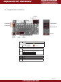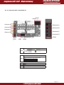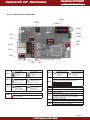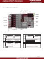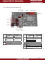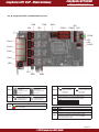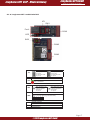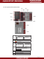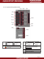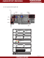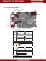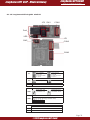
1
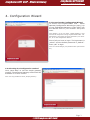
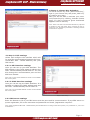
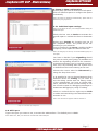
Junghanns.NET VoIP - Media Gateway
Junghanns.NET GmbH
Q UA L I T Y I N CO M M U N I C ATIONS
VoIP - Media Gateway
User Manual
1.
2.
3.
4.
5.
6.
Introduction
Hardware installation
Software installation
Configuration Wizard
Configuration Interface
Appendix
2
2
2
3
7
9
Page 1
©2009 Junghanns.NET GmbH
Junghanns.NET VoIP - Media Gateway
Junghanns.NET GmbH
Q UA L I T Y I N CO M M U N I C ATIONS
1. Introduction
The Junghanns.NET Voice over IP Media Gateway (voip-mg) provides VoIP capability to all Junghanns.
NET telecommunication cards. Junghanns.NET GSM cards are supported from version 1.0 and Junghanns.NET BRI and PRI ISDN cards from version 1.2. The application uses an opensource zaptel and
DAHDI driver and offers an Asterisk independent solution. The approved cards can now easily adopted
by any SIP or IAX2 compatible VoIP PBX (i.e. FreeSwitch, pbxnsip, Yate, Asterisk™ Business Edition®
or Microsoft Office Communication Server®). The configuration is organized by a webinterface, which
communicates with the HTTP/XML interface of voip-mg.
Manufacturers of VoIP PBXes can use the GPL licenced webinterface as a comfortable and easy first step
into integrating the HTT P/XML interface into their own user interface. Voip-mg was designed as a simple
media gateway and offers a better performance (less CPU load for the same amount of concurrent calls)
compared to Asterisk based systems, because it does not use a complex multithreading PBX core, which
makes it also ideally suited for embedded solutions.
The architecture of voip-mg is only created for running as a media gateway and provides better performance compared to Asterisk, because it does not contain an extensive PBX core. This is especially for
embedded systems very interesting.
2. Hardware installation
Make sure all your jumpers are set correctly. Do not forget to set the jumper according to your PCI slot
voltage to 3.3V or 5V.
Refer to Appendix on how to set your Jumpersettings for your Junghanns.NET card.
6.1.1 Junghanns.NET unoGSM PCI
6.1.2 Junghanns.NET duoGSM PCI
6.1.3 Junghanns.NET quadGSM PCI
6.1.4 Junghanns.NET duoBRI PCI
6.1.5 Junghanns.NET quadBRI PCI
6.1.6 Junghanns.NET octoBRI PCI
6.1.7 Junghanns.NET duoBRI PCI Express
6.1.8 Junghanns.NET quadBRI PCI Express
6.1.9 Junghanns.NET unoBRI miniPCI
6.1.10 Junghanns.NET duoBRI miniPCI
6.1.11 Junghanns.NET quadBRI miniPCI
6.1.12 Junghanns.NET singleE1 PCI
6.1.13 Junghanns.NET doubleE1 PCI
6.1.13 Junghanns.NET singleE1 miniPCI
9
10
11
12
13
14
15
16
17
18
19
20
21
22
3. Software installation
Download the Junghanns.NET VoIP Media Gateway by using this link:
http://www.junghanns.net/en/download.html
Please refer to the included „README“ file for informations on how to install the Junghanns.NET VoIP
Media Gateway.
Page 2
©2009 Junghanns.NET GmbH
Junghanns.NET GmbH
Junghanns.NET VoIP - Media Gateway
Q UA L I T Y I N CO M M U N I C ATIONS
4. Configuration Wizard
4.1 Accessing the Configuration Wizard
To access the Junghanns.NET VoiP - Media
Gateway Configuration Wizard type „http://<ip
of your VoIP Media Gateway>/index.html“ into
the address field of your browser and press
enter.
Hint: Replace „<ip of your VoIP - Media Gateway>“ with
the IP of the Computer running Junghanns.NET VoIP - Media Gateway. Java Script has to be activated in your browser, to run the Configuration Wizard.
First of all you have to login. The loginname is
„admin“ and the default password is „default“.
Press „OK“ to login.
Hint: You should change your password later (See section
5.7)
Image 4.1 Loginscreen to the Configuration Wizard
4.2 Selecting the Configuration method
Click „Next Step“ to use the simple gateway
method. The advanced gateway method will be
available in a future version.
Hint: It is only possible to select „Simple gateway“.
Image 4.2 Configuration method selection
Page 3
©2009 Junghanns.NET GmbH
Junghanns.NET GmbH
Junghanns.NET VoIP - Media Gateway
Q UA L I T Y I N CO M M U N I C ATIONS
4.3 Step 1: License-Key Activation
To add a license key click „Add license key“,
type in your license key and press „Add key“
to confirm your entry.
Now you will be able to activate your entered license keys by clicking „Activate license
keys“. If a key is correct a green checkmark
appears next to that key.
Hint: There is at least one activated license key required
to preform to the next steps. Every card has its own license key. For license-key activation a working internet
connection is required.
Image 4.3 License-Key selection
4.4 Step 2: VoIP settings
Select and configure the interface which will
be used for communicating between the Junghanns.NET VoIP - Media Gateway and your
PBX server.
4.4.1.a SIP-Interface settings
Here you can set up your SIP Interface. The
SIP address is the valid network address the
VoIP - Media Gateway should listen to. You can
also change the communication port and the
SIP from-domain.
Hint: Use 0.0.0.0 as SIP address to listen to all available
IPs of the system.
4.4.1.b IAX2-Interface settings
Here you can set up your IAX2 Interface. It is
possible to change the IAX2 address and port
the VoIP - Media Gateway should listen to.
Hint: Use 0.0.0.0 ad IAX2 address to listen to all available
IPs of the system.
Image 4.4 VoIP Settings
4.4.2 PBX server settings
Enter the Domain or IP of your PBX server and the port used for communication. If your PBX server requires registration, fill in the username and password and check „Registration required“.
Hint: If the Junghanns.NET VoIP - Media Gateway and the PBX server running on the same system, use „localhost“ or „127.0.0.1“
as Hostname
Page 4
©2009 Junghanns.NET GmbH
Junghanns.NET GmbH
Junghanns.NET VoIP - Media Gateway
Q UA L I T Y I N CO M M U N I C ATIONS
4.5 Step 3: Span configuration
At this point you see an overview of all spans.
Click on different spans to configure the spans
individually.
Hint: All spans are detected automatically. Spans with no
license key are greyed out.
4.5.1 Individual span settings
Hint: Do not forget to save your changes before editing an
additional span.
Check the box next to Active to activate the
specific span or uncheck the box to deactivate
it.
Select your Country by choosing one out of
the dropdown menu. The prefix will be set
acording to your selection.
Type in a name for the Group, used by the PBX
to specify, which spans are used to dial out.
Image 4.5 Span overview
Hint: Set the goup to value 0, to use the default group for
this span.
You have to decide if your Signalling should
be point-to-multi-point (ptmp) if available and
wether the signalling should be for customerpremises equipment (cpe) or network termination (net). By choosing auto the system tries
to determine the correct setting on its own.
Choose the correct value for Echocancel by
using the drop down menu.
It is possible for you to choose between three
different values for Debug. If you want to
see the debug results with the debug viewer
of the webinterface you have to choose XML
trace, otherwise choose console debug to use
the console output for debugging messages or
deactivate debugging by using no debug.
Check or uncheck the box right next to CLIR
to either activate Calling Line Identification Restriction or not.
Hint: Your line has to support CLIR to activate it.
Image 4.5.1 Individual span configuration
4.6. HTTP port
Type in the port you want to use, to access the webinterface. The default port is 18080.
Hint: Make sure, that you choose an unused and valid HTTP port.
Page 5
©2009 Junghanns.NET GmbH
Junghanns.NET GmbH
Junghanns.NET VoIP - Media Gateway
Q UA L I T Y I N CO M M U N I C ATIONS
4.7 Change password
Here you have the possibility to change your
password. To do so, type in your old password,
the new password and validate your new password.
Hint: Keep your password in mind, you will need it to access the webinterface.
Image 4.7 Change password
4.8 Complete the wizard
To finish the basic configuration and complete the wizard press Finish configuration. The
Junghanns.NET - Media Gateway software
needs to be restarted for changes to take effect.
Hint: After finishing the wizard and rebooting voip-mg,
you can change all configurations by using the webinterface.
Image 5.8 Complete the wizard
Page 6
©2009 Junghanns.NET GmbH
Junghanns.NET GmbH
Junghanns.NET VoIP - Media Gateway
Q UA L I T Y I N CO M M U N I C ATIONS
5. Configuration Interface
5.1 Accessing the configuration interface
To access the Junghanns.NET VoiP - Media Gateway configuration interface type „http://<ip of
your VoIP Media Gateway>/index.html“ into
the address field of your browser and press
enter.
Hint: Replace „<ip of your VoIP - Media Gateway>“ with
the IP of the Computer running Junghanns.NET VoIP Media Gateway. Java Script has to be activated for your
browser, to run the Configuration Interface.
The loginname is „admin“ and the default password is „default“. Press „OK“ to login.
Hint: You can change your password. (See section 6.5)
5.2 System status
Here you can see an overview of all active calls
and their details.
5.3 License management
See section 5.3 for information on how to activate a license key.
Image 5.1 Configuration interface
5.4 VoIP settings
Set up your VoIP as described in section 5.4.
5.5 General settings
Here you can change the used HTTP port and
your password.
Here you also can set an action URL, which will
be called when an incomming SMS arrives.
Hint: Do not forget to save your settings.
5.6 Span configuration
Configure your spans as shown in section 5.5.
Image 5.5 General settings
Page 7
©2009 Junghanns.NET GmbH
Junghanns.NET GmbH
Junghanns.NET VoIP - Media Gateway
Q UA L I T Y I N CO M M U N I C ATIONS
5.7 Debug viewer
The debug viewer shows debug informations
about these spans for which „XML trace“ is selected. See section 6.6 to get informations on
how to configurate your spans.
5.6 About voip-mg
Get some information about voip-mg.
Image 5.7 Debug viewer
Page 8
©2009 Junghanns.NET GmbH
Junghanns.NET GmbH
Junghanns.NET VoIP - Media Gateway
Q UA L I T Y I N CO M M U N I C ATIONS
6. Appendix
6.1 Jumpersettings
6.1.1 Junghanns.NET unoGSM PCI
CON1
CON2
Antenna A
Simholder A
CON4
LED
SW1 CON3
Status LED‘s
1 = Interface 2
2 = Interface 1
3 = Interface 3
4 = Interface 4
LED
Module activated
Module deactivated
Card ID switches
SW1
Use DIP switches 1 to 3 to set the card ID (very
useful for remotely identifying individual cards):
Card-ID 0
1
2
3
4
5
6
7
SW1_1 OFF ON OFF ON OFF ON OFF ON
OFF
OFF
ON
ON
OFF
OFF
ON
ON
SW1_2
SW1_3 OFF OFF OFF OFF ON ON ON ON
CON1
PCM out
CON2
PCM in
CON3
JTAG
CON4
Additional simholder connector
Page 9
©2009 Junghanns.NET GmbH
Junghanns.NET GmbH
Junghanns.NET VoIP - Media Gateway
Q UA L I T Y I N CO M M U N I C ATIONS
6.1.2 Junghanns.NET duoGSM PCI
CON1
CON2
Antenna A
Simholder A
Antenna B
Simholder B
CON4
LED
SW1
CON3
Status LED‘s
1 = Interface 2
2 = Interface 1
3 = Interface 3
4 = Interface 4
LED
Module activated
Module deactivated
Card ID switches
SW1
Use DIP switches 1 to 3 to set the card ID (very
useful for remotely identifying individual cards):
Card-ID 0
1
2
3
4
5
6
7
SW1_1 OFF ON OFF ON OFF ON OFF ON
OFF
OFF
ON
ON
OFF
OFF
ON
ON
SW1_2
SW1_3 OFF OFF OFF OFF ON ON ON ON
CON1
PCM out
CON2
PCM in
CON3
JTAG
CON4
Additional simholder connector
Page 10
©2009 Junghanns.NET GmbH
Junghanns.NET GmbH
Junghanns.NET VoIP - Media Gateway
Q UA L I T Y I N CO M M U N I C ATIONS
6.1.3 Junghanns.NET quadGSM PCI
CON1
CON2
Antenna A
Simholder A
Antenna B
Simholder B
Antenna C
Simholder C
Antenna D
Simholder D
CON4
LED
SW1
CON3
Status LED‘s
1 = Interface 2
2 = Interface 1
3 = Interface 3
4 = Interface 4
LED
Module activated
Module deactivated
Card ID switches
SW1
Use DIP switches 1 to 3 to set the card ID (very
useful for remotely identifying individual cards):
Card-ID 0
1
2
3
4
5
6
7
SW1_1 OFF ON OFF ON OFF ON OFF ON
SW1_2 OFF OFF ON ON OFF OFF ON ON
SW1_3 OFF OFF OFF OFF ON ON ON ON
CON1
PCM out
CON2
PCM in
CON3
JTAG
CON4
Additional simholder connector
Page 11
©2009 Junghanns.NET GmbH
Junghanns.NET GmbH
Junghanns.NET VoIP - Media Gateway
Q UA L I T Y I N CO M M U N I C ATIONS
6.1.4 Junghanns.NET duoBRI PCI
CON1
CON3
CON2
CON4
CON5
CON6
JP3
JP4
SW3
Port2
JP5
Port1
LED
JP1
SW2
SW1
JP2
Termination of S/T interface port X (100Ω)
NT/TE settings port X
JP1-2
Set all jumpers
to the left
to select NT mode
for port X
Set all jumpers
to the right
to select TE mode
for port X
Power feeding
enabled for port X
(PFM required)
Uses 3.3V from
the PCI bus
(only available
in 3.3V PCI slots)
SW3
Generates 3.3V
out of the 5V from
the PCI bus
(factory default)
CON1
PCM out
CON2
PCM in
CON3
Onboard PFM connector (available optionally)
Layer 1 activated
Layer 1 deactivated
Card-ID 0
1
2
3
4
5
6
7
SW3_1 OFF ON OFF ON OFF ON OFF ON
SW3_2 OFF OFF ON ON OFF OFF ON ON
SW3_3 OFF OFF OFF OFF ON ON ON ON
Power connector
Status LED
LED
Use DIP switches 1 to 3 to set the card ID (very
useful for remotely identifying individual cards):
Power feeding
disabled for port X
(factory default)
Power supply configuration
JP5
Both switches in OFF
position deactivates
termination
for port X
Card ID switches
Power feeding port X (only for NT mode)
JP3-4
Both switches in ON
position activates
termination
for port X
SW1-2
CON4
CON5
CON6
Connector for the external power feeding module
to feed S/T interfaces of up to 4 duo- or quadBRI
cards (available optionally)
Watchdog connector out
Connect to reset switch on mainboard
Watchdog connector in
Connect to reset switch on PC chassis
Page 12
©2009 Junghanns.NET GmbH
Junghanns.NET GmbH
Junghanns.NET VoIP - Media Gateway
Q UA L I T Y I N CO M M U N I C ATIONS
6.1.5 Junghanns.NET quadBRI PCI
SW4 JP3
SW3
JP4
JP5 JP7
SW5
JP6 JP8
CON1
CON2
CON4
CON5
CON6
Port4
CON3
Port3
Port2
JP9
Port1
LED
SW1
JP1
JP2
SW2
NT/TE settings port X
JP1-4
Set all jumpers
to the left
to select NT mode
for port X
Termination of S/T interface port X (100Ω)
Set all jumpers
to the right
to select TE mode
for port X
Power feeding port X (only for NT mode)
JP5-8
Power feeding
enabled for port X
(PFM required)
Uses 3.3V from
the PCI bus
(only available
in 3.3V PCI slots)
Layer 1 activated
Layer 1 deactivated
Use DIP switches 1 to 3 to set the card ID (very
useful for remotely identifying individual cards):
Power feeding
disabled for port X
(factory default)
SW5
Generates 3.3V
out of the 5V from
the PCI bus
(factory default)
CON1
PCM out
CON2
PCM in
CON3
Onboard PFM connector (available optionally)
Status LED
LED
Both switches in OFF
position deactivates
termination
for port X
Card ID switches
Power supply configuration
JP9
Both switches in ON
position activates
termination
for port X
SW1-4
Card-ID 0
1
2
3
4
5
6
7
SW5_1 OFF ON OFF ON OFF ON OFF ON
SW5_2 OFF OFF ON ON OFF OFF ON ON
SW5_3 OFF OFF OFF OFF ON ON ON ON
Power connector
CON4
CON5
CON6
Connector for the external power feeding module
to feed S/T interfaces of up to 4 duo- or quadBRI
cards (available optionally)
Watchdog connector out
Connect to reset switch on mainboard
Watchdog connector in
Connect to reset switch on PC chassis
Page 13
©2009 Junghanns.NET GmbH
Junghanns.NET GmbH
Junghanns.NET VoIP - Media Gateway
Q UA L I T Y I N CO M M U N I C ATIONS
6.1.6 Junghanns.NET octoBRI PCI
JP10 JP12
JP8
JP9 JP11
JP7
CON1
CON3
CON2
Port4+5
JP14
Port3+6
SW8
Port2+7
SW7
Port1+8
JP13
JP1-6 SW1-6
SW9
NT/TE settings port X
JP1-8
Set all jumpers
to the left
to select NT mode
for port X
Termination of S/T interface port X (100Ω)
Set all jumpers
to the right
to select TE mode
for port X
Power feeding port X (only for NT mode)
JP9-12
Power feeding
enabled for port X
(PFM required)
Uses 3.3V from
the PCI bus
(only available
in 3.3V PCI slots)
Use DIP switches 1 to 3 to set the card ID (very
useful for remotely identifying individual cards):
Power feeding
disabled for port X
(factory default)
SW9
Generates 3.3V
out of the 5V from
the PCI bus
(factory default)
CON1
PCM out
CON2
PCM in
Card-ID 0
1
2
3
4
5
6
7
SW9_1 OFF ON OFF ON OFF ON OFF ON
SW9_2 OFF OFF ON ON OFF OFF ON ON
SW9_3 OFF OFF OFF OFF ON ON ON ON
Power connector
Power feeding settings
JP14
Both switches in OFF
position deactivates
termination
for port X
Card ID switches
Power supply configuration
JP13
Both switches in ON
position activates
termination
for port X
SW1-8
Close the jumper bridges when using an external
Power Feeding Module
CON3
Connector for the external power feeding module
to feed S/T interfaces of up to 4 duo- or quadBRI
cards (available optionally)
Page 14
©2009 Junghanns.NET GmbH
Junghanns.NET GmbH
Junghanns.NET VoIP - Media Gateway
Q UA L I T Y I N CO M M U N I C ATIONS
6.1.7 Junghanns.NET duoBRI PCI Express
JP3
JP4
CON3
CON1 CON2
SW3
CON4
Port2
Port1
LED
JP1
JP2
SW1
SW2
NT/TE settings port X
JP1-2
Set all jumpers
to the left
to select NT mode
for port X
Termination of S/T interface port X (100Ω)
Set all jumpers
to the right
to select TE mode
for port X
Power feeding port X (only for NT mode)
JP3-4
Power feeding
enabled for port X
(PFM required)
Power feeding
disabled for port X
(factory default)
Both switches in ON
position activates
termination
for port X
SW1-2
Both switches in OFF
position deactivates
termination
for port X
Card ID switches
SW3
Use DIP switches 1 to 3 to set the card ID (very
useful for remotely identifying individual cards):
Card-ID 0
1
2
3
4
5
6
7
SW3_1 OFF ON OFF ON OFF ON OFF ON
SW3_2 OFF OFF ON ON OFF OFF ON ON
SW3_3 OFF OFF OFF OFF ON ON ON ON
Status LED
LED
Layer 1 activated
Layer 1 deactivated
CON1
PCM out
CON2
PCM in
CON3
Onboard PFM connector (available optionally)
Power connector
CON4
Connector for the external power feeding module
to feed S/T interfaces of up to 4 duo- or quadBRI
cards (available optionally)
Page 15
©2009 Junghanns.NET GmbH
Junghanns.NET GmbH
Junghanns.NET VoIP - Media Gateway
Q UA L I T Y I N CO M M U N I C ATIONS
6.1.8 Junghanns.NET quadBRI PCI Express
SW4
JP4
SW3
SW5
CON1
JP3
JP5
CON2 JP6
CON4
JP7
JP8
CON3
Port4
Port3
Port2
Port1
LED
JP1
JP2
SW1
SW2
NT/TE settings port X
JP1-4
Set all jumpers
to the left
to select NT mode
for port X
Termination of S/T interface port X (100Ω)
Set all jumpers
to the right
to select TE mode
for port X
Power feeding port X (only for NT mode)
JP5-8
Power feeding
enabled for port X
(PFM required)
Power feeding
disabled for port X
(factory default)
Both switches in ON
position activates
termination
for port X
SW1-4
Both switches in OFF
position deactivates
termination
for port X
Card ID switches
SW5
Use DIP switches 1 to 3 to set the card ID (very
useful for remotely identifying individual cards):
Card-ID 0
1
2
3
4
5
6
7
SW5_1 OFF ON OFF ON OFF ON OFF ON
SW5_2 OFF OFF ON ON OFF OFF ON ON
SW5_3 OFF OFF OFF OFF ON ON ON ON
Status LED
LED
Layer 1 activated
Layer 1 deactivated
CON1
PCM out
CON2
PCM in
CON3
Onboard PFM connector (available optionally)
Power connector
CON4
Connector for the external power feeding module
to feed S/T interfaces of up to 4 duo- or quadBRI
cards (available optionally)
Page 16
©2009 Junghanns.NET GmbH
Junghanns.NET GmbH
Junghanns.NET VoIP - Media Gateway
Q UA L I T Y I N CO M M U N I C ATIONS
6.1.9 Junghanns.NET unoBRI miniPCI
JP1
SW1
Port1
CON1
LED
SW2
CON2
CON3
NT/TE settings port X
JP1
Set all jumpers
to the left
to select NT mode
for port X
Set all jumpers
to the right
to select TE mode
for port X
Status LED
LED
Layer 1 activated
Layer 1 deactivated
Termination of S/T interface port X (100Ω)
SW1
Both switches in ON
position activates
termination
for port X
Both switches in OFF
position deactivates
termination
for port X
Card ID switches
SW2
Use DIP switches 1 to 2 to set the card ID (very
useful for remotely identifying individual cards):
Card-ID 0
1
2
3
SW2_1 OFF ON OFF ON
SW2_2 OFF OFF ON ON
CON1
miniPCI connector
Conenctor for the miniPCI card
CON2
Connector for the RJ45 board
CON3
PCM Connector
Page 17
©2009 Junghanns.NET GmbH
Junghanns.NET GmbH
Junghanns.NET VoIP - Media Gateway
Q UA L I T Y I N CO M M U N I C ATIONS
6.1.10 Junghanns.NET duoBRI miniPCI
JP2
JP1
SW1
SW2
Port2
CON1
Port1
LED
SW3
CON2
CON3
NT/TE settings port X
JP1-2
Set all jumpers
to the left
to select NT mode
for port X
Set all jumpers
to the right
to select TE mode
for port X
Status LED
LED
Layer 1 activated
Layer 1 deactivated
Termination of S/T interface port X (100Ω)
SW1-2
Both switches in ON
position activates
termination
for port X
Both switches in OFF
position deactivates
termination
for port X
Card ID switches
SW3
Use DIP switches 1 to 2 to set the card ID (very
useful for remotely identifying individual cards):
Card-ID 0
1
2
3
SW3_1 OFF ON OFF ON
SW3_2 OFF OFF ON ON
CON1
miniPCI connector
Conenctor for the miniPCI card
CON2
Connector for the RJ45 board
CON3
PCM Connector
Page 18
©2009 Junghanns.NET GmbH
Junghanns.NET GmbH
Junghanns.NET VoIP - Media Gateway
Q UA L I T Y I N CO M M U N I C ATIONS
6.1.11 Junghanns.NET quadBRI miniPCI
JP1-4 SW4
SW3
LED
Port4
Port3
CON1
Port2
Port1
SW2
LED
SW1
SW5
CON2
CON3
Termination of S/T interface port X (100Ω)
NT/TE settings port X
JP1-4
Set all jumpers
to the left
to select NT mode
for port X
Set all jumpers
to the right
to select TE mode
for port X
SW1-4
Layer 1 activated
Layer 1 deactivated
Both switches in OFF
position deactivates
termination
for port X
Card ID switches
Status LED
LED
Both switches in ON
position activates
termination
for port X
SW5
Use DIP switches 1 to 2 to set the card ID (very
useful for remotely identifying individual cards):
Card-ID 0
1
2
3
SW2_1 OFF ON OFF ON
SW2_2 OFF OFF ON ON
CON1
miniPCI connector
Conenctor for the miniPCI card
CON2
Connector for the RJ45 board
CON3
Connector for the RJ45 board
Page 19
©2009 Junghanns.NET GmbH
Junghanns.NET GmbH
Junghanns.NET VoIP - Media Gateway
Q UA L I T Y I N CO M M U N I C ATIONS
6.1.12 Junghanns.NET singleE1 PCI
SW1
CON2
CON1
SW2
JP1
JP2
Port1
LED
JP3
NT/TE settings port X
Set all jumpers
to the right
to select NT mode
for port X
JP1
Set all jumpers
to the left
to select TE mode
for port X
Pinout
JP2
E1 Pinout (1,2,4,5)
S2M Pinout(3,4,5,6)
Power supply configuration
Uses 3.3V from
the PCI bus
(only available
in 3.3V PCI slots)
JP3
Generates 3.3V
out of the 5V from
the PCI bus
(factory default)
Status LED‘s for port X
1, 2 = Framing
3, 4 = CRC4 Multiframing
LED1-2
established
not established
Termination of interface port X
Right switch: ON
Termination 75 Ω
SW1
Right switch: OFF
Termination 120 Ω
Card ID switches
SW2
Use DIP switches 1 to 3 to set the card ID (very
useful for remotely identifying individual cards):
Card-ID 0
1
2
3
4
5
6
7
SW2_1 OFF ON OFF ON OFF ON OFF ON
SW2_2 OFF OFF ON ON OFF OFF ON ON
SW2_3 OFF OFF OFF OFF ON ON ON ON
CON1
PCM out
CON2
PCM in
Page 20
©2009 Junghanns.NET GmbH
Junghanns.NET GmbH
Junghanns.NET VoIP - Media Gateway
Q UA L I T Y I N CO M M U N I C ATIONS
6.1.13 Junghanns.NET doubleE1 PCI
JP1
JP3
SW1
SW3
SW4
CON1
CON2
Port1
LED1
Port2
LED2
JP4 JP2 SW2
JP5
NT/TE settings port X
Set all jumpers
to the right
to select NT mode
for port X
JP1-2
Set all jumpers
to the left
to select TE mode
for port X
Pinout
E1 Pinout (1,2,4,5)
JP3-4
S2M Pinout(3,4,5,6)
Power supply configuration
Uses 3.3V from
the PCI bus
(only available
in 3.3V PCI slots)
JP5
Generates 3.3V
out of the 5V from
the PCI bus
(factory default)
Status LED‘s for port X
1, 2 = Framing
3, 4 = CRC4 Multiframing
LED1-2
established
not established
Termination of interface port X
Right switch: ON
Termination 75 Ω
SW1-2
Right switch: OFF
Termination 120 Ω
Card ID switches
SW3-4
Use DIP switches 1 to 3 to set the card ID (very
useful for remotely identifying individual cards):
Card-ID 0
1
2
3
4
5
6
7
SW3_1 OFF ON OFF ON OFF ON OFF ON
SW3_2 OFF OFF ON ON OFF OFF ON ON
SW3_3 OFF OFF OFF OFF ON ON ON ON
CON1
PCM out
CON2
PCM in
Page 21
©2009 Junghanns.NET GmbH
Junghanns.NET GmbH
Junghanns.NET VoIP - Media Gateway
Q UA L I T Y I N CO M M U N I C ATIONS
6.1.13 Junghanns.NET singleE1 miniPCI
JP2 SW1
CON1
Port1
LED
JP1
SW2
CON2
CON3
NT/TE settings port X
JP1
Set all jumpers
to the right
to select NT mode
for port X
Set all jumpers
to the left
to select TE mode
for port X
Pinout
JP2
LED
E1 Pinout (1,2,4,5)
S2M Pinout(3,4,5,6)
Status LED
Termination of interface port X
SW1
Right switch: ON
Termination 75 Ω
Right switch: OFF
Termination 120 Ω
Card ID switches
SW2
Use DIP switches 1 to 2 to set the card ID (very
useful for remotely identifying individual cards):
Card-ID 0
1
2
3
SW2_1 OFF ON OFF ON
SW2_2 OFF OFF ON ON
CON1
miniPCI connector
Conenctor for the miniPCI card
CON2
Connector for the RJ45 board
CON3
PCM Connector
Page 22
©2009 Junghanns.NET GmbH