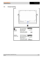
1
ATEX Version User Manual Zone 2 and Zone 21/22 POLARIS II POLARIS REMOTE POLARIS II Remote 22"/ Remote 19.1" Type 17-71V5....... Type 17-72V5....... User Manual - TRANSLATION POLARIS REMOTE POLARIS II Remote 22"/ Remote PC 19.1" Type 17-71V5-…. Type 17-72V5-…. ATEX Zone 2 ATEX Zone 21/Zone 22 Document no. 11-71V5-7D0001 Revision 0 / July, 10th, 2012 Reservation: Technical data subject to change without notice. Changes, errors and misprints may not be used as a basis for any claim for damages. Contents Page English 1 - 38 Appendix Declaration of Conformity EC Type Examination Certificates Operating Instructions for HCS Radiator GmbH Max-Eyth-Straße 16 97980 Bad Mergentheim Germany Phone: +49 7931 597-0 Fax: +49 7931 597-119 Contact: [email protected] Table of Contents 1. Basic Safety Instructions.................................................................................................................... 1 1.1 1.2 1.3 1.4 1.5 1.6 1.7 2. 3. POLARIS REMOTE POLARIS II Remote Notes on this manual .................................................................................................. 1 1.1.1 Languages....................................................................................................... 2 1.1.2 Changes to the document ............................................................................... 2 Handling the Product .................................................................................................. 2 Use in Accordance with the Intended Purpose ........................................................... 2 1.3.1 Exclusive Purpose ........................................................................................... 2 1.3.2 Improper Use ................................................................................................... 2 1.3.3 Owner’s/Managing Operator’s Obligations ...................................................... 3 Safety Instructions ...................................................................................................... 3 1.4.1 General Safety Instructions ............................................................................. 3 Safety Instructions for Operation ................................................................................ 3 1.5.1 Upkeep ............................................................................................................ 3 1.5.2 Maintenance .................................................................................................... 3 1.5.3 Inspection ........................................................................................................ 4 1.5.4 Repairs ............................................................................................................ 4 1.5.5 Commissioning ................................................................................................ 4 Ex Protection Type, Certification and Standards ........................................................ 4 Warranty ..................................................................................................................... 4 Product Description ............................................................................................................................ 6 2.1 2.2 Definition ..................................................................................................................... 6 Schematic diagram ..................................................................................................... 7 Technical Data ..................................................................................................................................... 8 3.1 3.2 3.3 3.4 POLARIS II Remote.................................................................................................... 8 3.1.1 Explosion Protection ........................................................................................ 8 3.1.2 General data.................................................................................................... 9 3.1.3 Characteristics ............................................................................................... 10 Heating (Optional)..................................................................................................... 11 3.2.1 Explosion protection ...................................................................................... 11 3.2.2 Characteristics ............................................................................................... 11 POLARIS II Remote with Integrated HCS Radiator .................................................. 12 3.3.1 Explosion protection ...................................................................................... 12 Product Labelling ...................................................................................................... 13 4. Transport and Assembly .................................................................................................................. 14 5. Installation.......................................................................................................................................... 15 4.1 4.2 4.3 5.1 5.2 5.3 Transport .................................................................................................................. 14 Intermediate Storage ................................................................................................ 14 Assembly .................................................................................................................. 14 Requirements ........................................................................................................... 15 Mechanical installation.............................................................................................. 16 5.2.1 Supporting systems ....................................................................................... 17 5.2.2 Connection cables ......................................................................................... 18 5.2.3 Rotating/Inclining ........................................................................................... 19 Electrical Installation ................................................................................................. 20 5.3.1 Installation guidelines .................................................................................... 20 Technical data subject to change without notice. 07/2012 POLARIS REMOTE POLARIS II Remote 5.4 5.5 5.6 Table of Contents Junction Box ............................................................................................................. 21 5.4.1 Open Junction Box ........................................................................................ 21 5.4.2 POLARIS Junction Box ................................................................................. 22 5.4.3 Terminal assignment X1 ................................................................................ 22 5.4.4 Terminal assignment X1 with Radiator HCS (optional) ................................. 23 5.4.5 Terminal assignment in conformance to T568B for X2.................................. 23 Connecting the Local Unit......................................................................................... 24 5.5.1 STP Cable ..................................................................................................... 24 5.5.2 Operation....................................................................................................... 25 5.5.3 Compatibility .................................................................................................. 25 EMC (Electromagnetic Compatibility) ....................................................................... 26 5.6.1 Note ............................................................................................................... 26 5.6.2 Interference suppression ............................................................................... 26 5.6.3 Shielding........................................................................................................ 26 5.6.4 Connection of shielding ................................................................................. 27 5.6.5 Examples of Shielding Connections .............................................................. 27 6. Commissioning.................................................................................................................................. 28 7. Operation............................................................................................................................................ 29 8. Troubleshooting ................................................................................................................................ 33 9. Maintenance, Inspection, Repair...................................................................................................... 34 10. Disposal.............................................................................................................................................. 35 11. Dispatch and Packaging Instructions ............................................................................................. 35 12. Accessories, Spare Parts ................................................................................................................. 36 13. Order Numbers .................................................................................................................................. 37 14. Additional Information ...................................................................................................................... 38 6.1 7.1 7.2 7.3 9.1 9.2 9.3 Final Inspection......................................................................................................... 28 Adjusting Lengths ..................................................................................................... 29 Setting up the Touchscreen ...................................................................................... 30 Calibrating................................................................................................................. 32 Maintenance intervals ............................................................................................... 34 Inspection ................................................................................................................. 34 Maintenance and Repair Work ................................................................................. 34 9.3.1 Instructions for Repairs.................................................................................. 35 Appendix: Declaration of Conformity EC Type Examination Certificate Operating Instructions for HCS Radiator Technical data subject to change without notice. 07/2012 - blank - POLARIS REMOTE POLARIS II Remote Basic Safety Instructions 1. Basic Safety Instructions 1.1 Notes on this manual Please read carefully before commissioning the devices. The user manual is a constituent part of the product. It must be kept in the direct vicinity of the device and accessible at all times to installation, operating and maintenance personnel. It contains important notes, safety instructions and test certificates which are necessary for perfect functioning when the devices are being operated and handled. It is written for technically qualified personnel. Familiarity with and strict adherence to the safety instructions and warnings in this manual are essential for safe installation and commissioning. Careful handling and consistent observation of these instructions can prevent accidents, personal injuries and damage to property. The illustrations in these operating instructions serve to make the information and descriptions more clear. They are not necessarily true to scale and may deviate slightly from the actual construction of the device. Safety instructions and warnings are specially highlighted in this manual and marked by symbols. DANGER DANGER indicates a hazardous situation which, if not avoided, will result in death or serious injury. WARNING WARNING indicates a hazardous situation which, if not avoided, could result in death or serious injury. CAUTION CAUTION indicates a hazardous situation which, if not avoided, could result in minor or moderate injury. ATTENTION ATTENTION identifies a potentially damaging situation which, if not avoided, could damage the equipment or something in its environment. Important instructions and information on effective, economical and environmentally compatible handling. Technical data subject to change without notice. 07/2012 1/38 Basic Safety Instructions 1.1.1 POLARIS REMOTE POLARIS II Remote Languages The original user manual is written in German. All other available languages are translations of the original user manual. The user manual is available in German, English and French. If you require any other languages, please ask BARTEC or request them when placing the order. 1.1.2 Changes to the document BARTEC reserves the right to alter the contents of this document without notice. No guarantee is given for the correctness of the information. In case of doubt, the German safety instructions shall apply because it is not possible to rule out errors in translation or in printing. In the event of a legal dispute, the “General Terms and Conditions” of the BARTEC group shall apply in addition. The respective up-to-date versions of data sheets, manuals, certificates, EC Declaration of Conformity may be downloaded from the “Automation Technology” product page at www.bartec-group.com or ordered directly from BARTEC GmbH. 1.2 Handling the Product The product described in these operating instructions has been tested and left the factory in perfect condition as regards meeting safety requirements. To maintain this condition and ensure that this product operates perfectly and safely, it may be used only in the manner described by the manufacturer. Appropriate transportation, suitable storage and careful operation are also essential for the perfect and safe operation of this product. The POLARIS must be installed properly and securely if it is to work perfectly and correctly. The safe and perfect mounting of the POLARIS is a precondition for faultless and correct operation. 1.3 Use in Accordance with the Intended Purpose 1.3.1 Exclusive Purpose It is used exclusively in combination with operating devices which satisfy the requirements for Overvoltage Category I. The POLARIS II Remote been designed specially for use in hazardous (potentially explosive) areas in Zone 2 or Zones 21 and 22. It is essential to observe the permissible operational data for the device being used. 1.3.2 Improper Use Any other use is not in accordance with the intended purpose and can cause damage and accidents. The manufacturer will not be liable for any use beyond that of its exclusive intended purpose. 2/38 Technical data subject to change without notice. 07/2012 POLARIS REMOTE POLARIS II Remote 1.3.3 Basic Safety Instructions Owner’s/Managing Operator’s Obligations The owner/managing operator undertakes to restrict permission to work with the POLARIS to people who: are familiar with the basic regulations on safety and accident prevention and have been instructed in the use of the POLARIS; have read and understood the documentation, the chapter on safety and the warnings. The owner/managing operator must check that the safety regulations and accident prevention rules valid for the respective application are being observed. 1.4 Safety Instructions 1.4.1 General Safety Instructions Take the device out of the hazardous area before wiping it with a dry cloth or cleaning it! Do not open devices in a hazardous area. The general statutory regulations or directives relating to safety at work, accident prevention and environmental protection legislation must be observed, e.g. the German industrial health and safety ordinance (BetrSichV) or the applicable national ordinances. In view of the risk of dangerous electrostatic charging, wear appropriate clothing and footwear. Avoid the influence of heat that is higher or lower than the specified temperature range. Protect the device from external influences! Do not expose the device to any caustic/aggressive liquids, vapours or mist! In the event of malfunctioning or damage to the enclosure, take the device out of the potentially explosive area immediately and bring it to a safe place. 1.5 Safety Instructions for Operation 1.5.1 Upkeep For electrical systems the relevant installation and operating regulations must be complied with (e.g. Directive 99/92/EC, Directive 94/9/EC and the national applicable ordinances IEC 60079-14 and the DIN VDE 0100 series)! The disposal of this equipment must comply with the national regulations on the disposal of waste. 1.5.2 Maintenance Regular servicing is not necessary if the equipment is operated correctly in accordance with the installation instructions and environmental conditions. In this context, please refer to Chapter "Maintenance, Inspection, Repair". Technical data subject to change without notice. 07/2012 3/38 Basic Safety Instructions 1.5.3 POLARIS REMOTE POLARIS II Remote Inspection Under IEC 60079-19 and EN 60079-17, the owner/managing operator of electrical installations in hazardous areas is obliged to have these installations checked by a qualified electrician to ensure that they are in a proper condition. 1.5.4 Repairs Repairs on explosion-protected operating equipment may be done only by authorised persons working in accordance with the latest developments in technology and using original spare parts. The applicable regulations must be observed. 1.5.5 Commissioning Before commissioning, check that all components and documents are there. 1.6 Ex Protection Type, Certification and Standards Markings specifying Ex protection and certification are put on the device. For Ex protection markings, see Chapter 3 "Technical Data". The POLARIS II Remote conform to Directive 94/9/EC for devices and protective systems for use to their intended purpose in potentially explosive areas (ATEX Directive). For the standards conformed to, see Chapter 3 "Technical Data". 1.7 Warranty WARNING It is not permissible to make any modifications or implement any conversions unless the manufacturer gives his approval in writing. If components other than those specified are used, protection against explosion can no longer be assured. It cannot be guaranteed that parts procured from other suppliers have been designed and produced in conformance to safety requirements and with the necessary stress tolerance. Before implementing any modifications or conversions, contact the manufacturer and obtain approval. Use only original spare parts and original expendable parts. The manufacturer grants a complete warranty only and exclusively for the spare parts ordered from him, the manufacturer. 4/38 Technical data subject to change without notice. 07/2012 POLARIS REMOTE POLARIS II Remote Basic Safety Instructions As a fundamental rule, our “General Conditions of Sale and Delivery” apply. These are made available to the owner/managing operator at the latest on formation of a contract. Guarantee and liability claims for personal injury and damage to property are excluded if they are due to one or more of the following reasons: use of the POLARIS for a purpose other than that for which it is intended. incorrect installation, commissioning, operation and maintenance. non-compliance with the instructions in the manual with respect to transport, storage, assembly, commissioning, operation and maintenance. structural modifications without our prior authorisation. inadequate monitoring of components that are subject to wear repairs done incorrectly. disasters due to the effects of foreign matter or Act of God (events outside human control). We guarantee the POLARIS and its accessories for a period of 1 year starting on the date of delivery from the Bad Mergentheim factory. This guarantee covers all parts of the delivery and is restricted to the replacement free of charge or the repair of the defective parts in our Bad Mergentheim factory. As far as possible, the delivery packaging should be kept for this purpose. In the event of such a claim, the product must be returned to us after written arrangement. The customer cannot claim to have the repairs done at the site of installation. Technical data subject to change without notice. 07/2012 5/38 Product Description POLARIS REMOTE POLARIS II Remote 2. Product Description 2.1 Definition The POLARIS II Remote 22" and 19″, is a display with keyboard and mouse which allows a PC in the safe area to be operated in hazardous areas Zones 21 and Zone 2 and Zone 22. Each POLARIS II Remote device offers the user the possibility of utilising all currently available PC-based process control systems without restrictions from the hazardous area. The devices are available as turnkey system solutions in stainless steel enclosures for wall, floor or desktop mounting. Illustration 1: POLARIS II Remote in the stainless-steel enclosure, rotatable/inclinable with touchscreen, keyboard with integrated touchpad The screen on the POLARIS II Remote 22" is a TFT display with WSXGA+ resolution (1680 x 1050 Pixels), the screen on the POLARIS II Remote 19" has SXGA resolution (1280 x 1024). It is characterised by an outstanding brilliance and very large reading angle. A touchscreen is available as an optional feature. 6/38 Technical data subject to change without notice. 07/2012 POLARIS REMOTE POLARIS II Remote Product Description Various keyboards with an integrated trackball or touchpad are available. Illustration 2: Keyboard The connection in the safe area is established by means of a local unit (included in the scope of supply). Illustration 3: Local Unit 2.2 Schematic diagram Illustration 4: Example of a possible connection Technical data subject to change without notice. 07/2012 7/38 Technical Data POLARIS REMOTE POLARIS II Remote 3. Technical Data 3.1 POLARIS II Remote 3.1.1 Explosion Protection Type 17-71V5-*** Ex protection type Zone 21/Zone 22 II 2D Ex tD A21 IP65 T100°C Product marking 0044 Certification IBExU 09 ATEX 1113 X Standards EN 61241-0:2006 EN 61241-1:2004 EN 61000-6-2:2005 EN 61000-6-4:2007 EN 61000-6-4:2007 EN 55022:2006 + A1:2007 Kl. A EN 55024:1998 + A1:2001 + A2:2003 EN 60529:1991 + A1:2000 Directives 94/9/EC 2002/95/EC 2004/108/EC Type 17-72V5-*** Ex protection type Zone 2 II 3G Ex nA IIC T5 Product marking Certification IBExU 09 ATEX B009 Standards EN 60079-0:2006 EN 60079-15:2005 EN 61000-6-2:2005 EN 61000-6-4:2007 EN 55022:2006 + A1:2007 Kl. A EN 55024:1998 + A1:2001 + A2:2003 EN 60529:1991 + A1:2000 Directives 8/38 94/9/EC 2002/95/EC 2004/108/EC Technical data subject to change without notice. 07/2012 POLARIS REMOTE POLARIS II Remote 3.1.2 Technical Data General data Construction Stainless steel enclosure Connection to the PC − Direct connection to VGA − PS/2 keyboard connection − Extension by means of an STP/S 4x2x23 AWG data communication cable Requirement for remote computer and PS/2 mouse Keyboard and mouse via PS/2 connector (optional via USB with USB PS/2 adapter) Graphics card with VGA connection: − VGA, SVGA, XGA, SXGA − WSXGA (only for 22") Vertical sync. frequency 60 to 75 Hz Conductor length up to 200 m with resolution 1680 x 1050 up to 300 m with resolution up to 1280 x 1024 Rated voltage AC 90 V to 253 V, 50 Hz to 60 Hz DC 18 V to 26 V Input voltage range AC 90 V to 253 V optional DC 24 V ± 10 % Max. power consumption Pmax. < 75 W Admissible ambient temperature Storage -25 °C to +60 °C Operation 0 °C to +50 °C Relative air humidity 5 to 95 % non-condensing Material Stainless steel Protection class IP65 Optional accessories Keyboard with integrated trackball 38 mm Keyboard with integrated trackball 50 mm Keyboard with integrated touchpad Optional Touchscreen Below +10 °C the unit has to be heated in order to guarantee the lifetime of the backlight illumination. Technical data subject to change without notice. 07/2012 9/38 Technical Data 3.1.3 POLARIS REMOTE POLARIS II Remote Characteristics POLARIS II Remote 19.1" Display − 19.1" graphics-capable TFT display − SXGA resolution 1.280 x 1.024 pixels − 16.7 million colours − Brightness 300 cd/m2 − Visible surface approx. 376 x 301 mm − Contrast 1300:1 Dimensions 610 mm x 450 mm x approx. 100 mm (width x height x depth) Weight approx. 17 kg Backlighting CFL technology, Service life approx. 50,000 hours (at +25 °C) POLARIS II Remote 22" Display Illustration 5: POLARIS II Remote with stand 10/38 − 22" graphics-capable TFT display − WSXGA+ resolution 1.680 x 1.050 pixels − 16.7 million colours − Brightness 300 cd/m2 − Visible surface approx. 474 x 296 mm − Contrast 1000:1 Dimensions (width x height x depth) 610 mm x 450 mm x approx. 100 mm Weight approx. 17 kg Backlighting CFL technology, Service life approx. 40,000 hours (at +25 °C) Technical data subject to change without notice. 07/2012 POLARIS REMOTE POLARIS II Remote Technical Data 3.2 Heating (Optional) 3.2.1 Explosion protection Type Ex protection type HCS 50 II 2 G EEx d IIC alt. dm IIC T4 II 2 D IP 65 T 135°C Product marking 3.2.2 Certification PTB 03 ATEX 1139 X Directives 94/9/EC Type HCS 50 Radiator Material black anodized aluminium, resistant to sea water Nominal voltage AC 230 V Connection Hose line EWKF 3 x 1.5 mm2; ∅ 8.1 mm; length 3 m Characteristics Switching hysteresis with anti-freezing protective device +10 °C ON +18 °C OFF Illustration 6: Radiator HCS Dimensions (length x width x height) Technical data subject to change without notice. 07/2012 52 mm x 50 mm x 155 mm 11/38 Technical Data POLARIS REMOTE POLARIS II Remote 3.3 POLARIS II Remote with Integrated HCS Radiator 3.3.1 Explosion protection The manufacturer grants a complete guarantee only and exclusively for the spare parts ordered from him, the manufacturer. The Ex protection marking on the POLARIS II Remote is changed due to the installation of the HCS radiator. The temperature class changes from T5 to T4. Type Ex protection type ATEX Zone 2 17-72V5-…. II 3 G Ex na II T4 Product marking Certification IBExU 09 ATEX 1113 X Temperature range -20 °C to +50 °C Standards EN 60079-0:2006 EN 60079-15:2005 EN 61000-6-2:2005 EN 55022:2006 + A1:2007 Kl. A EN 55024:1998 + A1:2001 + A2:2003 EN 60529:1991 + A1:2000 Directive 12/38 94/9/EC 2002/95/EC 2004/108/EC Technical data subject to change without notice. 07/2012 POLARIS REMOTE POLARIS II Remote 3.4 Technical Data Product Labelling Type label for Zone 2 Type label for Zone 21/22 Technical data subject to change without notice. 07/2012 13/38 Transport and Assembly POLARIS REMOTE POLARIS II Remote 4. Transport and Assembly 4.1 Transport CAUTION This device is heavy (approx. 17 kg). There is a risk of injury if it is lifted or moved incorrectly. 4.2 You will need help from others when transporting it. Intermediate Storage ATTENTION Incorrect storage can cause damage! 4.3 Comply with the correct storage temperatures. Keep the POLARIS free of moisture. Assembly Before assembling the device, make sure you have all the components and documents. Scope: 1 x POLARIS II Remote 1 x Local Unit 2 x RJ45 plug (Phoenix) 1 x Connection cable VGA/PS2 1 x Connection cable RS232 for touchscreen 1 x Driver CD for touchscreen 1 x User Manual POLARIS II Remote Optional: Supporting system for floor, wall or table mounting Radiator HCS Not enclosed: Assembly material Cable for voltage supply and data line A written report of any transport damage or missing items must be given to the appointed forwarder and to BARTEC GmbH immediately on receipt of the delivery. BARTEC GmbH’s warranty conditions do not cover damage caused by incorrect storage. Required Tools: 1 x hex key 5 mm (to fix the supporting system in place) 1 x hex key 3 mm (for opening the junction box) 14/38 Technical data subject to change without notice. 07/2012 POLARIS REMOTE POLARIS II Remote 5. Installation Installation We recommend setting up the complete system under laboratory conditions and testing it before it is permanently installed. If a long connection cable is not available, please use a patch cable to test the basic functions. DANGER Electrostatic charging through a stream of particles. There is a risk of fatal injury in an explosive atmosphere! 5.1 Make sure there are no highly energetic charging mechanisms at the user interface on the display unit or its accessories. Do not install the device in the stream of particles. Requirements − The surface underneath and the fastening means for the supporting system must be designed to support the weight of the POLARIS (approx. 17 kg). − Choose the optimum height for operating the POLARIS. − Ensure good lighting conditions for a perfectly legible display (no direct exposure to the sun’s rays). − Do not mount in direct proximity to switching or current changing devices. − Do not install the device in the stream of particles. − The POLARIS must be integrated in the equipotential bonding. − At ambient temperature below 0 °C, the POLARIS has to be heated (Heating on request). − Below +10°C the POLARIS needs to be heated to maintain the lifetime of the backlight illumination. − The supply and data line(s) are laid in the supporting system. − The supporting system is fastened by means of the flange plate (see the following illustrations). Technical data subject to change without notice. 07/2012 15/38 POLARIS REMOTE POLARIS II Remote Installation 5.2 Mechanical installation CAUTION This device is heavy (approx .17 kg). Risk of injury if lifted or moved incorrectly. Movable enclosure parts on the swivel-mounted enclosure. There is a risk of injury by hands being crushed. 3 people are required to set up the POLARIS. Hold up the POLARIS on both sides (two people), so that the third person can lay the supply and data line(s) in the supporting system. When lifting the POLARIS, always pick up the swivel-mounted adapter and enclosure together. Make sure that your fingers do not get caught between the swivel adapter and the enclosure as you set up the POLARIS. Install the POLARIS on a load-bearing and stable base and use suitable mounting material to fix it in place. Only qualified personnel, i.e. trained skilled specialists will have the necessary specialised know-how to be able to perform all the mechanical work. Familiarity with and the technically perfect implementation of the safety instructions described in this manual are preconditions for safe installation and commissioning. Work steps: 16/38 − Have the supply and data line(s) ready. − Refer to the drilling patterns to prepare to assemble the selected supporting system (see Chapter 5.2.1 Illustrations 7 - 9) − Lay the supply and data line(s) in the supporting system. − Fasten the supporting system. − Set up the POLARIS. Technical data subject to change without notice. 07/2012 POLARIS REMOTE POLARIS II Remote 5.2.1 Installation Supporting systems The POLARIS devices are ready-to-operate system devices in a rotatable/inclinable stainless-steel enclosure with different supporting systems. Floor mounting Illustration 7: Drilling pattern - supporting system for floor mounting Wall mounting Illustration 8: Drilling pattern - supporting system for wall mounting Technical data subject to change without notice. 07/2012 17/38 POLARIS REMOTE POLARIS II Remote Installation Table mounting Illustration 9: Drilling pattern - supporting system for table mounting 5.2.2 Connection cables − The connection cables to the POLARIS are laid in the supporting system. − To facilitate the wiring of the supply and data line(s), there are three cable glands on the back of the enclosure on the POLARIS II Remote and a sealing plug (the variant without keyboard has two cable glands and two sealing plugs). If necessary, the sealing plugs can be replaced by M20x1.5 cable glands (IP65 type of protection). − In addition, the POLARIS II Remote has four further cable glands on the underside of the enclosure. Cable glands that are not used are closed with a sealing plug (IP65). Illustration 10: Cable entries with sealing plugs on the underside of the enclosure DANGER Open cable glands or openings will render the IP65 protection ineffective. There is a risk of a fatal injury in an explosive atmosphere! 18/38 Cable glands/openings that are not used must be closed with sealing plugs. Technical data subject to change without notice. 07/2012 POLARIS REMOTE POLARIS II Remote 5.2.3 Rotating/Inclining Installation Rotating − The POLARIS is fixed in position on the supporting system by means of two hexagon socket-head screws (M10) and a handle screw. − The angle of rotation can be changed once the screws have been loosened. Tools: hex key 5 mm Illustration 11: Swivel-mounted adapter Inclining − The POLARIS is fixed in position by means of the two side handle screws. − The angle of inclination can be changed once both handle screws have been loosened. Illustration 12: Side handle screw Technical data subject to change without notice. 07/2012 19/38 Installation POLARIS REMOTE POLARIS II Remote 5.3 Electrical Installation 5.3.1 Installation guidelines Only qualified personnel, i.e. trained electricians will have the required specialised knowledge to be able to do all the electrical work. Familiarity with and the technically perfect implementation of the safety instructions described in this manual are preconditions for safe installation and commissioning. 20/38 (1) The user may do only the wiring at the terminals that are accessible to him/her. (2) More extensive dismantling work on the device may be done only by the manufacturer or by persons authorised by the manufacturer for this purpose. The device is factory-sealed. Never open it! (3) The PE connection must be joined to the equipotential bonding conductor in the explosion-hazardous area. (4) The safety and accident prevention regulations applicable to the respective individual case must be observed. (5) Devices must be properly installed first before they may be operated. (6) It must be possible at all times to disconnect the devices from the voltage supply (in fixed installations by means of an all-pole mains isolating switch or fuse). (7) It must be ensured that the supply voltage agrees with the specifications in the manual and the tolerances must be observed. (8) Malfunctioning cannot be ruled out if levels exceed or drop below the specified tolerances. (9) If there is a power failure or if the power supply is interrupted, make sure the system has not been put into a dangerous, undefined condition. (10) EMERGENCY STOP mechanisms must remain effective throughout all modes and states of operation. (11) Connection cables (particularly data transmission cables) must be selected and laid in a way that ensures that capacitive and inductive interference will not have any adverse effect on the equipment. Appropriate measures must be taken to handle line interruptions to prevent any undefined states occurring. (12) Wherever malfunctioning can cause material damage or personal injuries, additional external safety circuits must be provided (e.g. limit switch, mechanical interlocking devices etc.). Technical data subject to change without notice. 07/2012 POLARIS REMOTE POLARIS II Remote Installation 5.4 Junction Box 5.4.1 Open Junction Box DANGER Risk of a fatal injury by an electric shock, when the enclosure or junction box is open. Turn off the voltage supply before connecting the POLARIS and accessories. Work steps − Loosen all hex-socket countersunk screws (4 x 10) at the back of the enclosure. (Connection terminal compartment for supply and data line(s)). Required tools: hex key 3 mm. Illustration 13: Back wall of the POLARIS II Remote rear wall − Remove the back of the enclosure without damaging the seals (Careful, the back of the enclosure is connected to the enclosure’s equipotential bonding!) − Run the supply and data line(s) through the cable glands into the enclosure. − Select a sufficient length of cable so that the cables will not be damaged when the enclosure is rotated or tilted. It is also possible to mount the cable glands onto the underside of the POLARIS (see Chapter 5.2.2, illustration 10). − Connect the supply and data line(s) (see Chapter 5.4.x). − Close the back of the POLARIS enclosure after installation. Technical data subject to change without notice. 07/2012 21/38 Installation 5.4.2 POLARIS REMOTE POLARIS II Remote POLARIS Junction Box Illustration 14: POLARIS II Remote junction box 5.4.3 Terminal assignment X1 Terminal Interface AC/DC Signal Description X1-1 Supply PE Internal protective, protective earth X1-2 Supply L1/+ AC 230 V ± 10 %/DC 24 V ± 10 % X1-3 Supply N Neutral conductor X1-4 Supply PE Protective earth X1-5 PS2/supply 5V RD/PK X1-6 PS2/supply GND BR/GN X1-7 PS2/data keyboard Kb_Data BU X1-8 PS2/data keyboard Kb_CLK WH X1-9 PS2/data mouse Ms_Data BK X1-10 PS2/data mouse Ms_CLK YE X1-11 PS2/shield Shield Black “shrinkable tubing” Illustration 15: Terminal assignment X1 22/38 Technical data subject to change without notice. 07/2012 POLARIS REMOTE POLARIS II Remote 5.4.4 Installation Terminal assignment X1 with Radiator HCS (optional) Terminal Interface AC/DC Signal Description X1-1 Supply PE Internal protective, protective earth X1-2 Supply L1/+ AC 230 V ± 10 %/DC 24 V ± 10 % X1-3 Supply N Neutral conductor X1-4 Supply PE Protective earth X1-5 Heating L1/+ AC 230 V ± 10 %/DC 24 V ± 10 % X1-6 Heating N Neutral conductor X1-7 Heating PE Protective earth X1-8 PS2/data keyboard 5V RD/PK X1-9 PS2/data keyboard GND BR/GN X1-10 PS2/data mouse Kb_Data BU X1-11 PS2/data mouse Kb_CLK WH X1-12 PS2/shield Ms_Data BK X1-13 PS2/data keyboard Ms_CLK YE X1-14 PS2/data keyboard Shield Black “shrinkable tubing” Illustration 16: Terminal assignment X1 for POLARIS with heating 5.4.5 Terminal assignment in conformance to T568B for X2 Assembly RJ45 PIN1 Technical data subject to change without notice. 07/2012 PIN Colour Interface Signal Function 1 OG/WH KVM Pair 1 T1 Blue Video 2 OG KVM Pair 1 R1 Blue Video 3 GN/WH KVM Pair 2 T2 Green Video 4 BU KVM Pair 2 R3 Red Video 5 BU/WH KVM Pair 3 T3 Red Video 6 GN KVM Pair 3 R2 Green Video 7 BN/WH KVM Pair 4 T4 PS2/Data 8 BN KVM Pair 4 R4 PS2/Data 23/38 POLARIS REMOTE POLARIS II Remote Installation 5.5 Connecting the Local Unit Illustration 17: front view Illustration 18: rear view This enables your PC to be operated remotely. The serial interface must be connected for the POLARIS II Remote with touchscreen. 5.5.1 STP Cable This allows your PC to be operated from a remote location. The POLARIS II Remote with STP cable facilitates the operation of the PC at a distance of up to 300 m depending on the resolution. You need just a single CAT.5, CAT.6 or CAT.7 cable, 4x2 twisted pairs (installation cable!- patch cables are not suitable for long cable runs!). Cable equalisation adjustable on the keyboard compensates for a loss of quality due to the cable length. Buffered signals ensure uninterrupted work with the PC. Keyboard and mouse emulation allow plug&play functionality. The PC boots under all conceivable circumstances and the plug&play initialisation of keyboard and mouse is ensured in the same way. 24/38 Technical data subject to change without notice. 07/2012 POLARIS REMOTE POLARIS II Remote Installation A local unit from the ACU series from the BLACK BOX company is used in conjunction with the POLARIS II Remote. ATTENTION Please read this manual carefully and comply with the manufacturer’s warnings also. More information on the device can be found at the following link: http://www.all-about-kvm.com/marketing/infos/ACU2xxxA_Manual_Quickreference.zip 5.5.2 Operation The local units are easy to operate and they work with all operating systems. There is no need for any software. Connect the two devices as described and the devices will be ready for use. The plug&play initialisation of keyboard and mouse allows the PC to be booted correctly even if the POLARIS II Remote is switched off or the keyboard and/or mouse is disconnected. 5.5.3 Compatibility To enable work in various environments with hardware from very different manufacturers, this product has a great variety of functions and was tested with a large number of different devices. Nevertheless, it is not possible to guarantee that it will work correctly with every keyboard/mouse/monitor and every motherboard on the market. As PS2 connections are becoming increasingly rare in computers today, a USB to PS2 adapter was included in our range. Likewise we offer you an external voltage supply for the KVM extender for worst case scenarios. Please ask a BARTEC salesperson with responsibility for this area. Technical data subject to change without notice. 07/2012 25/38 POLARIS REMOTE POLARIS II Remote Installation 5.6 EMC (Electromagnetic Compatibility) 5.6.1 Note This is a class A unit and can cause radio interference in residential areas; if it does, the owner/managing operator may be required to implement suitable measures and pay for loss or damage. Only shielded conductors may be used as connecting conductors. This applies both to the data line and to all other conductors too. The data lines must be stranded in pairs. Example 4 x 2 x 0.75 mm² LIYCY TP. As far as possible, separate conductors should be used for power supply and data. 5.6.2 Interference suppression Certain basic measures must be taken to ensure freedom from interference when the POLARIS are installed: 5.6.3 26/38 − The interference voltages coupled into the device via power, data and signal line and the electrostatic voltage caused by contact are to be dissipated through the equipotential bonding. − The installation point should be as far as possible away from fields of electromagnetic interference. This is especially important if there are frequency converters in the vicinity. Under certain circumstances will it be advisable to set up partitions to isolate the graphic display from interference. − If inductive devices are fitted in the vicinity (e.g. contactor, relay or solenoid coils), especially if they are powered from the same source, protective circuits (e.g. RC elements) must be installed. − Power supply and data cables must be laid so as to avoid interference. This can be achieved, for example, by avoiding laying such cables in close proximity to highcurrent carrying cables. − Only cables with braided shielding should be used (recommended cover density > 80%). − Sheet shielding should not be used. − Generally, connection of the shielding at both ends results in optimum damping of all interference frequencies. − Connection of the shielding at one side only may be more advisable if a difference in potential exists and no equipotential bonding cable can be laid. Shielding Technical data subject to change without notice. 07/2012 POLARIS REMOTE POLARIS II Remote 5.6.4 Installation Connection of shielding A low impedance connection to the circuit protective conductor is important to ensure a low current fault path. When sub-D connectors are used, the shielding should always be connected to the metal casing of the sub-D plug. The plug casing of some controllers is not always well connected to earth. In such cases it may prove advantageous to insulate the shielding from the sub-D plug of the controller and connect it directly to the protective earth conductor by means of a cable that should be kept as short as possible (0.75 mm² …1.5 mm²). 5.6.5 Examples of Shielding Connections Connection of shielding at one end of connecting cables between the host and the POLARIS: POLARIS PLC Shield Difference in potential Earth Illustration 19: Shielding connection Connection of the shielding at one end only is recommended when there is inadequate equipotential bonding, or none at all. In such cases an electrically isolated power supply unit must be used. Before the equipment goes into service the directions from the controller manufacturer regarding proper assembly and operation must be read carefully. They should then be applied taking full account of the recommendations we make here. Technical data subject to change without notice. 07/2012 27/38 POLARIS REMOTE POLARIS II Remote Commissioning 6. Commissioning For electrical systems the relevant installation and operating specifications (e.g. Directives 99/92/EC and 94/9/EC, BetrSichV and the applicable national ordinances, IEC 60 079-14 and the DIN VDE 0100 series) must be observed. The operator of an electrical system in a hazardous environment must keep the operating equipment in an orderly condition, operate it correctly, monitor it and do the required maintenance and repairs. Before commissioning the devices, check that all components and documents are there. 6.1 Final Inspection The following conditions must be met before the device may be commissioned: − Check the POLARIS for damage to sealings, cable connections or glass pane. − Check the supply and data line(s). − Check all cable glands to ensure that they have been tightened securely and that all open cable entries have been closed with a sealing plug. DANGER An open enclosure will render the iP65 protection ineffective. There is a risk of a fatal injury in an explosive atmosphere! Make sure that the back wall of the POLARIS is closed and all screws have been tightened correctly. ATTENTION 28/38 If the ambient temperature is under 0 °C, the heating must be put into operation 24 hours before the POLARIS is switched on. If the POLARIS is switched off at ambient temperatures under 0 °C, an advance heating time of 24 hours must be observed again. Once the heating is switched on, the POLARIS can be used at ambient temperatures from -20 °C to +50°C. Technical data subject to change without notice. 07/2012 POLARIS REMOTE POLARIS II Remote 7. Operation Operation Once the final inspection has been carried out, the device can be put into operation. The POLARIS series does not have any ON/OFF switch. An external power switch is used to turn the device on and off. 7.1 Switch on the POLARIS and the computer. The computer’s screen appears on the POLARIS. Adjusting Lengths Run Quick Startup. For this purpose, connect all cables as described and start the computer again. Technical data subject to change without notice. 07/2012 29/38 Operation 7.2 30/38 POLARIS REMOTE POLARIS II Remote Setting up the Touchscreen Autostart. For the POLARIS II Remote, select the "serial controller". Continue with Select the directory. Continue with . . Technical data subject to change without notice. 07/2012 POLARIS REMOTE POLARIS II Remote Operation Continue with . Start installation by clicking on . Technical data subject to change without notice. 07/2012 The computer must be restarted after installation. 31/38 POLARIS REMOTE POLARIS II Remote Operation 7.3 Calibrating The "TouchScreen Control Panel" can be called up via the start menu. Accept the settings by clicking on "4Points, mode 1". Start calibration by clicking on . Follow the menu and click on and hold for approx. 2 seconds all points indicated in the respective corners of the screen. Confirm the opening window by clicking on “YES“. If acknowledged with “No”, the calibration will not be saved. If the touchscreen setting is not precise enough, the calibration can be repeated with a higher mode also. 32/38 Technical data subject to change without notice. 07/2012 POLARIS REMOTE POLARIS II Remote 8. Troubleshooting Troubleshooting All actions required to adapt the device in the best way possible are implemented by using the keyboard on the POLARIS II Remote. For this purpose, the command mode is called up with the aid of the hotkey sequence. The settings are modified here and particular operating modes are configured (see the BLACKBOX manual for Technical Details). No image Displaced image Distorted image Colours are not displayed correctly e.g. red instead of blue. Technical data subject to change without notice. 07/2012 − Check the voltage to the POLARIS II Remote − Press the Num-Lock key − The status is displayed by means of LED − Check voltage to the local unit. − Connect the mouse or keyboard. − No reaction, connect the external power pack. − Check image correction − Proceed in accordance with the Quick-Start instructions. − Check the data communication cable. − Measure the data communication cables to see if there is any short circuit or accidental ground. − Check wiring. − Two cores in the data line are connected incorrectly 33/38 Maintenance, Inspection, Repair 9. POLARIS REMOTE POLARIS II Remote Maintenance, Inspection, Repair Only trained and qualified personnel may commission and do maintenance work on the POLARIS! Trained qualified personnel are people who are familiar with the installation, assembly, commissioning and operation of the POLARIS, have been instructed about the risks and have the appropriate qualifications by virtue of the work they do. 9.1 Maintenance intervals The mechanical status of the devices should be checked at regular intervals. The length of the maintenance intervals depends on the ambient conditions. We recommend checking at least once a year. Regular maintenance is not necessary if operated appropriately in conformance with the installation instructions and with due consideration to the ambient conditions. DANGER Prevent electrostatic charging in hazardous (potentially explosive) areas. There is a risk of a fatal injury in an explosive atmosphere! 9.2 Take devices out of hazardous areas before wiping them dry or cleaning them! Inspection Under IEC 60079-17, IEC 60079-19, EN 60079-17 and EN 60079-19, the owner/ managing operator of electrical installations in hazardous areas is obliged to have these installations checked by a qualified electrician to ensure that they are in a proper condition. 9.3 Maintenance and Repair Work Adhere to the applicable regulations under Directive 99/92/EC, IEC 60079-19 and IEC 60079-17 when servicing, doing maintenance work on and testing associated operating equipment! Assembly/disassembly, operating and maintenance work may be done only by trained specialists. The statutory rules and other binding directives on workplace safety, accident prevention and environmental protection must be observed. 34/38 Technical data subject to change without notice. 07/2012 POLARIS REMOTE POLARIS II Remote 9.3.1 Repair, Disposal, Dispatch, Packaging Instructions for Repairs If you wish to send in a defective device for repair, please read the RMA procedure guidance first. Then fill in and sign the RMA (Return Merchandise Authorisation) form and send it to our "Retouren Center". E-mail: [email protected] Fax: +49 7931 597-119 We cannot guarantee any contractually agreed processing times for devices that are sent in without an RMA number. The RMA guide and the RMA form are available on our homepage for downloading. http://www.bartec.de > Quality and culture > RMA form Have you any questions? Write us an e-mail or call us. 10. E-mail: [email protected] Phone: +49 7931 597-444 Disposal The component of the POLARIS contains metal, plastic parts and electronic components. The statutory requirements for electrical scrap must be observed therefore (e.g. disposal by an approved disposal company). 11. Dispatch and Packaging Instructions ATTENTION Sensitive Devices ! Take the device’s maximum weight into account when selecting the packaging and mode of transport. Technical data subject to change without notice. 07/2012 35/38 Accessories Spare Parts 12. POLARIS REMOTE POLARIS II Remote Accessories, Spare Parts Name Order No. Keyboard including stainless steel enclosure Keyboard with integrated trackball 38 mm Keyboard with integrated trackball 50 mm Keyboard with integrated touchpad Stand for floor mounting Material: Stainless steel DIN 1.4301 Rotatable Height approx. 1 m, Diameter 80 mm Desk mounting for stainless steel enclosure Material: Stainless steel DIN 1.4301 Rotatable Height approx. 140 mm, Diameter 80 mm 05-0005-0068 Supporting arm for wall mounting Material: Stainless steel DIN 1.4301 Rotatable Length 580 mm 05-0005-0058 Local Unit/STP cable (Black Box brand) with RS232 interface 03-9840-0091 Power pack for Local Unit for CAT cable with keyboard usage 03-9911-0018 19" Rack mounting for Local unit with CAT cable with fibre optic cable 03-8931-0037 03-8931-0038 USB to PS/2 converter for mouse and keyboard Non Ex 03-9829-0007 VGA, PS/2 keyboard, PS/2 mouse, Length: 3 m 05-0068-0218 CAT.7 4x2x23 AWG, outer diameter: 7.9 mm CAT.7 4x2x22 AWG, outer diameter: 18 mm; armoured 02-4082-0002 KVM cable LAN STP cable 02-4082-0004 Note: Additional cable glands for armouring necessary 36/38 Technical data subject to change without notice. 07/2012 POLARIS REMOTE POLARIS II Remote 13. Order Numbers Order Numbers Technical data subject to change without notice. 07/2012 37/38 Additional Information 14. 38/38 POLARIS REMOTE POLARIS II Remote Additional Information Technical data subject to change without notice. 07/2012 Appendix Declaration of Conformity 11-71V5-7C0001 11-72V5-7C0001 EC Type Examination Certificate IBExU09ATEX009 IBExU09ATEX1113X Operating Instructions Radiator HCS Type 27-20..-…./…. with Declaration of Conformity HCS Radiator Type 27-20 ..-…./…. Operating Instructions 3 Technical data Rated voltage maxi. AC 250 V Permissible operating voltage maxi. AC 265 V Rated current (in compliance maxi. 10 A with VDE 0298) Ambient temperature -50 °C up to +60 °C Operating temperature range -50 °C up to +180 °C without thermostat Operating temperature range with thermostat (with type of -50 °C up to +80°C heater 27-2261 …./…. and 27-2263 …./….) Operating temperature range with thermostat (with type of -50 °C up to +180°C heater 27-226A …./…. and 27-226B …./….) Installation position: Vertical flow through fins Switching capacity of 16 A, AC 250/400 V thermostat and failure alarm Special voltages are possible with appropriate output adaptation and component selection. Conformity to standards EN 60079-0: 2006 EN 55014-1: 2006 EN 60079-1: 2004 EN 60529: 1991+A1: 2000 EN 60079-18: 2004 EN 61241-0: 2006 EN 61241-1: 2004 EN 61241-18: 2004 1 Use 4 The HCS radiators are produced in compliance with Directive 94/9/EC and approved for direct heating by flange mounting and/or for room heating by natural convection. They can be used in hazardous areas in accordance with the Ex marking specified under point 2. The standard version has thermostats integrated in the connection cable as protection against frost. Versions without thermostat can be used as protection against condensation or with an external controller for temperature maintenance. 2 Explosion protection 21-2000-7D0001-07/10-BEH-292957 EC Type Approval Certificate: PTB 03 ATEX 1139 X Ex marking: (depending on the type being used: the following maximum Ex protection type) II 2G Ex D IIC or dm IIC resp. T4, T3 Installation During unpacking and transport, take care not to bend or place weights on the connection cable. The radiator must be mounted as shown in point 9 with fins in a vertical position in order to ensure effective convection. The specified minimum distances from the ground, walls and neighbouring devices must be adhered to. The connection cable must be firmly laid with mechanical protection up to the entry into the terminal box provided by the customer while complying with the permissible bending radius of 5 x external diameter. If connected in a hazardous area, it must be connected through an enclosure that meets the requirements of the types of protection specified in EN 60079-0 Section 1. During installation the max. permissible temperatures of the neighbouring components must be observed. When determining the operating temperature, the max. permissible ambient temperature, self-heating and perhaps the heat conduction (medium) must be taken into account. In Types 27-2061…./…. and Type 27-2063 The thermostat must be built into an enclosure that corresponds to the requirements in 60079-18 section 7.1. A 16-A fuse in conformance to DIN 41571 or IEC 60127 must be connected upstream as a protection against short circuits. This fuse may be accommodated in the associated supply device or must be connected upstream separately. The safety rated voltage must be equal to or greater than the thermostat’s specified nominal voltage. II 2D Ex tD or tDmD resp. A21 IP 65 T 135 °C, T 200 °C BARTEC GmbH Max-Eyth-Straße 16 D-97980 Bad Mergentheim Tel.: +49 7931 597-0 Fax: +49 7931 597-119 [email protected] www.bartec.de Reservation Technical data subject to change without notice. Changes, errors and misprints may not be used as a basis for any claim for damages. 1/4 HCS Radiator Type 27-20 ..-…./…. Operating Instructions The connection capacity of the automatic circuit breaker must be equal to or greater than the maximum assumable shortcircuit current at the site of installation. The equipotential bonding or grounding must be ensured by mounting the thermostat onto the entire system. There is the optional possibility of using external thermostats that have a separate EC Type Examination Certificate. 5 9.1 HCS From customer Connection The radiator may be connected and secured only by a specialist complying with the “rated voltage” and “rated current” specified on the type label: The radiator has reached its rated power once the operating voltage = rated voltage. Mains voltage fluctuations up to 10 % are permissible then. To protect against short-circuits and for cable protection, circuit breakers with type B characteristic up to 16 A can be used. Additional equipotential bonding is necessary. The terminal block provided for this has the earthing sign. Residual current devices increase safety for people and protection for equipment and are therefore recommended. When the radiator has been installed in accordance with the guidelines given under points 3 and 4 and it has been ensured that effective convection is not obstructed at any time by inadmissible covers, the radiator may be switched on. A temperature fuse will permanently open the heating circuit if these installation instructions are not observed. 8 Safety Instructions When mounted in an exposed position, there is a risk of injury from the rib ends and hot surfaces: • Max. 160 °C for T3 heaters • Max. 100 °C for T4 heaters • The thermostat must be mounted assembled in the air 21-2000-7D0001-07/10-BEH-292957 9 min. 10 Thanks to its type of construction, the radiator does not require any maintenance work. The intervals for the performance and safety tests can be freely selected in accordance with the owner/managing operator’s applicable regulations. min. 60 Maintenance 9.1.2 with wiring box provided by the customer outside min. 50 7 9.1.1 with wiring box provided by the customer inside min. 50 Commissioning Installation position and minimum spacing When assembling, the following must be observed: • the ribs must be vertical • the minimum distance from the enclosure must be adhered to, see 9.1.1 and 9.1.2 • the type label must stay legible • measurements must be given in mm BARTEC GmbH Max-Eyth-Straße 16 D-97980 Bad Mergentheim Tel.: +49 7931 597-0 Fax: +49 7931 597-119 [email protected] www.bartec.de min. 10 6 Thermostat: Observe minimum spacing from the enclosure, see 9.1.1 and 9.1.2 Reservation Technical data subject to change without notice. Changes, errors and misprints may not be used as a basis for any claim for damages. 2/4 Operating Instructions HCS Radiator Type 27-20 ..-…./…. Dimensions 10 Wiring diagram Fastening parts are contained in the scope of supply. Thermostat Heizkörper HCS 11 Service address BARTEC GmbH Max-Eyth-Straße 16 D-97980 Bad Mergentheim Tel. Fax + 49 7931 597-0 + 49 7931 597119 21-2000-7D0001-07/10-BEH-292957 E-mail: [email protected] Web: www.bartec.de BARTEC GmbH Max-Eyth-Straße 16 D-97980 Bad Mergentheim Tel.: +49 7931 597-0 Fax: +49 7931 597-119 [email protected] www.bartec.de Reservation Technical data subject to change without notice. Changes, errors and misprints may not be used as a basis for any claim for damages. 3/4 Operating Instructions BARTEC GmbH Max-Eyth-Straße 16 D-97980 Bad Mergentheim HCS Radiator Type 27-20 ..-…./…. Tel.: +49 7931 597-0 Fax: +49 7931 597-119 [email protected] www.bartec.de Reservation Technical data subject to change without notice. Changes, errors and misprints may not be used as a basis for any claim for damages. 4/4 BARTEC protects people and the environment by the safety of components, s y s t e m s BARTEC GmbH Germany Max-Eyth-Straße 16 97980 Bad Mergentheim Phone: +49 7931 597-0 Fax: +49 7931 597-119 [email protected] www.bartec-group.com EN_11-71V5-7D0001- Automation Technology - July 2012 and plants.