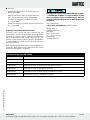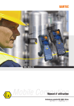
1
Aufkleber
21-1780-7D001/E-05/2013-BEH-D278563
MSB and HSB Cold applied technology
Installation and Operation
Connection and Remote End Termination for
MSB and HSB heating system
Type 27-1780-..10/.... and Type 27-1980-1.10/....
DE 2/16
21-1780-7D001/E-05/2013-BEH-D278563
HSB and MSB
Operating instructions
1. Product description
The Ex-heating system HSB type 27-1780-**10/**** with the HSB
(type 07-5803-***A) self-limiting parallel heating tape or the Exheating system MSB Typ 27-1980-1*10-****/**** with the MSB
(type 07-5804-2**X and type 07-5804-2**Y) self-limiting parallel
heating tape, assembled with a connection and remote end termination
system (installation kit 05-0091-0129** or kit 05-0091-0135**) in cold
connection technology, is set up as a stationary resistance heating
system for pipelines or containers in hazardous areas.
The Ex-heating system HSB type 27-1780-**10/**** is used in
Zone 1, 2, 21 or Zone 22 according to the certified explosion group II
and temperature classes T2, T3, T4. The Ex-heating system MSB type
27-1980-1*10-****/**** is used in Zone 1, 2, 21 or Zone 22 according
to the certified explosion group II and temperature classes T3 or T4.
After assembly the supply wires and the twisted protective braid of the
heating tape are always to be connected to terminals in an enclosure with
“increased safety“ protection class in conformance to the relevant
standards (EN 60079-0 and EN 60079-7).
Maximum operation temperature
HSB +120 °C heating circuit energized
MSB +110 °C heating circuit energized
Maximum withstand temperature
(Applied termination component)
HSB +190 °C heating circuit de- energized
MSB +130 °C heating circuit de- energized
Ambient temperature range
HSB -55 °C up to +55 °C
MSB -40 °C up to +55 °C
(cut- in and ambient work- piece
and installation conditions)
Max. cross section of the supply cable
6 mm²
4 mm2 (in combination with PLEXO)
Protection class
IP 65
3. Safety Instructions
Please read carefully as this operation manual will be
applicable for connection and termination with the cold
applied technology described for HSB and MSB heating
cables. Technical limits are to be found in the type
examination certificates.
2. Technical data
Rated voltage
208 to 254 V
Rated current
max. 32 A
The requirements under EN 60519-1 and EN 60519- 2 must be adhered
to. Thermal Safety Class 0 under EN 60519-2 Section 13 is met by
the heating tapes design characteristics. The copper braid with a
resistance of < 18.2 W/km is suitable as a protective conductor.
The minimum requirements for circuits protection and control
requirements are defined in IEC/EN 60079-30-1 clause 4.3 and
4.4. The operator of an electrical system in a hazardous environment has to keep the equipment in an orderly condition,
operate it correctly, monitor it and do the required maintenance
and repairs (IEC/EN 60079-14, IEC/EN 60079-17, IEC/EN 60079-19).
Explosion protection
Ex protection type HSB
II 2G Ex e II 200 °C (T2), T3 , T4,
Ex e II 200 °C (T2), T3, T4
II 2D Ex tD A21 IP 65 T 200 °C, T 195 °C, T 130 °C
Ex tD A21 IP 65 T 200 °C, T 195 °C, T 130 °C
21-1780-7D001/E-05/2013-BEH-D278563
The relevant installation and operating regulations must be
observed for electrical systems in hazardous areas (e. g. Directive
1999/92/EC, Directive 94/9/EC, IEC/EN 60079-14, IEC/EN 60079-17
and the DIN VDE 0100 series).
Ex protection type MSB
II 2G Ex e IIC 150 °C (T3), T4
Ex e IIC 150 °C (T3), T4
II 2DEx tD A21 IP 65 T 150 °C, T 130 °C
Ex tD A21 IP 65 T 150 °C, T 130 °C
Certification
KEMA 08 ATEX 0110
IECEx KEM 09.0083
Conformity to standards
EN 60079-0:2006, EN 60079-7:2007, EN 60079-30-1:2007,
EN 61241-0:2006, EN 61241-1:2004, IEC 60079-0:2004,
IEC 60079-7:2006, IEC 60079-30-1:2007, IEC 61241-0:2004,
EN 61241-1:2001
Minimum bending radius
25 mm
Read these instructions to avoid lethal injuries and damage
to property by use of the BARTEC self-limiting heating tapes
HSB type 07-5803-***A or BARTEC self-limiting heating
tapes MSB type 07-5804-2**X and 07-5804-2**Y in explosive
atmosphere.
4. Assembly of heating circuits
The assembly of all heat trace connections must be completed carefully
according to the manufacturer’s installation manual supplied with the
connection sets.
Connections and terminations for installation with this self-limiting
heating tapes shall be certified according to the requirements of the
applicable standards for their types of protection for potential explosive
gas and combustible dust atmospheres, as well as the requirements of
IEC/EN 60079-30-1 and IEC/EN 60079-31 (IEC/EN 61241-0) as integral
parts of this trace heating system.
For the connection of the BARTEC self-limiting heating tapes type MSB
and HSB to power certified glands, enclosures and terminals shall be
used that are suitable for the application and are correctly installed.
Reservation
Technical data subject to change without notice. Changes, errors and misprints may not be used as a basis for any claim for damages.
EN 3/16
HSB and MSB
Operating instructions
The cable glands shall be mounted in an enclosure in such a way that
the ingress protection rating IP 65 for use in explosive atmospheres
caused by the presence of flammable gas and/or vapours, IP 6X for use
in explosive atmospheres caused by the presence of combustible dust
is ensured. Ingress of protection ratings is according to IEC/EN 60529.
Before installing any connection to the cable, check the electrical
resistance between the active bus wires and the protective braid or
other equivalent electrically conductive material (refer to IEC/EN 6007930-2 clause 8.3.4). It must be at least 20 MW for a minimum supply
voltage of DC 500 V. The use of maximum test voltage of DC 2500 V is
recommended.
The minimum circuit protection requirements for trace heating systems
for use in hazardous area follows .
Always refer to IEC/EN 60079-30-1 clause 4.3.
1. A means of isolating line conductors from the supply;
2. Over-current protection provided for each branch circuit;
3. A means of protecting against earth faults which depend on the type of system earthing (see IEC 60364-3 for definitions).
4. The copper braid must be used as a ground wire, especially as the electrical resistance is less than 18.2 W/km.
5. For TT and TN systems: a residual-current protective device for each branch circuit having a rated residual operating current not greater than 300 mA. The device shall have a trip-time not exceeding
150 ms at five times the rated residual operating current. Values of 30 mA and 30 ms are preferred unless there is evidence that this will result in a marked increase in nuisance tripping.
Always refer to IEC/EN 60079-30-1 clause 4.3.
6. For IT systems: an electrical monitoring device shall be installed to disconnect the supply whenever the electrical resistance is not greater than 50 W/V of rated voltage.
Always refer to IEC/EN 60079-30-1 clause 4.3.
Do not connect the heating tapes two supply wires
>> short circuit <<
5. Mounting and commissioning
21-1780-7D001/E-05/2013-BEH-D278563
Assembly
The relevant installation and operating regulations must be
observed when setting up or operating explosion protected systems
(e. g. EN/IEC 60079-14, EN/IEC 60079-30-2 and the DIN VDE 0100
series).
The heating tape is attached to the work-piece by means of
temperature resistant adhesive tape with a maximum distance of
200 mm. Use only plasticiser-free adhesive tapes (no PVC adhesive
tapes)!
To ensure efficient heat transmission, the heating tape must have even
contact over the entire length of the surface. If necessary, the distances
between fastenings must be reduced.
The tape is laid on the pipelines either parallel to the axis of the pipe or
in spiral form (in accordance with the project engineering instructions).
On plastic pipes, which conduct heat less efficiently than metal pipes
do, aluminium foil or aluminium adhesive tape is put under or over the
heating tape. This substantially improves the distribution of heat,
prevents a local accumulation of heat and at the same time it partly
compensates for the lower heat dissipation and associated reduction in
the capacity of the heating tape.
Once the heating system with accessories has been mounted, the
insulation resistance between the heating conductor and the metallic
braid must be verified.
The testing voltage should be at least DC 500 V and the insulation
resistance at least 20 MW EN 60079-30-2 Section 8.3.4)
Mounting, commissioning and operation of self-limiting
parallel heating tape MSB type 07-5804-2**X and type
07-5804-2**Y is not allowed with crossing or overlapping.
Choice of a safety temperature limiter shall comply with
EN 60079-30-1.
Commissioning
The equipment may only be operated if it is clean, in the range of the
operation limits and free of any damage. Electrical systems must be
examined by an electrician before commissioning and afterwards at
certain intervals of time.
þ
After mounting and before cut-in the self-limiting heating tape HSB
type 07-5803-***A or BARTEC self-limiting heating tapes MSB type
07-5804-2**X and 07-5804-2**Y must be checked for the electrical
resistance between the active bus wires and the braid or
other equivalent electrically conductive material (refer to IEC/
EN 60079-30-2 clause 8.3.4). It must be at least 20 MW for a
minimum supply voltage of DC 500 V. The use of maximum test voltage
of DC 2500 V is recommended.
þ Refer to IEC EN 60079-30-1 clause 4.3.and 4.4 pre-installation testing shall include:
The self-limiting heating tape must be installed on the work-piece in
accordance with the project engineering specifications. Only qualified and
trained employees may do any of the work on the machine.
þ Individual controls shall be tested to ensure correct calibration
including, but not limited to set points, operating temperature
range and span.
Before any work is done on the machine, it must have come to a
complete stop, be disconnected and precautions must be taken to ensure
that it cannot be switched on again.
þ
Before and during installation:
keep the ends and connection components of the heating system dry. The
metallic braiding in this heating system must be connected to a suitable
earthing terminal. The bending radius may not be less than the minimum
of 25 mm and the heating tape may not be bent on its narrow side.
EN 4/16
Vendor fabricated and assembled control panels shall include
documentation certifying that all wiring, layout and functions are
correct and have been tested. Upon receipt of the control panels
at the work site, a general inspection shall be made to confirm
also that no damage has occurred in transit.
þDocuments:
Operations and mounting manual self-limiting heating tapes
MSB 01-5804-7D0001
Operations and mounting manual self-limiting heating tapes … HSB… and self-limiting heating tapes…03-0390-0042
This manual for cold applied connection and termination
kits 21-1780-7D0001
Operation and mounting manual PLEXO connection and termination kits 21-1780-7D0003
6. Operation, maintenance and fault clearance
The heating systems must be used only in accordance with their
intended purpose and within the operating data specified by BARTEC.
The operator of an electrical system in a hazardous environment must
keep it in good condition, operate it properly within the limits of the
certificate, monitor it and do maintenance and repairs. (IEC/EN 6007914 and IEC/EN 60079-17). Only an electrician may do the maintenance
work and fault clearance.
Don´t touch the surface of the BARTEC HSB type 07-5803***A or MSB type 07-5804-2**X or type 07-5804-2**Y while
these are energized. First-/second-/third-degree burn can
occur. Don´t touch also the heated areas. Warning signs shall
be installed.
Only use parts of origin.
7. Accessories and Equipment see BARTEC catalogue
Max-Eyth Straße 16
97980 Bad Mergentheim
Deutschland
Phone:+49 7931 597-0
Fax: +49 7931 597-119
[email protected]
www.bartec-group.com
Before re-starting operation, check compliance with the applicable laws
and directives. Before maintenance or troubleshooting, make sure that
the specified safety regulations are adhered to.
Self-limiting heating tapes HSB and MSB
Description
05-0091-0129
Single HSB Cold applied set for direct connection (on enclosure) and end termination (Silicone)
05-0091-0135
Tenfold package HSB Cold Applied Set for direct connection (on enclosure) and end termination (Silicone)
05-0091-013501
Tenfold HSB Connection Set without end cap, Cold Applied Set (Silicone)
05-0091-013502
Tenfold HSB Termination Set, Cold Applied Set (Silicone)
05-0091-013503
Fiftyfold HSB Connection Set without end cap, Cold Applied Set (Silicone)
05-0091-013504
Fiftyfold HSB Termination Set, Cold Applied Set (Silicone)
21-1780-7D001/E-05/2013-BEH-D278563
Type selection
Reservation
Technical data subject to change without notice. Changes, errors and misprints may not be used as a basis for any claim for damages.
EN 5/16
HSB and MSB
Operating instructions
8. Heating circuit length
Maximum heating circuit length (m) and definition of the circuit breaker (C- tripping characteristic)
Type
HSB 10
07-5803-.10 A
HSB 15
07-5803-.15 A
Start-up
temperature °C
W/m
HSB 30
07-5803-.30 A
HSB 45
07-5803-.45 A
21-1780-7D001/E-05/2013-BEH-D278563
20 A
25 A
32 A
16 A
20 A
25 A
32 A
m
m
m
m
m
m
m
m
120
120
120
200
235
235
235
120
120
120
175
235
235
235
-30
82
120
120
120
165
225
230
235
+10
80
95
95
95
165
189
189
189
-15
15
+10
-15
25
56
75
80
95
117
152
170
189
52
75
80
95
110
144
160
189
60
69
69
69
110
140
140
140
44
59
64
69
88
120
130
140
-30
40
55
60
69
80
114
120
136
+10
44
58
58
58
85
114
114
114
35
45
50
58
69
92
100
114
-30
32
41
45
58
65
86
92
110
+10
35
41
41
41
70
82
82
82
-15
-15
30
45
+10
-15
-30
EN 6/16
16 A
89
10
-30
HSB 60
07-5803-.60 A
Operation voltage < AC 254 V
100
+10
-15
-30
HSB 25
07-5803-.25 A
Operation voltage < AC 120 V
60
24
33
35
41
49
66
75
82
22
26
32
41
45
62
70
78
25
32
32
32
50
64
64
64
20
25
28
32
38
52
58
64
17
21
26
32
35
48
52
60
Maximum heating circuit length (m) and definition of the circuit breaker (C- tripping characteristic)
Type
MSB 10
07-5804-2...
MSB 15
07-5804-2...
MSB 25
07-5804-2...
Start-up
temperature °C
W/m
+10
-25
13
MSB 40
07-5804-2...
16 A
20 A
25 A
32 A
m
m
m
m
200
235
235
235
175
235
235
235
-50
165
225
230
235
+10
165
189
189
189
117
152
170
189
-50
110
144
160
189
+10
120
140
140
140
-25
-25
19.5
27.5
-50
MSB 30
07-5804-2...
Operation voltage < AC 254 V
+10
-25
34.5
88
120
130
140
80
114
120
136
85
114
114
114
69
92
100
114
-50
65
86
92
110
+10
70
82
82
82
-25
44
-50
49
66
75
82
45
62
70
78
9. Type label heating system
The type label is to be filled in manually on the basis of the shown points.
The blanks in the heating system’s type number must be filled on the basis of the components used. A water-proof and lightfast marker must be
used (e. g.: Staedtler Lumocolor permanent special marker or BARTEC
no.: 02-7140-0001).
21-1780-7D001/E-05/2013-BEH-D278563
The serial number (connection and termination set) must and the TAG
number can be filled in by the person setting up the heating-circuit.
A practical example of a filled-in type label is given further on. The type
label must be stuck onto the lid of the junction box. The surface must
be cleaned first before the glue is applied. Care must be taken that the
sticker is put on carefully. It may not jut out over the correct area and it
may not have any air bubbles.
1
2
3
4
5
6
7
8
8
1
2
3
4
5
6
7
8
Reservation
Technical data subject to change without notice. Changes, errors and misprints may not be used as a basis for any claim for damages.
EN 7/16
HSB and MSB
Operating instructions
HSB
Type
Rated
voltage
Operation
voltage
Max. pipe
temperature
6
Max.
temperature
Temperature
1
T-class
2
Temperature
3
4
T3
195 °C
T3
195 °C
07-5803-125 A
120 V
T3
195 °C
07-5803-130 A
120 V
T3
195 °C
07-5803-145 A
120 V
07-5803-160 A
120 V
07-5803-210 A
254 V
07-5803-210 A
254 V
07-5803-215 A
254 V
07-5803-215 A
254 V
07-5803-225 A
254 V
> 105 °C
≤ 105 °C
> 170 °C
≤ 170 °C
> 155 °C
07-5803-225 A
254 V
≤ 155 °C
07-5803-230 A
254 V
> 125 °C
≤ 125 °C
07-5803-230 A
254 V
07-5803-245 A
254 V
07-5803-260 A
254 V
Max. pipe (exposure) temperature of design documents
120 V
120 V
impressed voltage
07-5803-110 A
07-5803-115 A
200 °C
T2
200 °C
200 °C
T2
200 °C
T3
195 °C
T4
130 °C
T3
195 °C
T4
130 °C
T3
195 °C
T4
130 °C
T3
195 °C
T4
130 °C
T3
195 °C
T3
195 °C
Temperature
T-class
Temperature
150 °C
T3
150 °C
≤ 120 °C
MSB
Rated
voltage
Operation
voltage
Max. pipe
temperature
21-1780-7D001/E-05/2013-BEH-D278563
≤ 110 °C
MSB 10
254 V
254 V
MSB 25
254 V
MSB 30
254 V
MSB 40
254 V
impressed voltage
254 V
MSB 15
≤ 100 °C
≤ 190 °C
≤ 180 °C
≤ 170 °C
≤ 160 °C
5 Protection device 16 A, 20 A, 25 A, 32 A/C- Characteristic
7 Frequency
50 or 60 Hz
8 Construction and week/year
15/2009 (for example)
EN 8/16
1
2
3
4
6
All
Max.
temperature
Max. pipe (exposure) temperature of design documents
Type
T4
130 °C
T4
130 °C
T4
130 °C
T4
130 °C
T4
130 °C
Practical example
Non-BARTEC enclosure
The following components were used: HSB, AC 254 V, 10 W/m, coldapplied connection and termination technology, BARTEC Polyester
junction box; It was filled in according to the grey-shaded line in the
HSB table.
If an enclosure from another company is used, all requirements
specified in the checklist must be fulfilled.
The enclosure material is limited to the selection indicated. The
external dimensions of the enclosure must conform to the specific
minimum dimensions. Certification of “e“ increased safety type of
protection in compliance with EN 60079-7 must be presented for all
components.
Requirements set for connecting terminals
Material
Polyester
Aluminium
Stainless Steel
External dimensions of enclosure
1 Heating circuit
1 - 3 Heating circuits
Ambient temperature
Protection class
min. 122 x 120 x 90 mm
min. 220 x 120 x 90 mm
-55 °C up to +55° C (HSB)
-40 °C up to +55 °C (MSB)
EN/IEC 61241-0 min. IP 65
Requirements set for connecting terminals
Rated cross-section
Working temperature
21-1780-7D001/E-05/2013-BEH-D278563
min. 6 mm²
-55 °C up to +100 °C (HSB)
-40 °C up to +100 °C (MSB)
Minimum distance
between conducting
terminals and wall
25 mm
Requirements set for the cable gland
Working temperature
-55 °C up to +70° C (HSB)
-40 °C up to +70 °C (MSB)
Reservation
Technical data subject to change without notice. Changes, errors and misprints may not be used as a basis for any claim for damages.
EN 9/16
21-1780-7D001/E-05/2013-BEH-D278563
HSB and MSB
EN 10/16
Declaration of Conformity
21-1780-7D001/E-05/2013-BEH-D278563
Reservation
Technical data subject to change without notice. Changes, errors and misprints may not be used as a basis for any claim for damages.
EN 11/16
HSB and MSB
Installation instructions
Connection
The dimensions specified in the installation instructions must be
strictly observed!
Cut the heating tape with a straight cut.
Push on the cap for screw connection a and sealing b.
Remove 145 mm of the protective outer sheath from the heating
tape.
a
b
145
c
1
d
e
Push the protective braid back (1). Use the screwdriver to form an
eyelet (2). Be careful not to damage the internal insulation.
f
2
g
1
2
h
2
Pull the heating tape out of the protective braid (3).
Self-limiting parallel heating cable
1
2
3
4
1wire
2 heating element
3 insulating jacket
4 metal braid covering
5 protective outer sheath
EN 12/16
5
3
3
21-1780-7D001/E-05/2013-BEH-D278563
012345678910 111213 1415
16 cm
Installation kit 05-0091-0129xx/05-0091-0135xx
Twist the metal braid covering.
Pull the strands out and twist them. Remove the remaining
heating element. (Fig. 7 and 8)
4
Push the green/yellow heat shrinkable tubing e (150 mm) onto
the twisted metal braid covering. Make an incision into the
insulating jacket at a point 115 mm from the beginning of the
heating tape and remove that amount.
7
Cut out a triangle (5 mm) between the strands. Put some silicone
adhesive h onto the exposed heating element, the insulating
jacket and into the silicone hose. Push the silicone hose d over
the exposed wire and the insulating jacket. Push the sealing b
directly up to the silicone hose.
150
115
Make an incision into the edges of the heating element.
5
5
8
21-1780-7D001/E-05/2013-BEH-D278563
0
13
6
Reservation
Technical data subject to change without notice. Changes, errors and misprints may not be used as a basis for any claim for damages.
9
EN13/16
Installation instructions
Screw the screw connection body a in the enclosure.
Push the grounding strap c over the thread and secure it with a nut
b. Connect the green/yellow core wire of the grounding strap to the
PE. Connect the heating tape in the junction box to L, N and PE,
insert the heating tape with the pushed-on sealing into the screw
connection body and tighten the screw cap. The grounding strap c
is not needed for stainless steel or aluminium enclosures.
Remote end termination
Take the metal braid covering off the end of the heating cable.
Make sure that the internal insulation is not damaged. Cut out a
triangle (5 mm) between the strands.
5
140
10
12
Put silicone adhesive h into the end cap g and onto the exposed
insulating jacket. Push the end cap over the end of the heating tape
until some of the adhesive oozes out.
Cut off the heating tape with a straight cut. Remove 7 mm from the
protective outer sheath on the heating tape.
7
11
EN 14/16
13
21-1780-7D001/E-05/2013-BEH-D278563
012345678910 111213 1415
16 cm
HSB and MSB
21-1780-7D001/E-09/2013-BEH-D278563
Reservation
Technical data subject to change without notice. Changes, errors and misprints may not be used as a basis for any claim for damages.
EN 15/16
21-1780-7D001/E-05/2013-BEH-D278563
BARTEC GmbH
Germany
Max-Eyth-Straße 16
97980 Bad Mergentheim
Phone: +49 7931 597-0
Fax: +49 7931 597-494
[email protected]
www.bartec-group.com