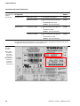
1
USER MANUAL VT250-57× Hardware Description Sense it! Connect it! Bus it! Solve it! All brand and product names are trademarks or registered trade marks of the owner concerned. Edition 06/2010 © Hans Turck GmbH, Muelheim an der Ruhr All rights reserved, including those of the translation. No part of this manual may be reproduced in any form (printed, photocopy, microfilm or any other process) or processed, duplicated or distributed by means of electronic systems without written permission of Hans Turck GmbH & Co. KG, Muelheim an der Ruhr. Subject to alterations without notice General safety instructions! Before starting the installation of automation components: Verify that the device is disconnected from the power supply. Ensure that devices cannot be accidentally restarted. Verify isolation from the supply. Earth and short circuit the device. Cover or enclose neighboring units that are live. Follow the engineering instructions of the device concerned. Only suitably qualified personnel in accordance with EN 50 110-1/-2 (VDE 0 105 Part 100) may work on this device/system. Before installation and before touching the device ensure that you are free of electrostatic charge. The functional earth (FE) must be connected to the protective earth (PE) or to the potential equalization. The system installer is responsible for implementing this connection. Connecting cables and signal lines should be installed so that inductive or capacitive interference do not impair the automation functions. Install automation devices and related operating elements in such a way that they are well protected against unintentional operation. Suitable safety hardware and software measures should be implemented for the I/O interface so that a line or wire breakage on the signal side does not result in undefined states in the automation devices. Ensure a reliable electrical isolation of the low voltage for the 24 volt supply. Only use power supply units complying with IEC 60 364-4-41 (VDE 0 100 Part 410) or HD 384.4.41 S2. Deviations of the power source from the nominal value must not exceed the tolerance limits given in the specifications, otherwise this may cause malfunction and dangerous operation. Emergency stop devices complying with IEC/EN 60 204-1 must be effective in all operating modes of the automation devices. Unlatching the emergency-stop devices must not cause restart. Devices that are designed for mounting in housings or control cabinets must only be operated and controlled after they have been installed with the housing closed. Desktop or portable units must only be operated and controlled in enclosed housings. Measures should be taken to ensure the proper restart of programs interrupted after a voltage dip or failure. This should not cause dangerous operating states even for a short time. If necessary, emergencystop devices should be implemented. Wherever faults in the automation system may cause damage to persons or property, external measures must be implemented to ensure a safe operating state in the event of a fault or malfunction (for example, by means of separate limit switches, mechanical interlocks etc.). The electrical installation must be carried out in accordance with the relevant regulations (e. g. with regard to cable cross sections, fuses, PE). All work relating to transport, installation, commissioning and maintenance must only be carried out by qualified personnel. (IEC 60 364 and HD 384 and national work safety regulations). All shrouds and doors must be kept closed during operation. D301191 - VT250 - Hardware 0610 I II D301191 - VT250 - Hardware 0610 Table of Contents About this manual Documentation concept....................................................................................................................0-2 Additional documentation ....................................................................................................................................................... 0-2 Description of symbols used .............................................................................................................0-3 Overview ...........................................................................................................................................0-4 Prescribed use ............................................................................................................................................................................... 0-4 Notes concerning planning /installation of this product .............................................................................................. 0-4 1 Safety Instructions General..............................................................................................................................................1-2 Electrical installation ........................................................................................................................1-3 Mounting ..........................................................................................................................................1-4 Repairs and maintenance..................................................................................................................1-5 Electrostatic discharge (ESD) ............................................................................................................1-6 Grounding methods.................................................................................................................................................................... 1-6 Instructions for the Lithium battery .................................................................................................1-7 FCC Statement...................................................................................................................................1-8 Electromagnetic Compatibility .........................................................................................................1-9 2 Scope of delivery Delivered parts .................................................................................................................................2-2 Optional parts/ accessory .................................................................................................................2-3 Type label and product identification ..............................................................................................2-4 3 Product description General..............................................................................................................................................3-3 Product properties ............................................................................................................................3-4 Display/Touch................................................................................................................................................................................ 3-4 Memory............................................................................................................................................................................................ 3-4 Service-button............................................................................................................................................................................... 3-4 Interfaces ......................................................................................................................................................................................... 3-4 Power supply ................................................................................................................................................................................. 3-4 Protection class ............................................................................................................................................................................. 3-5 Cooling ............................................................................................................................................................................................. 3-5 D301191 - VT250 - Hardware 0610 i Hardware VT250-57x ........................................................................................................................3-6 Front view ....................................................................................................................................................................................... 3-8 Rear view ......................................................................................................................................................................................... 3-8 Top view........................................................................................................................................................................................... 3-9 Bottom view .................................................................................................................................................................................3-10 TFT LCD display...............................................................................................................................3-11 (Re-)calibration of the touch screen ....................................................................................................................................3-11 Care and cleaning ......................................................................................................................................................................3-11 Power supply...................................................................................................................................3-13 Interfaces ........................................................................................................................................3-15 Field bus connection.................................................................................................................................................................3-15 Service-button ................................................................................................................................3-21 Replacing the Lithium battery ........................................................................................................3-22 SD/MMC card slot ............................................................................................................................3-23 Inserting the memory card .....................................................................................................................................................3-23 Removing the memory card...................................................................................................................................................3-23 Technical data .................................................................................................................................3-24 Display/Touch..............................................................................................................................................................................3-24 Controller.......................................................................................................................................................................................3-24 Interfaces .......................................................................................................................................................................................3-24 Power supply ...............................................................................................................................................................................3-24 General data .................................................................................................................................................................................3-25 Dimensions ..................................................................................................................................................................................3-25 CE directives and standards ............................................................................................................3-26 Electrical Safety ..........................................................................................................................................................................3-26 EMC standards.............................................................................................................................................................................3-26 Firmware download via SD/MMC-card............................................................................................3-27 FTP-access .......................................................................................................................................3-29 access data....................................................................................................................................................................................3-29 FTP-access via Windows-explorer ........................................................................................................................................3-29 CONFIG.CFG..................................................................................................................................................................................3-29 IP-address setting ...........................................................................................................................3-30 Addressing via IP Adress Tool ................................................................................................................................................3-30 ii D301191 - VT250 - Hardware 0610 4 Mounting instructions General..............................................................................................................................................4-2 System mounting to a sub frame or panel ........................................................................................4-3 Mounting clamps ......................................................................................................................................................................... 4-3 Ensuring the protection class IP65......................................................................................................................................... 4-3 Panel cut-out.................................................................................................................................................................................. 4-4 Mounting instructions ............................................................................................................................................................... 4-5 5 Index D301191 - VT250 - Hardware 0610 iii iv D301191 - VT250 - Hardware 0610 About this manual Documentation concept....................................................................................................................... 2 Additional documentation ........................................................................................................................................................... 2 Description of symbols used ................................................................................................................ 3 Overview .............................................................................................................................................. 4 Prescribed use ................................................................................................................................................................................... 4 Notes concerning planning /installation of this product .................................................................................................. 4 D301191 - VT250 - Hardware 0610 0-1 About this manual Documentation concept This manual contains the hardware description for the TURCK HMI product family. The operating system and the application software are not part of the description. The manual is part of the device and the instructions contained in this manual have always to be considered. Additional documentation D301189 "Getting Started - VT250-57P HMI PLC with PROFIBUS-DP" D301195 "Getting Started - VT250-57P HMI PLC with CANopen" D301218 "Getting Started - VT250-57x - Vizualisation of Step7®-projects“ 0-2 D301191 - VT250 - Hardware 0610 Description of symbols used Description of symbols used Warning This sign can be found next to all notes that indicate a source of hazards. This can refer to danger to personnel or damage to the system (hardware and software) and to the facility. This sign means for the operator: work with extreme caution. Attention This sign can be found next to all notes that indicate a potential source of hazards. This can refer to possible danger to personnel and damages to the system (hardware and software) and to the facility. Note This sign can be found next to all general notes that supply important information about one or more operating steps. These specific notes are intended to make operation easier and avoid unnecessary work due to incorrect operation. D301191 - VT250 - Hardware 0610 0-3 About this manual Overview Attention Please read this section carefully. Safety aspects cannot be left to chance when dealing with electrical equipment. This manual includes all information necessary for the prescribed use of TURCK HMIs. It has been specially conceived for personnel with the necessary qualifications. Prescribed use Warning The devices described in this manual must be used only in applications prescribed in this manual or in the respective technical descriptions, and only with certified components and devices from third party manufacturers. Appropriate transport, storage, deployment and mounting as well as careful operating and thorough maintenance guarantee the trouble-free and safe operation of these devices. Notes concerning planning /installation of this product Warning All respective safety measures and accident protection guidelines must be considered carefully and without exception. 0-4 D301191 - VT250 - Hardware 0610 1 Safety Instructions General................................................................................................................................................. 2 Electrical installation ........................................................................................................................... 3 Mounting ............................................................................................................................................. 4 Repairs and maintenance..................................................................................................................... 5 Electrostatic discharge (ESD) ............................................................................................................... 6 Grounding methods........................................................................................................................................................................ 6 Instructions for the Lithium battery .................................................................................................... 7 FCC Statement...................................................................................................................................... 8 Electromagnetic Compatibility ............................................................................................................ 9 D301191 - VT250 - Hardware 0610 1-1 Safety Instructions General Please read this section carefully and observe the instructions for your own safety and correct use of the device. Note This chapter contains safety instructions that are additional to the general safety instructions at the beginning of this manual (see General safety instructions!) as well as information on approval and interference suppression of your device. Observe the warnings and instructions on the device and in the manual. The VT250 has been built and tested in accordance to IEC/EN/UL/CSA 60950 and left the company in a perfectly safe condition. In order to maintain this condition and ensure safe operation, the user must observe the instructions and warnings contained in this manual. 1-2 D301191 - VT250 - Hardware 0610 Electrical installation 1 Electrical installation The device must be used in accordance with the instructions for use. The electrical installations in the room must correspond to the requirements of the local (countryspecific) regulations. Take care that there are no cables, particularly power cables, in areas where persons can trip over them. Do not use a power cable in sockets shared by a number of other power consumers. Do not use an extension cable. Don’t use injured or damaged power cords. Hints for DC power connection: – The DC power source should be able to be switched off and on via an isolating switch. – The VT250 is only completely disconnected from the DC main power source, when the DC power cord is disconnected either from the power source or the unit. Therefore, the DC power cord and its connectors must always remain easily accessible. Only devices and components which fulfill the requirements of an SELV circuit (safety extra low voltage) in accordance with EN60 950 may be connected to the interfaces of the system. The DC-input must fulfill SELV requirements of EN 60 950-1 standard. D301191 - VT250 - Hardware 0610 1-3 Safety Instructions Mounting Note Please read also chapter 4: Mounting instructions. Attention The device is designed for indoor use only. Do not place the device in direct sunlight, near heat sources or in a damp place. Make sure the device has adequate ventilation. All plugs on the connection cables must be screwed or locked to the housing. The VT250 is designed to be used only in vertical position with the interfaces downwards. The device generates heat during operation. Make sure it is adequately ventilated. Do not cover the air intake and exhaust openings of the device. 1-4 D301191 - VT250 - Hardware 0610 Repairs and maintenance Repairs and maintenance Repairs may only be carried out by qualified specialist personnel authorized by Hans Turck GmbH & Co. KG. Maintenance or repair on the open device may only be carried out by qualified personnel authorized by Hans Turck GmbH & Co. KG which is aware of with the associated dangers. Only approved original accessories (optional parts) approved by Hans Turck GmbH & Co. KG may be used. It must be assumed that safe operation is no longer possible, – if the device has visible damage or – if the device no longer functions. In these cases the device must be shut down and secured against unintentional operation. D301191 - VT250 - Hardware 0610 1-5 1 Safety Instructions Electrostatic discharge (ESD) A sudden discharge of electrostatic electricity can destroy static-sensitive devices or micro-circuitry. Proper packaging and grounding techniques are necessary prerequisites for avoiding damage. Always take the following precautions: 1 Transport printed circuit boards in static-safe containers such as boxes or bags. 2 Keep electrostatic sensitive parts in their containers until they arrive at a static-free station. 3 Always be properly grounded when touching a sensitive PCB, component, or assembly. 4 Store electrostatic-sensitive PCB’s in protective packaging or on conductive foam. Grounding methods Guard against electrostatic damage of the device by taking the following preventative steps: 1 Cover workstations with approved anti-static material. Provide a wrist strap connected to a work surface and properly grounded tools and equipment. 2 Use anti-static mats, heel straps, or air ionizers for added protection. 3 Handle electrostatic-sensitive components, PCB’s, and assemblies by the case or the edge of the board. 4 Avoid contact with pins, leads, or circuitry. 5 Turn off power and input signals before inserting and removing connectors or test equipment. 6 Keep the work area free of non-conductive materials such as ordinary plastic assembly aids and Styrofoam. 7 Use field service tools, such as cutters, screwdrivers, and vacuum cleaners that are conductive. 8 Always lay drives and PCB’s with the component-side down on the foam. 1-6 D301191 - VT250 - Hardware 0610 Instructions for the Lithium battery Instructions for the Lithium battery The ETX baseboard is equipped with a Lithium battery (CMOS battery). For replacing the Lithium battery, please observe the instructions described in Replacing the Lithium battery, page 3-22. Warning Danger of explosion when replaced with wrong type of battery. Replace the battery only with UL listed Lithium battery that has the same or equivalent type recommended by TURCK. Do not dispose of used CMOS batteries in domestic waste. Dispose of the battery according to the local regulations dealing with the disposal of these special materials (e. G. to the collecting points for disposal of batteries). D301191 - VT250 - Hardware 0610 1-7 1 Safety Instructions FCC Statement This equipment has been tested and found to comply with the limits for a Class A digital device, pursuant to Part 15 of the FCC Rules. These limits are designed to provide reasonable protection against harmful interference when the equipment is operated in commercial environment. This equipment generates, uses, and can radiate radio frequency energy and, if not installed and used in accordance with the instruction manual, may cause harmful interference to radio communications. Operation of this equipment in residential area is likely to cause harmful interference in which case the user will be required to correct the interference at his own expense. (English): This Class A digital apparatus complies with the Canadian ICES-003. (French): Cet appareil numérique de la classe A est conforme à la norme NMB-003 du Canada. 1-8 D301191 - VT250 - Hardware 0610 Electromagnetic Compatibility Electromagnetic Compatibility This product is intended only for use in industrial areas. T he most recent version of the EMC guidelines (EMC Directive 2004/108/EC) applies. If the user modifies and/or adds to the equipment (e.g. installation of add-on cards) the prerequisites for the CE conformity declaration may no longer apply. Warning This is a class A product. In domestic environment this product may cause radio interference in which case the user may be required to take adequate measures. D301191 - VT250 - Hardware 0610 1-9 1 Safety Instructions 1-10 D301191 - VT250 - Hardware 0610 2 Scope of delivery Delivered parts .................................................................................................................................... 2 Optional parts/ accessory .................................................................................................................... 3 Type label and product identification ................................................................................................. 4 D301191 - VT250 - Hardware 0610 2-1 Scope of delivery Delivered parts Table 1: Delivered parts Phoenix Power Plug Terminal CAN-connector (only with VT250-57C-×××) 8 × mounting clamp with threaded pins (hexagon socket) p Battery holder with Lithium battery 3.0 V for RTC, type: CR2032 2-2 D301191 - VT250 - Hardware 0610 Optional parts/ accessory Optional parts/ accessory This accessory can be ordered from Hans Turck GmbH & Co. KG 2 SD/MMC-card (2 GB) fieldbus accessories ((repeaters, etc..), see www.turck.com connection accessories (fieldbus cables, voltage cables etc.), , see www.turck.com D301191 - VT250 - Hardware 0610 2-3 Scope of delivery Type label and product identification Table 2:8 Type label and product identification Product Designation System configuration VT250-57P- xxx VT250-57P-L1-QVIS HMI with QVIS visualization 6828008 VT250-57P-L7-DPM HMI panel with QVIS and optional PLC – PROFIBUS-DP master – Modbus TCP master/slave 6828009 VT250-57C-L7-COM HMI panel with QVIS and optional PLC – CANopen master – Modbus TCP master/slave 6828005 VT250-57C-L7-DNM HMI panel with QVIS and optional PLC – DeviceNet™ master – Modbus TCP master/slave 6828006 VT250-57C-xxx Serial number The type label (product designation, serial number) and the configuration label (ordered system configuration) are located on the rear side of the device. Figure 1: Type label (example) A Type label: designation base device VT250-57P or VT250-57C B configuration label Device designation incl. licenses and firmware 2-4 A B D301191 - VT250 - Hardware 0610 3 Product description General................................................................................................................................................. 3 Product properties ............................................................................................................................... 4 Display/Touch.................................................................................................................................................................................... 4 Memory................................................................................................................................................................................................ 4 Service-button................................................................................................................................................................................... 4 Interfaces ............................................................................................................................................................................................. 4 Power supply ..................................................................................................................................................................................... 4 Protection class ................................................................................................................................................................................. 5 Cooling ................................................................................................................................................................................................. 5 Hardware VT250-57x ........................................................................................................................... 6 Front view ........................................................................................................................................................................................... 8 Rear view ............................................................................................................................................................................................. 8 – VT250-57P ....................................................................................................................................................................................... 8 – VT250-57C ....................................................................................................................................................................................... 9 Top view............................................................................................................................................................................................... 9 – VT250-57× ...................................................................................................................................................................................... 9 Bottom view .....................................................................................................................................................................................10 – VT250-57P .....................................................................................................................................................................................10 – VT250-57C .....................................................................................................................................................................................10 TFT LCD display.................................................................................................................................. 11 (Re-)calibration of the touch screen ........................................................................................................................................11 Care and cleaning ..........................................................................................................................................................................11 Power supply...................................................................................................................................... 13 Interfaces ........................................................................................................................................... 15 Field bus connection.....................................................................................................................................................................15 – PROFIBUS-DP (back side, VT250-57P-×××)....................................................................................................................... 15 – CAN (back side, VT250-57C-×××) .........................................................................................................................................16 – Ethernet I and Ethernet II (bottom side, both types of VT250) ..................................................................................17 – RS232/RS485 (COM) interface (bottom side, both types of VT250) .........................................................................18 – Bus termination for RS485 ......................................................................................................................................................19 – USB Device male connector (bottom side, both types of VT250) ............................................................................20 Service-button ................................................................................................................................... 21 Replacing the Lithium battery ........................................................................................................... 22 SD/MMC card slot ............................................................................................................................... 23 Inserting the memory card .........................................................................................................................................................23 Removing the memory card.......................................................................................................................................................23 Technical data .................................................................................................................................... 24 Display/Touch..................................................................................................................................................................................24 Controller...........................................................................................................................................................................................24 Interfaces ...........................................................................................................................................................................................24 Power supply ...................................................................................................................................................................................24 General data .....................................................................................................................................................................................25 Dimensions ......................................................................................................................................................................................25 D301191 - VT250 - Hardware 0610 3-1 3 Product description CE directives and standards ............................................................................................................... 26 Electrical Safety ..............................................................................................................................................................................26 EMC standards.................................................................................................................................................................................26 Firmware download via SD/MMC-card............................................................................................... 27 FTP-access .......................................................................................................................................... 29 access data........................................................................................................................................................................................29 FTP-access via Windows-explorer ............................................................................................................................................29 CONFIG.CFG......................................................................................................................................................................................29 IP-address setting .............................................................................................................................. 30 Addressing via IP Adress Tool ....................................................................................................................................................30 3-2 D301191 - VT250 - Hardware 0610 General General The VT250 is a Human-Machine-Interface (HMI) system designed for demanding industrial applications. VT250 is a workstation system with integrated touch screen display designed for: Installation in an instrument panel or other cabinets 3 Installation by VESA 75/100 compliant mounting system Note All versions are suitable for installation in an instrument panel or other cabinet. VT250s will be mounted in an instrument panel or other cabinets using the included mounting clamps. D301191 - VT250 - Hardware 0610 3-3 Product description Product properties The rugged design with an excellent mechanical stability marks the superior qualities of a computer suitable for the operation in harsh industrial environment. Display/Touch The VT250 system is equipped with a 5.7” display. In front of the display there is installed a touch screen, that also protects the display surface from dirt and scratches. Memory The VT250 accommodates a single computer board and an external accessible slot for SD/MMCcards. Table 3: Memory ROM 16 MB Flash RAM 32 MB SDRAM Permanent memory 16 kB SDRAM (battery buffered) Additional memory 1 x SD/MMC memory card, max. 2 GB Service-button The service-button is located on the rear side of the VT250. Interfaces 1 × PROFIBUS-DP SUB-D connector (VT250-57P-xxx), see page 3-15 1 × CAN-connector (VT250-57C-xxx), see page 3-16 2 × Ethernet (10/100 Mbps) 1 × serial COM (RS232/RS485), see page 3-17 1 × USB Device male connector (service interface only, see page 3-20) Power supply → see also Power supply, page 3-13 The VT250 is designed to be connected to a +24VDC power supply using the DC power terminal. Use the included DC-power supply terminal. In order to connect the system to an AC power supply can be ordered the optional external AC/ DC adapter. 3-4 D301191 - VT250 - Hardware 0610 Product properties Protection class Note The VT250s only comply with IP65 protection class at the front side, if the panel is fully mounted (see also Mounting instructions, page 4-5). Cooling The VT250 is a fanless system. The air openings, located on the sides of the device provide air circulation for the system interior cooling, in order to prevent overheating. Note When powering on the VT250, make sure that the air intake and exhaust openings are not obstructed. D301191 - VT250 - Hardware 0610 3-5 3 Product description Hardware VT250-57x Figure 2: Product view VT250-57C-xxx Bottom view Left Right Front view Left view Top view Rear view 90 3-6 D301191 - VT250 - Hardware 0610 Hardware VT250-57x Figure 3: Product view VT250-57P-xxx 3 Bottom view Left Right Front view Left view Top view Rear view D301191 - VT250 - Hardware 0610 3-7 Product description Front view Figure 4: Front view A Front plate B 5.7’’ TFT LCD (color) A B Rear view VT250-57P Figure 5: Rear view VT250-57P A B A air exhaust openings B Service-button, page 3-21 C label D SUB-D for PROFIBUS, page 3-15 E mounting clamps, page 4-3 C D E 3-8 D301191 - VT250 - Hardware 0610 Hardware VT250-57x VT250-57C Figure 6: Rear view VT250-57C A A air exhaust openings B Service-button, page 3-21 C label D CAN female connector, page 3-16 E mounting clamps, page 4-3 B C D E Top view VT250-57× Figure 7: Top view VT250-57× A SD/MMC card slot page 3-23 B battery slot, page 3-22 D301191 - VT250 - Hardware 0610 A B 3-9 3 Product description Bottom view VT250-57P Figure 8: Top view VT250-57P A B C D A USB Device male connector, page 3-20 B COM interface, page 3-18 C Ethernet I/ Ethernet II, page 3-17 D 24 VDC power supply, page 3-15 VT250-57C Figure 9: Top view VT250-57C A USB Device male connector, page 3-20 B COM interface, page 3-18 C Ethernet I/ Ethernet II, page 3-17 D 24 VDC powersupply, page 3-15 3-10 A B C D D301191 - VT250 - Hardware 0610 TFT LCD display TFT LCD display The VT250 provides a 5.7’’-size TFT display with corresponding resistive touch screen (glass-glass technology) The touch screen is USB connected. For technical specification of the built-in display refer to the section Technical data, page 3-24. 3 The display is equipped with a resistive touch screen. The surface of the display is also mechanically protected through the touch screen. The touch screen registers contacts of a finger or a pen and allows moving the mouse pointer. Use a stylus (not included) for best results. These functions can only be used under integration of the necessary software. You get the corresponding touch screen driver for your operating system, installed on your VT250 Attention Do not use a hard or a pointed object (like screw drivers) to operate the touch screen, since it can damage the touch screen surface. The front panel and the touch screen are covered by a plastic overlay and care should be taken when cleaning it (see Care and cleaning, page 3-11). (Re-)calibration of the touch screen The touch screen is calibrated, when the device is delivered. If a re-calibration should be necessary, due to malfunction of the touch screen for example, please observe the following steps: 1 Touch the touch screen when powering the device. →The device is automatically changing into the calibration-mode. 2 Now, touch the shown crosses one after the other exactly in their middle. Use a touch screen pen for example. Note The front panel and the touch screen are covered by a plastic overlay Do not use any pointed or sharp tools for operating it! 3 After the calibration, the devices changes back to the operation mode. Note In order to exit the calibration mode prematurely, execute a power reset at the device without touching the screen during the reset. The former calibration will be kept. Care and cleaning Note The front panel and the touch screen are covered by a plastic overlay and care should be taken when cleaning it. Mild detergent and water is recommended for cleaning. Use of strong solvents, which could attack paint or plastic, should be avoided. D301191 - VT250 - Hardware 0610 3-11 Product description The plastic overlay or the touch screen surface is subject to burning and scaring from direct heat sources such as cigarettes. The display front is sealed against dust, liquids, etc. The front surface of the touch screen is a flexible plastic foil, so care should be used to avoid using sharp objects such as knife, pen or pencil tips. Sharp objects can permanently damage the functionality of the touch screen. 3-12 D301191 - VT250 - Hardware 0610 Power supply Power supply The VT250 is delivered with the DC power plug terminal (3-pin, Phoenix Contact). For the DC connection prepare the connecting wires using the supplied Phoenix Contact plug terminal.. 3 Figure 10: 3-Pin Phoenix Contactconnector Note The length of the DC connecting wires may not exceed 10 m. Figure 11: Phoenix Contact connector (view from the wiring side) + = GND + = 24 VDC = PE Note The DC power source should be able to be switched off and on via an isolating switch. The VT250 is only completely disconnected from the DC main power source, when the DC power cord is disconnected either from the power source or the unit. Therefore, the DC power cord and its connectors must always remain easily accessible. Cable preparation and connection to power 1 Cut two isolated wires of the required length [AWG18 (Ø up to 1 mm2)] 2 Strip each end 5 to 7 mm. 3 Ensure that the DC power source is switched off via an isolating switch, in order to ensure that no power is flowing from the external power source during the connection procedure. 4 Loosen the three slotted pan head screws (that correspond to the marked location "+", "-" and "PE" of the DC plug terminal) far enough so that you can insert the end of the prepared wires. Note Connect the PE if necessary for your grounding system. 5 Insert the wires into the corresponding clamp of the Phoenix plug terminal. Make sure that you have the right polarity of the connection (refer to Figure 10: 3-Pin Phoenix Contact- connector). D301191 - VT250 - Hardware 0610 3-13 Product description 6 Fasten the screws to secure the wires into the clamps of the plug terminal. Note The second end of each wire will be prepared as required for the connection to the DC power supply. 7 Connect the other end of the DC power cable to the terminals of the 24V DC power source. Ensure that the power connections maintain the proper polarity. 8 Switch on the isolating switch in order to the apply voltage. 3-14 D301191 - VT250 - Hardware 0610 Interfaces Interfaces Field bus connection PROFIBUS-DP (back side, VT250-57P-×××) 3 The PROFIBUS-DP-connector is designed as a standard 9-pole SUB-D female connector: Figure 12: PROFIBUS-DPSUB-D female connector Table 4: Pin assignment of the SUB-D female connector v 1 6 5 9 1 = Schirm 2 = n.c. 3 = RD (Bus B) 4 = n.c. 5 = GND 6 = 5 VDC 7 = n.c. 8 = GN (Bus A) 9 = n.c. Pin-no. Signal Color 1 Shield shielding braid 2 not connected not connected - 3 Bus B DP-signal B RD 4 not connected not connected - 5 GND Data reference potential 6 5 VDC + 5 V DC for external bus termination 7 not connected not connected - 8 Bus A DP-signal A GN 9 not connected not connected - D301191 - VT250 - Hardware 0610 red green 3-15 Product description CAN (back side, VT250-57C-×××) The device provides a mounted CAN male connector. The additional female Open Style Connector is also delivered with the device: Figure 13: CAN-male connector Table 5: CANconnector, pin assignment 3-16 1 = BK (V ) 2 = BU (CAN L) 3 = Schirm 4 = WH (CAN H) 5 = RD (V +) 1 2 3 4 5 Pin-no. Signal Color 1 V- Ground reference (only used for DeviceNet node-supply) BK black 2 CAN_L Inverted data signal BU blue 3 Shield Shielding braid, not insulated 4 CAN_H Non-inverted data signal WH white 5 V+ Supply voltage, 24 V DC (only used for DeviceNet node-supply) RD red D301191 - VT250 - Hardware 0610 Interfaces Ethernet I and Ethernet II (bottom side, both types of VT250) These interface connectors (see also Figure 5: Rear view VT250-57P and Figure 6: Rear view VT25057C) are provided as auto-crossing RJ45-sockets with integrated LEDs Figure 14: Ethernet I and Ethernet II v 87654321 Table 6: RJ45, pin assignment 1 = YE 2 = OG 3 = WH 4 = n.c. 5 = n.c. 6 = BU 7 = n.c. 8 = n.c. 3 (TX +) (TX ) (RX +) (RX ) Pin-no. Signal Color 1 TX+ Transmit data + YE yellow 2 TX– Transmit data – OG orange 3 RX+ Receive data + WH white 4 not connected - - 5 not connected - - 6 RX– BU blue 7 not connected - - 8 not connected - - Receive data – Ethernet Port properties: Integrated switch Auto-crossing Data transfer rate: 10/100 Mbps Protocols: PROFINET, EtherNet/IP™, Modbus TCP Ethernet LED-states Table 7: Ethernet LEDstates Left LED Link Right LED Activity off no link off no data exchange green Link active yellow data exchange D301191 - VT250 - Hardware 0610 3-17 Product description RS232/RS485 (COM) interface (bottom side, both types of VT250) The VT250 COM (RS232/RS485) interface is a serial interface with a special pin assignment. Figure 15: COM interface Table 8: COM interface at the VT250 Assignment Pinno. at the VT250 5 9 1 6 1 = RX/TX (B) 2 = RxD 3 = TxD 4 = n.c. 5 = GND 6 = RX/TX+ (A) 7 = RTS 8 = CTS 9 = 3,3 VDC can be used for RS232 [COM1] RS485 RS232 RS232 RS232 RS485 RS232 RS232 RS485 [COM2] standard assignment for RS232 (for reference) X DCD 1 RX/TX- (B) 2 RxD X RxD 3 TxD X TxD 4 not connected 5 GND 6 RX/TX+ (A) 7 RTS X RTS 8 CTS X CTS 9 3.3 VDC DTR X GND X DRS RI Attention Please do not use a standard null modem cable for the connection to the RS232/485 interface and observe the following special pinning instructions! 3-18 D301191 - VT250 - Hardware 0610 Interfaces Wiring for RS232 and RS485 Table 9: COM-interface, pin assignment RS232-connection VT250 DTE Pin-no. Signal Signal 5 GND GND 2 RxD RxD 3 TxD TxD 7 RTS RTS 8 CTS CTS 4 6 1 9 3 DTR Reserved for RS485operation, not to be used in RS232-operation Do not connect! DSR DCD RI RS485-connection Pin-no. Signal Signal 5 2 3 Do not connect in RS485-operation! 7 8 4 6 1 120 Ω 9 RX/TX+ (A) RX/TX+ (A) RX/TX- (B) RX/TX- (B) 120 Ω Do not connect in RS485-operation! Bus termination for RS485 For all standard applications use a 120 Ω-bus termination between A and B at both ends of the RS485-communication line. D301191 - VT250 - Hardware 0610 3-19 Product description USB Device male connector (bottom side, both types of VT250) The system is equipped with one USB-Device connector, type B (see also Figure 5: Rear view VT25057P and Figure 6: Rear view VT250-57C). Figure 16: USB Device female connector Type B 1 2 4 3 1 2 3 4 = RD (Vcc) +5 V = WH (D ) = GN (D +) = BK (GND) Note This interface is only used as a service interface (no for customers). 3-20 D301191 - VT250 - Hardware 0610 Service-button Service-button The service-button is only used during the device start-up to switch the device to the bootloader mode. This mode is only important for service cases. 3 D301191 - VT250 - Hardware 0610 3-21 Product description Replacing the Lithium battery The VT250 system is equipped with a Lithium battery. This battery is located in a battery holder on the top side of the device (see Figure 17: Battery holder). Figure 17: Battery holder To replace this battery, please proceed as follows: 1 Pull the battery holder from the case using a coin or any other flat object. 2 Press the battery out off the holder 3 The new battery has to be placed into the battery holder with the positive (+) battery terminal face-up. 4 Make sure that you insert the battery correctly. The plus pole must be on top, which means, the battery plus pole has to be on the same side as the "+"-marked side (see Figure 18: Battery holder, inserting the battery) of the battery holder! Figure 18: Battery holder, inserting the battery 5 Insert the battery holder vertically to the top side into the battery slot in the device case. The "+"marked side of the battery holder must be directed to the rear side of the device. The lithium battery must be replaced with an identical battery (Lithium battery 3.0 V for RTC, type: CR2032) or a battery type recommended by Hans Turck GmbH & Co. KG. Warning Danger of explosion when replaced with wrong type of battery. Replace the battery only with an UL-listed Lithium battery that has the same or equivalent type recommended by Hans Turck GmbH & Co. KG. Do not dispose of used CMOS batteries in domestic waste. Dispose of the battery according to the local regulations dealing with the disposal of these special materials (e. g. to the collecting points for disposal of batteries). 3-22 D301191 - VT250 - Hardware 0610 SD/MMC card slot SD/MMC card slot The VT250 is equipped with a SD/MMC card slot. This slot is located on the top side of the device (see Top view) next to the battery slot. The SD/MMC card is not delivered with the system. It can be ordered separately from TURCK. Only standard SD cards are supported, no SDHC cards.-cards! Note Before installing or removing the SD/MMC card, the VT250 must be powered down and disconnected from the power source. Inserting the memory card Insert the SD/MMC card vertically from above to the card slot until it locks into place with a click. The card contacts have to be directed to the device’s front side (to the display). Note Inserting the card in the wrong direction could damage the device. Be sure the card is oriented correctly (card contacts directed to the display). Removing the memory card Push the memory card in until you hear a click, then slowly release it. The card will pop up and can be taken out. D301191 - VT250 - Hardware 0610 3-23 3 Product description Technical data Display/Touch Table 10: Technical data display/ touch screen Display TFT LCD (color-display) Active screen area 5,7'' (approx. 118 × 89 mm) Resolution (pixels) 320 x 240 (240 * 320 with portrait configuration) Number of usable colors 65536 colors Touch resistive Controller Table 11: Technical data controller Processor ARM9, 32 bit, 200 MHz ROM memory 16 MB Flash RAM memory 32 MB SDRAM Permanent memory 16 kB SDRAM (battery buffered) Additional memory 1 x SD/MMC Memory Card, no SDHC Real time clock yes Operating system rcX Interfaces Table 12: Technical data interfaces Ethernet 10/100 Mbps, double (integrated switch) Protocols PROFINET, EtherNet/IP™, Modbus TCP Field bus – PROFIBUS-DP (VT250-57P-×××) – CAN/ DeviceNet™ (VT250-57C-×××) USB Device male connector, type B Serial RS232/RS485 Power supply Table 13: Technical data power supply 3-24 Rated value 24 VDC reverse-polarity protected, 0.35 A maximum, according to EN 61131-2 Admissible voltage range 20.4 ... 30 VDC Lithium battery 3,0 V for RTC, type: CR2032, UL-listed D301191 - VT250 - Hardware 0610 Technical data General data Table 14: General technical data Operating ambient conditions 0…50 °C, 10…90 % relative humidity, non condensing Storage ambient conditions -20…60 °C, 10…95 % relative humidity, non condensing Approvals CE, cULus Protection class IP 65 according IEC 60529 on front, IP20 on rear 3 Dimensions Table 15: Dimensions Front (W x H x D) 212 x 156 x 50 mm Cut-out (W x H) 198 x 142 mm Weight approx. 0,7 kg D301191 - VT250 - Hardware 0610 3-25 Product description CE directives and standards CE directives Table 16: CE directives CE directives Low Voltage Directive (Electrical Safety) General Product Safety Directive (GPSD) 2001/95/EC EMC Directive Low Voltage Directive (LVD) 2006/95/EC Electrical Safety Table 17: Electrical Safety Electrical Safety Standards EUROPE Information technology equipment - Safety - Part 1: General requirements EN 60950-1: 2006 2006 USA / Canada UL 60950-1:2006 cULus Listed CB Scheme CB Certification EMC standards Table 18: EMC standards 3-26 EMC Standards EN 61000-3-2:2006 Limits - Limits for harmonic current emissions (equipment input current ≤ 16 A per phase) EN 61000-3-3:2006 Limitation of voltage changes, voltage fluctuations and flicker in public low-voltage supply systems, for equipment with rated current ≤ 16 per phase and not subjected to conditional connection EUROPE Generic emission standard for industrial environments (Emission): EN 61000-6-4:2007 Generic standards - Immunity for industrial environments (Immunity): EN 61000-6-2:2005 USA FCC 47 CFR Part 15, Class A Canada ICES-003, Class A D301191 - VT250 - Hardware 0610 Firmware download via SD/MMC-card Firmware download via SD/MMC-card For a firmware download from the SD/MMC card, please follow these steps: 1 Delete all data from the card. 2 Copy the files of the respective image onto the card. 3 Figure 19: Example for an image 3 Disconnect the VT250. 4 Insert the card into the card-slot. The card contacts have to be directed to the touch screen. 5 Power the VT250. POWER LED Figure 20: LEDs SYS LED 6 Monitor the LEDs on the rear side of the device. They are placed on the device's main board and can be seen through the air exhaust openings. 7 Do not disconnect the VT250. 8 The update procedure has been completed, when the "SYS" LED (2nd LED from the left) flashes and shows the following behavior: ON - ON - OFF, ON - ON - OFF, etc. 9 Now, disconnect the VT250 again. 10 Remove the card. 11 Again, power the VT250. 12 The devices starts with the new firmware. 13 Recalibrate the device, if necessary. D301191 - VT250 - Hardware 0610 3-27 Product description 14 The firmware-version is shown in the display. Figure 21: Display of the firmware-version 3-28 D301191 - VT250 - Hardware 0610 FTP-access FTP-access access data Please set up the FTP-access as follows: IP-address: IP-address of the VT250 (Default: 192.168.1.254) User: netX Password: netX 3 FTP-access via Windows-explorer Copy the following line into the Windows®-Explorer address field: ftp://netX:netX:@192.168.1.254/ and confirm it with "Enter". Figure 22: FTP-access via Windows®explorer CONFIG.CFG The system file CONFIG.CFG contains all settings concerning the device-configuration (calibration, etc.). One deleted, the touch screen has to be recalibrated (see also (page 3-11: (Re-)calibration of the touch screen). D301191 - VT250 - Hardware 0610 3-29 Product description IP-address setting Default setting: IP-address: 192.168.1.254 Netmask: 255.255.255.0 Gateway: 192.168.1.1 Addressing via IP Adress Tool The TURCK IP Adress Tool can be used for reading out the IP settings, the device name as well as the firmware version. It also helps to adapt the IP settings to the respective application. Figure 23: IP Adress Tool Note The online help in the TURCK IP Adress Tool contains more detailed information about the program's function. 3-30 D301191 - VT250 - Hardware 0610 4 Mounting instructions General................................................................................................................................................. 2 System mounting to a sub frame or panel ........................................................................................... 3 Mounting clamps ............................................................................................................................................................................. 3 Ensuring the protection class IP65............................................................................................................................................. 3 Panel cut-out...................................................................................................................................................................................... 4 Mounting instructions ................................................................................................................................................................... 5 D301191 - VT250 - Hardware 0610 4-1 Mounting instructions General Attention The device is designed for indoor use only. 4-2 D301191 - VT250 - Hardware 0610 System mounting to a sub frame or panel System mounting to a sub frame or panel Mounting clamps The VT250 is delivered with mounting clamps and threaded pins in order to mount the system to a sub frame or panel The mounting clamps with threaded pins (supplied), allow the easy and fast mounting of the VT250 into an instrument panel or wall panel. Figure 24: Mounting clamps incl. threaded pins delivered with the VT250 Ensuring the protection class IP65 Attention In order to ensure protection class IP65 against dust and water at the front sealing, mount the VT250 on a non-textured surface. Before you install the system into a panel or a sub frame for industrial cabinet, verify the perfect condition of the seal at the rear of the front plate. The seal has to be in place without injury/defects and dirt. Figure 25: VT250 A seal to ensure IP65 A D301191 - VT250 - Hardware 0610 4-3 Mounting instructions Panel cut-out Figure 26: Panel cut-out Dimensions of the VT250 Note When installing the VT250 into a panel or a sub frame for industrial cabinet, leave enough free space on the rear top side of the system in order to have access to install or remove the SD/MMCcard and/or the battery. 4-4 D301191 - VT250 - Hardware 0610 System mounting to a sub frame or panel Mounting instructions Table 19: Dimensions for Requirements for mounting the Rear side enclosure (W × H × D) VT250 into a sub frame/panel Cut-out for mounting into a panel 196 × 140 × 50 [mm] 7,72 × 5,51 × 1,97 [inch] 198 ± 1 × 142 ± 1 [mm] 7,80 (± 0,4) × 5,60 (± 0,4) [inch] Requirements for mounting Metal mounting panel thickness 2 - 5 mm [mm] 0,08 - 0,20 [inch] Used clamps with threaded pins 8 Required tool hex key, 2 mm Maximum torque 0,15 Nm Mounting position Ensure the vertical and horizontal alignment of the system To mount the system to a sub frame or to a panel, follow these steps: 1 Depending on the dimension of the display enclosure of your system, cut a hole in the panel/sub frame 2 The panel where you intend to attach the system must be accessible from both front and rear side 3 The system must be turned off and disconnected from the power source and peripherals 4 Insert the system into the panel cut-out from the panel/sub frame front 5 In order to ensure the protection class IP65 on the front side in the installed condition, the contact surface with the seal must be clean and flush 6 Ensure the vertical and horizontal alignment of the system 7 Fasten the VT250 from the rear using the mounting clamps 8 Hook each of the 8 mounting clamps from the rear side of the panel into the corresponding recesses in the enclosure. Use one clamp on the left and right side of the device and 3 on the top as well as on the bottom side of the device. Note Please observe: IP65 can only be guaranteed if all 8 mounting clamps are used for mounting the VT250 9 The VT250 must be attached firmly with the threaded pins. Tighten the pins using a 2 mm hex key with a maximum torque of 0,15 Nm. D301191 - VT250 - Hardware 0610 4-5 Mounting instructions 4-6 D301191 - VT250 - Hardware 0610 5 Index A P accessory ........................................................................ 2-3 power supply .................................................................. 3-4 PROFIBUS-DP ................................................................ 3-15 C calibration .................................................................... 3-11 CAN ............................................................................... 3-16 CE directives and standards ......................................... 3-26 COM interface .............................................................. 3-18 CONFIG.CFG ................................................................. 3-29 cooling ............................................................................ 3-5 R RS232/RS485 ................................................................. 3-18 S safety instructions .......................................................... 1-1 SD/MMC ........................................................................ 3-23 service-button ................................................................ 3-4 D DC-voltage supply ....................................................... 3-13 delivered parts ............................................................... 2-2 display ............................................................................ 3-4 E Electromagnetic Compatibility ...................................... 1-9 ESD .................................................................................. 1-6 Ethernet I and Ethernet II ............................................. 3-17 T technical data ............................................................... 3-24 TFT LCD display ............................................................ 3-11 touch screen ................................................................... 3-4 – care and cleaning ...................................................... 3-11 type label ........................................................................ 2-4 U USB-Device ................................................................... 3-20 F firmware download ...................................................... 3-27 FTP ................................................................................ 3-29 W Windows®-Explorer ...................................................... 3-29 H hardware ........................................................................ 3-6 I image ............................................................................ 3-27 indoor use ....................................................................... 4-2 interfaces ........................................................................ 3-4 IP Adress Tool ............................................................... 3-30 IP65 ................................................................................. 4-3 IP-address ..................................................................... 3-30 L Lithium battery ..................................................... 1-7, 3-22 M memory .......................................................................... 3-4 memory card ................................................................ 3-23 mounting ........................................................................ 4-1 – mounting clamps 4-3 – mounting instructions 4-5 O optional parts ................................................................. 2-3 D301191 - VT250 - Hardware 0610 5-1 Index 5-2 D301191 - VT250 - Hardware 0610 Hans Turck GmbH & Co. KG 45472 Mülheim an der Ruhr Germany Witzlebenstraße 7 Tel. +49 (0) 208 4952-0 Fax +49 (0) 208 4952-264 E-Mail [email protected] Internet www.turck.com D301191 0610 www.turck.com