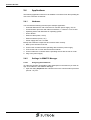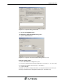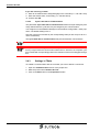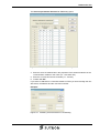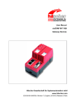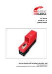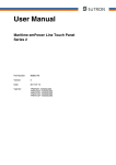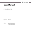
1
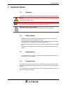
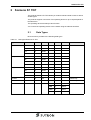
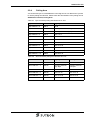
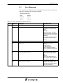
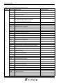
User Manual
Connection to Siemens S7 TCP
Part Number:
80 860.678
Version:
2
Date:
2008-02-01
Valid for:
TSwin .net 4.2
Version
1
2
Date
2005-11-18
2006-02-01
Modifications
First edition
New layout, protocol parameters note added, protocol parameter „Offline operation“ added
This manual, including all illustrations contained herein, is copyright protected. Use of this manual by any third
party in departure from the copyright provision is forbidden. No part of this manual may be reproduced, translated or electronically or photographically archived or altered without the express written consent from Sütron
electronic GmbH. Violations shall be cause for damage liability.
Sütron electronic reserves the right to make any changes that contribute to technical improvement.
Overall Table of Contents
Overall Table of Contents
1
2
Important Notes ....................................................................................................... 1-1
1.1
Symbols .................................................................................................... 1-1
1.2
Safety Notes ............................................................................................. 1-1
1.3
Intended Use............................................................................................. 1-1
1.4
Target Group............................................................................................. 1-1
Siemens S7 TCP ..................................................................................................... 2-1
2.1
Data Types................................................................................................ 2-1
2.2
Programming ............................................................................................ 2-2
2.2.1
A
Protocol Parameters ............................................................................ 2-2
2.2.1.1
Maximum Waiting Time For Response.......................................................................2-2
2.2.1.2
Delay until Connection Set-Up....................................................................................2-2
2.2.1.3
Offline Operation.........................................................................................................2-2
2.2.1.4
Connections................................................................................................................2-2
2.2.2
Input Syntax ......................................................................................... 2-4
2.2.3
Status Messages ................................................................................. 2-4
2.2.4
Polling Area ......................................................................................... 2-5
2.2.5
Physical Connection ............................................................................ 2-6
2.2.5.1
Pin Assignment...........................................................................................................2-6
2.2.5.2
Cable ..........................................................................................................................2-6
2.3
Error Messages......................................................................................... 2-7
2.4
Applications............................................................................................. 2-10
2.4.1
Hardware ........................................................................................... 2-10
2.4.2
Settings in SIMATIC Manager ........................................................... 2-10
2.4.2.1
Assigning the IP Address..........................................................................................2-10
2.4.2.2
Cycle Load due to Communication...........................................................................2-12
2.4.3
Settings in TSwin ............................................................................... 2-12
Index ........................................................................................................................A-1
i
Overall Table of Contents
ii
Important Notes
1
Important Notes
1.1
Symbols
The symbols in this manual are used to draw your attention on notes and dangers.
Danger
This symbol is used to refer to instructions which, if ignored or not carefully followed
could result in personal injury.
Note
This symbol indicates application tips or supplementary notes.
Reference to source of information
This symbol refers to detailed sources of information on the current topic.
1.2
Safety Notes
–
Read this manual carefully before using the software. Keep this manual in a
place where it is always accessible to all users.
–
The user manual, in particular the safety notes, must be observed by all personnel working with the software and the programmed device.
–
Observe the accident prevention rules and regulations that apply to the operating
site.
–
Installation and operation must only be carried out by qualified and trained personnel.
1.3
–
Intended Use
The software has to be used for programming operating devices exclusively. Every other use is not permitted.
1.4
Target Group
All configuration and programming work in connection with the automation system
must be performed by trained personnel only (e.g. qualified electricians, electrical engineers).
The configuration and programming personnel must be familiar with the safety concepts of automation technology.
1-1
Important Notes
1-2
Siemens S7 TCP
2
Siemens S7 TCP
The protocol Siemens S7 TCP allows you random read and write access to almost
all data types.
The protocol supports connection of an operating device to up to 16 participants at
the same time.
The operating device has always client function.
You connect the operating device to the network using the ethernet interface.
2.1
Data Types
Direct access is possible to the following data types.
Table 2-1
Data types Siemens S7 TCP
Type
Mnemonik
From
To
Input
E
0.0
16383.7
EB
0
16383
EW
0
16382
ED
0
16380
A
0.0
16383.7
AB
0
16383
AW
0
16382
AD
0
16380
M
0.0
16383.7
MB
0
16383
MW
0
16382
MD
0
16380
Counter
Z
0
512
Read Only
Timer
T
0
512
Read Only
Data Block
DB
0
8192
Output
Flag
From
To
Access
Read/Write
DBX
0.0
65535.7
DBB
0
65535
DBW
0
65534
DBD
0
65532
Read/Write
2-1
Siemens S7 TCP
2.2
Programming
2.2.1
Protocol Parameters
2.2.1.1
Maximum Waiting Time For Response
This parameter specifies how long the operating device waits for a response from the
controller.
Table 2-2
Maximum waiting time for response
Configurable Values
Default Value
0 s to 10000 s
10 s
2.2.1.2
Delay until Connection Set-Up
This parameter specifies the waiting time after which the operating device starts the
communication.
Table 2-3
Delay until connection set-up
Configurable Values
Default Value
0 s to 255 s
5s
2.2.1.3
Offline Operation
Check the Offline operation check box to write communication errors to the message
buffer without reboot of the project.
If the check box is not checked the communication error is displayed at the operating
devices display and afterwards the project is rebooted.
Table 2-4
Offline operation
Configurable Values
Default Value
OFF
X
ON
2.2.1.4
Connections
The operating device supports 16 connections at a time.
The connections list consists of 16 lines for the connections an 4 columns for the connection parameters.
Table 2-5
2-2
Connections, Siemens S7 TCP
Column
Meaning
Default
Value
Connection
Connection Number
1 to 16
IP address of controller
Address of the communication interface
0.0.0.0
Slot number
Number of the slot, where the module is
put on
0
Rack number
Rack number of the controller
0
Siemens S7 TCP
The number of MPI participants depends on the S7 CPU that is used.
Follow the respective operating instructions of the control to this.
2-3
Siemens S7 TCP
2.2.2
Input Syntax
The following image illustrates the structure of the input syntax for variables in the
programming software.
Z
Number
T
EB
EW
ED
AB
AW
AD
MB
MW
MD
E
Number
.
A
M
DB
Number
DBX
DBB
DBW
DBD
Figure 2-1
Syntax diagram
2.2.3
Status Messages
You have to assign a byte or word address for the parallel message system in the
flag area or in a data block (MB. MW, DBB or DBW).
Example:
Table 2-6
2-4
Parallel message system Siemens S7 TCP
Word address
Reference
High Byte
Low Byte
Word address + 0
MW 10
Messages 9 to 15
Messages 0 to 8
Word address + 1
MW 12
Messages 24 to 31
Messages 16 to 23
Word address + 2
MW 14
Messages 40 to 47
Messages 32 to 39
Siemens S7 TCP
2.2.4
Polling Area
You should use byte or word addresses in the flag area or in a data block if you like
to use the polling area function. Please enter the start address of the polling area in
Additional Functions, Polling Area.
Table 2-7
Byte accessed polling area Siemens S7 TCP
Byte address
Reference
High Byte
Byte address + 0
MB 12
WCB
Byte address + 1
MB 13
Message Channel Low Byte
Byte address + 2
MB 14
Message Channel High Byte
Byte address + 3
MB 15
LED 1 to 4
Byte address + 4
MB 16
LED 5 to 8
Byte address + 5
MB 17
LED 9 to 12
Byte address + 6
MB 18
LED 13 to 16
Byte address + 7
MB 19
LED 17 to 20
Byte address + 8
MB 20
LED 21 to 24
Byte address + 9
MB 21
LED 25 to 28
Byte address + 10
MB 22
LED 29 to 32
Table 2-8
Word accessed polling area Siemens S7 TCP
Word address
Reference
High Byte
Low Byte
Word address + 0
MW 20
WCB
Reserved
Word address + 2
MW 22
Message Channel
High Byte
Message Channel
Low Byte
Word address + 4
MW 24
LED 1 to 4
LED 5 to 8
Word address + 6
MW 26
LED 9 to 12
LED 13 to 16
Word address + 8
MW 28
LED 17 to 20
LED 21 to 24
Word address + 10
MW 30
LED 25 to 28
LED 29 to 32
2-5
Siemens S7 TCP
2.2.5
Physical Connection
The operating devices are connected to the network via the ethernet interface.
2.2.5.1
Pin Assignment
Connector in the operating device: RJ45 female connector.
Table 2-9
Assignment of the Ethernet interface
Pin
Designation
Function
1
Tx+
Transmitted Data, Positive Polarity
2
Tx-
Transmitted Data, Negative Polarity
3
Rx+
Received Data, Positive Polarity
4
n.c.
Not Connected
5
n.c.
Not Connected
6
Rx-
Received Data, Negative Polarity
7
n.c.
Not Connected
8
n.c.
Not Connected
2.2.5.2
Cable
A twisted pair cable of the category 5 (CAT 5) type must be used. The maximum cable length is 100 m (328.084 feet).
See the IEEE 802.3 standard for further information.
2-6
Siemens S7 TCP
2.3
Error Messages
Error messages are displayed on the operating device along with a code and subcode. Error messages are composed as follows:
Communication Error
Table 2-10
Code
Code
XXXXX
Subcode
XXXXX
Retries
XXXXX
Error messages for Siemens S7 TCP
Subcode
10
Error Type
Possible Cause
Connection errors
1
Timeout
Requested controller not
available or no longer available.
Remidy:
Generate further read and
write commands, to reset the
connection by the driver automatically.
Possibly encrease the value
for "Delay until connection
set-up".
4
Timeout
No response from control
5
General error
Netword not running.
Remidy:
Install TCP/IP.
Install Winsocket.
Check settings for polling.
area or parallel message system.
6
Target controller not found
Wrong rack or slot number.
No free connection for this
slot.
Remidy:
Check the configuration of
the communication module in
the SIMATIC Manager.
99
Invalid reference number
Possibly the variables list
contains a connection number that is not defined in the
protocol parameters.
2-7
Siemens S7 TCP
Table 2-10
Code
Error messages for Siemens S7 TCP
Subcode
20
2-8
Error Type
TCP socket errors
10004
Interrupted system call
10013
Permission denied
10014
Bad address
10022
1. Other function must be called before
2. Socket already assigned to address
3. Socket not assigned to address
10024
Missing resources (files, queues)
10035
Operation would block
10036
Operation now in progress
10037
Operation already in progress
10038
Socket operation on non-socket
10039
Destination address required
10040
Message too long
10042
Bad protocol option
10043
Protocol not supported
10044
Socket type not supported
10045
Operation not supported on socket
10046
Protocol family not supported
10047
Address family not supported by protocol family
10048
Address already in use
10049
Can't assign requested address
10050
Network is down
10051
Network is unreachable
10052
Net dropped connection or reset
10053
Software caused connection abort
10054
Connection reset by peer
10055
No buffer space available
10056
Socket is already connected
10057
Socket is not connected
10058
Can't send after socket shutdown
10060
Connection timed out
10061
Connection refused
10065
No Route to Host
10091
Network SubSystem is unavailable
10092
WINSOCK DLL Version out of range
Possible Cause
Siemens S7 TCP
Table 2-10
Error messages for Siemens S7 TCP
Code
Subcode
Error Type
20
10093
Successful WSASTARTUP not yet performed
11001
Host not found
11002
Non-Authoritative Host not found
11003
Non-Recoverable errors: FORMERR, REFUSED,
NOTIMP
11004
Valid name, no data record of requested type
30
Possible Cause
Data errors
2
Error on accessing data block
Data block is not present or
address is outside the data
block range
9
Value too large
Wrong value for
counter (<=999) or
Timer (<=9990000 ms).
10
Wrong data type
Data type is not supported.
Remidy:
Check the variables list
40
Hardware errors
8
Memory error
Cannot allocate memory area
for data.
Possibly the operating device
is faulty.
Remidy:
Check the application size.
Send the operating device to
our service.
2-9
Siemens S7 TCP
2.4
Applications
The following application shows how to establish a connection from the operating device to the controller via ethernet.
2.4.1
Hardware
You will need the following to build-up the example application:
–
Controller Siemens S7 300 or Siemens S7 400 with power supply, rail, etc.
–
Communication processor with ethernet interface, i.e. CP343-1 IT for S3 300
–
Operating device with Windows CE operating system
–
Hub or Router
–
Ethernet cable (Patch, CAT5)
–
Ethernet network (server, etc.)
–
Power supply 230 VAC / 24 VDC
Buid-up the hardware components and connect them correctly.
1. Buid-up the controller of the rail.
2. Connect the controller and the operating device with the power supply.
3. Connect the hub or router with the ethernet network.
4. Connect either the controller and the operating device with the hub or router.
5. Plug-in the power supply.
2.4.2
Settings in SIMATIC Manager
2.4.2.1
Assigning the IP Address
To make the controller accessible to other participants in the ethernet you must assign an IP address in the SIMATIC Manager.
1. Open the dialog Properties with a double click on the communication processor
(CP343-1 IT) icon.
2-10
Siemens S7 TCP
Figure 2-2
Properties dialog, General tab
2. Click on the Properties button..
The Properties - Ethernet interface dialog opens.
3. Open the Parameters tab.
Figure 2-3
Properties - Ethernet interface dialog, Parameters tab
If you are using a router:
4. Select Use router in the Netgateway area.
5. Enter an IP address that is assigned tightly to the controller (i.e.: 192.168.0.100).
6. Enter the IP address of the router (i.e.: 192.168.0.1).
7. Confirm with OK.
In addition you have to configure the router in a way that makes the controller permanently reachable with the assigned IP address (i.e.: 192.168.0.100).
2-11
Siemens S7 TCP
If you are not using a router:
8. Enter an IP address that is assigned tightly to the controller (i.e.: 192.168.0.100).
9. Enter the subnet mask, if necessary (i.e.: 255.255.255.0).
10. Confirm with OK.
2.4.2.2
Cycle Load due to Communication
The parameter Cycle load due to communication defines as a percentage by how
many milliseconds the cycle time may be charged by the communication.
You assign this in the SIMATIC Manager in the hardware configuration / CPU properties. The default setting is 20 %.
Here the cycle time encreases by the corresponding value (at 100 ms up to 20 ms =
120 ms maximum).
The Cycle load due to communication may amount between 10% and 50%.
Make sure that you don't exceed the cycle supervision time!
For cycle times in the range of 1 ms to 50 ms you can accelerate the screen build-up
time by a higher allowed communication load enormus. However, the complete cycle
time is extended correspondingly and so the reactions of the control sluggish through
this.
2.4.3
Settings in TSwin
To enable a communication with the controller you have to define a connection.
1. Open the Communication branch of the project tree.
2. Mark the protocol item Siemens S7 TCP.
3. Click on the Edit button in the Properties window.
2-12
Siemens S7 TCP
The Protocol parameters Siemens S7 TCP dialog opens.
Figure 2-4
Protocol parameters Siemens S7 TCP dialog
4. Enter the same IP address like in the properties of the ethernet interface of the
communication module or the router (i.e.: 192.168.0.100).
5. Enter the concrete slot and rack number (i.e.: 2 and 0).
6. Confirm with OK.
If you enter an address for a controller variable in TSwin you have to assign the variable name, the address and the connection number.
Example:
Figure 2-5
Variable, protocol Siemens S7 TCP dialog
2-13
Siemens S7 TCP
2-14
Index
A Index
C
Cable
Ethernet .................................................... 2-6
D
Data Types
Siemens S7 TCP ...................................... 2-1
E
Error messages
Siemens S7 TCP ...................................... 2-7
I
Important notes ................................................. 1-1
Intended use ..................................................... 1-1
P
Pin assignment
Ethernet .................................................... 2-6
Protocol parameters
Siemens S7 TCP ...................................... 2-2
S
Safety notes ...................................................... 1-1
Siemens S7 TCP .............................................. 2-1
Symbols ............................................................ 1-1
Syntax diagram
Siemens S7 TCP ...................................... 2-4
T
Target group ..................................................... 1-1
A-1
Index
A-2
Sütron electronic GmbH
Kurze Straße 29
D-70794 Filderstadt
Phone: 0049 711 / 77098-0
Fax:
0049 711 / 77098-60
E-Mail: [email protected]
Internet: www.suetron.com