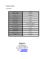
1
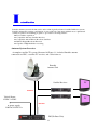
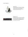
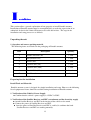
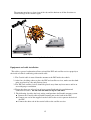
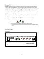
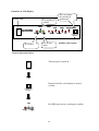
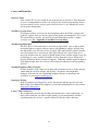
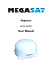
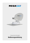
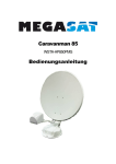
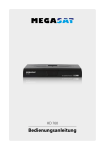
Campingman Portable
Twin Auto Skew
WSTA-PT250PMS
User manual
10
I
ntroduction
Portable antenna system is the innovative and a technologically advanced satellite In-Motion system.
Portable antenna has a unique combination of state-of-the art components with the most sophisticated
satellite acquisition and tracking programs to provide the following features :
■ Fast satellite acquisition
■ Compatible with any Satellite Receiver
■ Compatible with all Direct Broadcast Satellites
■ Built-in Digital Broadcast Receiver
■ Capable of High Definition receiving
Antenna System Overview
A complete satellite TV system, illustrated in Figure 1-1, includes Portable antenna
connected to a IDU, a satellite TV receiver, and a television set.
Portable
Antenna Unit
Satellite Receiver
TV
Antenna
Vehicle Power
12VDC~24VDC
or power supply
230VAC/12VDC 5A
TV
Receiver
IDU(In Door Unit)
11
System Components
Antenna Unit
The antenna unit houses the antenna positioning
mechanism, LNB (low noise block), and control
elements within a radome. Weathertight
connectors join the power, signal, and control
cabling from the below decks units.
IDU(InDoor Unit)
The IDU is the system’s user interface, providing
access to the system and its functions through an
LCD and three buttons. The IDU also serves as
the vehicle’s junction box, allowing the system
to use vehicle power, and supply and receive
data to/from the antenna unit.
12
I
nstallation
This section offers a general explanation of how properly to install Portable antenna.
Installation of Portable antenna must be accomplished by or under the supervision of an
authorized dealer for the Limited Warranty to be valid and in force. The steps in the
installation and setup process are as follows:
Unpacking the unit
1. Open box and remove packing material.
The following items are included in the packaging of Portable antenna.
Description
Item
Quantity
1
Portable Antenna Unit
1 each
2
IDU(In Door Unit)
1 each
3
Power Cable
1 each
4
Coaxial Cable (1m)
1 eack
5
Coaxial Cable (10m)
1 each
6
Coaxial Cable (10m)
1 each
7
User Manual
1 set
Preparing for the installation
Install Tools and Materials
Portable antenna system is designed for simple installation and setup. However, the following
list of equipment or items should be available during installation of Portable antenna.
1. Verification of the Vehicle’s Power Supply.
■ Confirm that the vehicle’s power supply is 12VDC~24VDC.
2. Verification of the Satellite Receiver and IDU’s attachment and the electricity supply
■ Attach Satellite Receiver and IDU in the interior of the vehicle or the trunk.
■ Connect the power of Satellite Receiver and IDU.
■ Once the power of Satellite Receiver and IDU is verified, it confirms that both
Satellite Receiver and IDU are working normally.
13
3. Procedure of the satellite’s attachment and installation.
■ Attach the satellite on the flat surface area of the vehicle’s roof.
■ Connect each end of the Coaxial antenna cable to the satellite’s terminal and the IDU.
■ Connect the IDU and the Satellite Receiver box together through the coaxial cable.
■ Make sure that the satellite is working normally, once the power is supplied.
Warning : Things to consider when installing the antenna.
■ Turn off the power when attaching or detaching the
antenna.
■ Make sure that the attached satellite is fixed on the flat
surface.
■ When attaching, ensure that all the products are adhered
properly.
■ Ensure that all the cables are connected properly.
Selecting the location
Determine the optimum mounting location for the antenna radom assembly. It should be
installed where :
1. The antenna has a clear line-of-sight view to as much of the sky as is practical. Choose
a location where masts or other structures do not block the satellite signal from the dish
as the vehicle turns.
2. The antenna is at least 5 feet away from other transmitting antennas (HF, VHF and
radar) that may generate signals that may interfere with Portable antenna. The further
away Portable antenna is from these other antennas, the less impact their operation will
have on it.
3. Direct radiation into the antenna from vehicles radar, especially high power
surveillance radar arrays, is minimized. The radom should be as far away from the
vehicles Radar as possible and should NOT be mounted on the same plane as the
vehicles Radar.
4. The antenna radome assembly should be rigidly mounted to the vehicle. If necessary,
reinforce the mounting area to assure that it does not flex due to the vehicle motion or
vibration.
If these conditions cannot be entirely satisfied, the site selection will inevitably be a “best”
compromise between the various considerations.
14
The antenna must have a clear view of the sky and the horizon at all the directions to
avoid blockage of the satellite signal.
bad or no signal
good signal
Selecting the location bad case
Equipment and cable installation
This offers a general explanation of how to install the IDU and satellite receiver properly to
the inside of vehicle connecting with coaxial cable.
1. The Coaxial cable is routed from the antenna to the IDU inside the vehicle.
2. After Once deciding where to place the IDU and satellite receiver, make sure that both
units are placed in a dry and protected area.
3. The IDU and satellite receiver should be placed away from any heat source and in an
area with proper ventilation.
4. Ensure that there are at least 3cm of space around both units for ventilation and
connection of cables. Do not stack the units on top of each other.
5. The following describes the basic wiring configurations for Portable antenna system.
■ Connect the Coaxial cable to Potable antenna port on the back of the IDU
■ Connect one end of the supplied coaxial cable to the receiver port on the back of
the IDU
■ Connect the other end of the coaxial cable to the satellite receiver
15
O
peration
Portable antenna system is easy to use. Under normal conditions, operation of Portable
antenna requires no intervention from the user. Antenna unit initialization and satellite
acquisition is completely automatic.
Receiving Satellite TV Signals
Television satellites are located in fixed positions above the Earth’s equator and beam TV
signals down to certain regions of the planet. To receive TV signals from a satellite, you must
be located within that satellite’s unique coverage area. To check it, see “Appendix A –
Satellite Coverage Map” In addition, since TV satellites are located above the equator,
Portable antenna must have a clear view of the sky to receive satellite TV signals. Anything
that stands between the antenna and the satellite can block the signal, resulting in lost
reception. Common causes of blockage include lighthouses, boat masts, trees, buildings, and
bridges. Heavy rain, ice, or snow might also temporarily interrupt satellite signals.
Turning the System On/Off
Since power to Portable antenna system is controlled by the IDU, you can turn the antenna
on or off by applying/removing operating power to the IDU.
Turning on the System
Follow the steps below to turn on your Portable antenna System.
1. Make sure the antenna has a clear view of the sky.
2. Turn on your satellite TV receiver and TV.
3. Apply operating power to the IDU.
4. Wait one minute for system startup. The IDU will display the Tracking
Satellite screen after system testing is complete.
Turning off the System
Follow the steps below to turn off your Portable antenna System.
1. Remove operating power from the IDU.
2. Turn off your satellite TV receiver and TV.
Changing Channels
If you have followed the installation instructions, your system should be set to the satellite of
your choice and the system should have downloaded the appropriate channel guides. When
Portable antenna system and satellite receiver is properly configured, it is easy to change the
channel using the remote control that normally comes with the receiver unit.
16
Watching TV
Portable antenna is designed to operate as efficiently and as reliably as possible when the
vehicle is moved and anchored. It is also the quickest satellite acquisition system available
among Portable antennas. If you have anchored the vehicle and the antenna has completed to
searching selected satellite, turn off IDU Power to avoid unnecessary use of power. Because
the LNB receives its power from the Satellite Receiver through the IDU, the antenna will
continue to receive the satellite TV signals.
Switching between Satellites
You can switch between satellites using the IDU by pressing Satellite select buttons. Follow
the steps below to switch to another satellite.
1. Ensure that the LEDs turn on. If antenna is disconnected, all led will blink.
LNB
POWER
LOCK
2. Press the Satellite select buttons to switch to another satellite.
3. The antenna shifts to track selected satellite. Wait for the Tracking Satellite
screen.
Operating the IDU
Appearance
Power S/W
LNB
ASTRA2
ASTRA
ASTRA4
HISPSAT/TURKSAT
ON
OFF
ASTRA3
POWER
LOCK
HOTBIRD
THOR
SATELLITE
SELECT
POWER
Satellite select button
17
Functions of LCD Display
Power S/W
You can change
the satellite by
pushing this
It is tracking a
satellite.
LNB
ASTRA 2
ON
OFF
POWER
ASTRA
ASTRA 3
LOCK
ASTRA4
HOTBIRD
HISPASAT/TURKSAT
THOR
SATELLITE
SELECT
POWER
It is Power.
It is in lock
mode.
Satellite select button
General Operation Order
Turn the power switch on.
ON
OFF
POWER
.
Push the Satellite select buttons to choose
satellite.
SATELLITE
SELECT
LNB
Power
Red LED turns on for searching the satellite.
LOCK
18
LNB
It is tracking the target satellite.
POWER
LOCK
LNB
Antenna lock choose satellite.
POWER
LOCK
In case of search failure
Turn the power switch on.
ON
OFF
POWER
Push the Satellite select buttons to choose
satellite.
SATELLITE
SELECT
LNB
Red LED turns on for searching the satellite.
POWER
LOCK
LNB
POWER
LOCK
If the antenna cannot find selected satellite,
it goes to sleep mode during about 2 minutes
with turning on 2-LED. And then the antenna
will search the satellite again.
19
T
r oubleshooting
There are a number of common issues that can affect the signal quality or the operation of
Portable antenna system. The following sections address these issues and potential solutions.
Simple check
Can the antenna see the satellite?
The antenna requires an unobstructed view of the sky to receive satellite TV
signals. Common causes of blockage include trees, buildings, bridges, and
mountains.
Is there excessive dirt or moisture on the antenna dome?
Dirt buildup or moisture on the dome can reduce satellite reception. Clean the
exterior of the dome periodically.
Is it raining heavily?
Heavy rain or snow can weaken satellite TV signals. Reception should improve
once the inclement weather subsides.
Is everything turned on and connected properly?
Make sure your TV and receiver are both turned on and set up for the satellite
input. Finally, check any connecting cables to ensure none have come loose.
Is the antenna’s LNB set to the correct skew angle?
To optimize reception, the antenna’s LNB needs to be set to the correct skew angle
for the satellite you want to track.
20
Causes and Remedies
Receiver Fault
Your satellite TV receiver might be set up incorrectly or defective. First check the
receiver’s configuration to ensure it is set up for the desired programming. In the
case of a faulty receiver, refer to your selected receiver’s user manual for service
and warranty information.
Satellite Coverage Issue
Television satellites are located in fixed positions above the Earth’s equator and
beam TV signals down to certain regions of the planet (not worldwide). To receive
TV signals from a satellite, you must be located within that satellite’s unique
coverage area. See “Appendix-A Satellite Coverage Map”
Satellite Signal Blocked
The Free Way 1S Antenna needs a clear line of sight (LOS), view to the satellite
for uninterrupted reception. Objects such as tall lighthouse, bridges and big ship
that block this view will cause a loss of signal. The signal will be quickly restored
once the antenna has a clear line of sight again. Heavy rain, cloud, snow or ice
may also interfere with the signal reception quality. If the satellite signal is lost due
to blockage or severe weather condition, services from the receiver will be lost
(picture will freeze frame and may disappear). When the satellite signal strength is
again high enough, then the receiver will resume providing desired programming
services.
Satellite Frequency Data Changed
If some channels work, while one or more other channels do not, or if the antenna
cannot find the selected satellite, the satellite’s frequency data might have
changed. You can visit any Continental-authorized dealer or distributor for
assistance or visit http://wwwMegasat.tv
Improper Wiring
If the system has been improperly wired, the antenna will not operate correctly.
Refer to the User Manual for complete system wiring information or visit website
(http://www.Megasat.tv)
Loose Cable Connectors
We recommends periodically checking the antenna unit’s cable connections. A
loose cable connector can reduce signal quality or prevent automatic satellite
switching using the receiver’s remote control. Fasten the cable connector.
21
Anlage A
AppendixA
Europa Position - Raster
Satellite Coverage Map
Bitte entnehmen Sie der Tabelle Ihre Postion (1-25)
Please refer to below table(1-25)
Die Skew Anpassung (LNB Winkel), finden Sie in der Liste (Skew Anpassung) .
Skew Adjustment(LNB Angle), find the table (Skew Adjustment)
22
Skew Anpassung
Skew Adjustment
Um die korrekte Skew Einstellung zu Überprüfen, entfernen Sie die Kuppel der
Antenne und vergleichen Sie die LNB Einstellung mit den Tabellenwerten.
If you want to check right skew set up, open the upper radome, compare the LNB angle with
below position.
Raster
Position
Grid
Position
TURKSAT
43°°E
ASTRA2
28.2°°E
ASTRA3
23.5°°E
ASTRA1
19.2°°E
HOTBIRD
13.0°°E
Astra4
4.8°°E
THOR
0.8°°W
AB3
5.0°°W
HISPASAT
30°°W
1
17°
13°
11°
10°
7°
3°
1°
-1°
-11°
2
14°
10°
8°
6°
4°
0°
-3°
-4°
-14°
3
11°
6°
4°
2°
-1°
-4°
-7°
-9°
-18°
4
6°
1°
-1°
-3°
-5°
-9°
-11°
-12°
-20°
5
2°
-2°
-4°
-6°
-9°
-12°
-14°
-15°
-22°
6
22°
17°
14°
12°
9°
4°
1°
-1°
-15°
7
19°
13°
10°
8°
5°
0°
-3°
-6°
-18°
8
15°
8°
5°
2°
-1°
-6°
-9°
-11°
-22°
9
8°
2°
-1°
-3°
-7°
-11°
-14°
-16°
-25°
10
1°
-3°
-6°
-8°
-11°
-15°
-18°
-20°
-27°
11
29°
21°
18°
16°
12°
6°
2°
-2°
-19°
12
25°
17°
13°
10°
6°
0°
-4°
-8°
-23°
13
20°
10°
6°
3°
-2°
-7°
-11°
-14°
-28°
14
10°
2°
-1°
-4°
-9°
-15°
-18°
-21°
-32°
15
1°
-4°
-7°
-10°
-14°
-20°
-23°
-25°
-34°
16
35°
27°
23°
20°
15°
8°
2°
-2°
-23°
17
30°
21°
17°
14°
8°
0°
-6°
-10°
-29°
18
24°
12°
8°
4°
-2°
-10°
-15°
-18°
-34°
19
13°
3°
-2°
-6°
-11°
-18°
-23°
-26°
-38°
20
1°
-5°
-9°
-13°
-18°
-25°
-28°
-31°
-41°
21
41°
33°
29°
25°
19°
9°
3°
-2°
-29°
22
36°
26°
21°
17°
10°
0°
-7°
-12°
-35°
23
29°
16°
10°
5°
-2°
-12°
-18°
-23°
-41°
24
16°
4°
-2°
-7°
-14°
-23°
-28°
-32°
-45°
25
2°
-6°
-11°
-16°
-23°
-30°
-34°
-37°
-48°
23
Ausleuchtzonen
Footprint
Astra 2N
Astra 2S
49dBW
49dBW
Astra 1
Hotbird
49dBW
49dBW
Fi
24
ASTRA4
Thor 2/3
49dBW
49dBW
ASTRA 3
TURKSAT
25
Atlantic Bird 3
Hispasat
49dBW
49dBW
Figure B-7 Atlantic bird 3
26
Technische Daten
Specification
Antennen Type
Parabola
Frequenz Band
Ku Band
Kuppel Abmessung
Diameter
Antennen Gewicht
Antenna weight
Antenna Gewinn
Antenna Gain
430x440mm
5kg
31dBi
Minimum EIRP
50dBW
Polarisation
V/H oder RHCP/LHCP
Type of Stabilisation
2-Axis Stepp Motor
Elevation Range
0° to 90°
Azimuth Range
Unlimited
Tracking Rate
50°/sec
Temperatur Bereich
Temperature Range
-20° to 70°
Power
12~24VDC
Megasat
Industriestrasse 4a
D- 97618 Niederlauer
Tel. +49 (0) 9771 63567-100
Fax. +49 (0) 9771 63567-144
Homepage www.megasat.tv
E-Mail: [email protected]
27