1
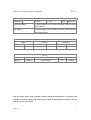
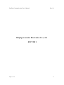
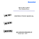
CS series Mass Flow Controller Profibus
Communication User’s Manual
Rev 1.0
02/28/2011
Profibus Communication User’s Manual
Rev 1.0
Beijing Sevenstar electronics Co., Ltd.
No.1 Jiuxianqiao East Rd. Chaoyang District
Beijing
China
Tel: +86 10 84564709
Fax: +86 10 64344958
Page 2 of 17
2
Profibus Communication User’s Manual
Rev 1.0
Identification
Reference
Revision
1.0 Test
Date
02/28/2011
Document Name
CS series Mass Flow Controller Profibus Communication
User’s Manual
File Name
CS series Mass Flow Controller Profibus Communication
User’s Manual.doc
Control
Author
Verified
Approved
Visa
Date
Visa
Date
Visa
Date
Zhao Di
02/28/2011 Mou Changhua 02/28/2011 Wang Maolin 02/28/2011
History
Author
Zhao Di
Date
Description
Revision
Status
02/28/2011
Initial Version
1.0
Issued
2011 Sevenstar, China. This document contains information proprietary to Sevenstar and
shall not be used for engineering, design, procurement or manufacture in whole or in part
without consent of Sevenstar.
Page 3 of 17
3
Profibus Communication User’s Manual
Rev 1.0
TABLE OF CONTENTS
1. Description…………………………………………………………………………. 5
2. Scope…………………………………………………………………………..……5
3. Introduction…………………………………………………………………………5
3.1 Definition…………………………………………………………………………... 5
3.2 Electrical Interfacing………………………………………………………………. 6
3.3 Address Selection………………………………………………………………….. 8
3.4 Baud Rates…………………………………………………………………………. 8
4. Slave configuration……………………………………………………………........9
4.1 Parameterization of the slave (MFC)……………………………………………….9
4.2 Configuration of the slave…………………………………………………………12
4.3 Diagnosis of the slave…………………………………………………………….. 14
Page 4 of 17
4
Profibus Communication User’s Manual
Rev 1.0
1. Description
This manual is designed for CS series digital Mass Flow Controller’s Profibus
application and programmers who want to develop a software to communicate with 1 or
several CS series Profibus Mass Flow Controllers.
For more details, please contact your Sevenstar sales representative.
2. Scope
This manual applies to Sevenstar CS series Profibus Mass Flow Controller (MFC).
3. Introduction
CS series Profibus MFC is a latest generation MFC for use in semiconductor
applications and demanding industrial uses where its high accuracy and flexibility in
interfacing are required. CS series Profibus MFC supports Profibus-DP communication.
3.1 Definition
GSD file
The GSD file contains the characteristic device data of the product, i.e.
the device profile.
Input/Output
Profibus-DP conventions define all input/output directions as seen from
the master system.
Data transferred by the master to the slave (e.g.commands, setpoints) is
referred to as ‘output data’.
Slave (sensor) data to be transferred to the master is referred to as ‘input
data’.
Profibus-FMS
Process field bus-Fieldbus Message Specification. Profibus protocol for
high-level, object oriented data communication.
Can be operated together with Profibus-DP.
Profibus-DP
Process field bus-Decentralized Periphery. Profibus protocol for highspeed, cyclic data communication.
Profibus-PA
Process
field
bus-Process
Automation.
Profibus
protocol
for
intrinsically safe data communication.
PI
Profibus International.
PNO
Profibus Nutzer Organization.
Page 5 of 17
5
Profibus Communication User’s Manual
VPC3
Rev 1.0
Profibus-DP ASIC. Component manufactured by Profichip to provide
Profibus-DP slave functionality to a host processor.
ASIC
Application Specific Integrated Circuit.
MFC
Mass Flow Controller.
Bit
Smallest binary information representation: 0 or 1.
Byte or Octet
Binary number representation, consists of 8 bits. Represents 1 value or
8 situations (‘bitmapped’). Bits in a byte are numbered from right to left,
i.e. least significant bit is bit 0, most significant bit is bit 7.
Examples:
Value: binary 00110011 = 51 decimal
Bitmapped: binary 00010111 = bits 0,1,2 and 4 are true, others are false.
Word
Combination of 2 bytes or 16 bits. Represents 1 value or 16 situations
(‘bitmapped’).
Examples:
Value: binary 00010001 00110011 = 4403 decimal
Bitmapped: binary 00010001 00010111 = bits 0,1,2,4,8 and 12 are true,
others are false.
3.2 Electrical Interfacing
3.2.1 General
With simple switching power supply, CS series MFC is available for ±8 to ±16VDC
(dual-ending) and +14 to +28VDC (single-ending). Customer can choose as need.
CS series Profibus MFC has 15-pin male Sub-D and 9-pin female Sub-D connectors.
15-pin male Sub-D connector provides 0~5V analog setpoint signal, flow output signal
and RS485 communication. 9-pin female Sub-D connector is Profibus-DP connector.
CS series Profibus MFC can communicate with PC via RS485 or Profibus.
3.2.2 Connections
The 15-pin male Sub-D connector and 9-pin female Sub-D connector are shown in
Figure2-1 and Figure 2-2.
Page 6 of 17
6
Profibus Communication User’s Manual
Rev 1.0
Figure2-1 15-pin male Sub-D connector
Figure2-2 9-pin female Sub-D connector
Page 7 of 17
7
Profibus Communication User’s Manual
Rev 1.0
3.3 Address Selection
Every MFC on Profibus network requires unique communication address in order to
correctly communicate with the master device. CS series Profibus MFC has address in
the range 1 through 125.
MFC’s address selection is implemented by two rotary switches located on the top
side of the MFC. Refer to Figure 3-1. Each of the switches allows a setting of an integer
number, the units between 0 and 9 and the decimals 0 and 12. The decimal address digit
indicates the multiples of ten, whereas the unit address digit indicates the multiples of one.
Therefore the allowable station address number ranges from 0 to 125.
The decimal switch has a labelling from 0 through F, which is hexadecimal. The
letters A through F represents 10 through 15. The letter D, E and F are not allowed since
they represent addresses in the range 130, 140 and 150, which is outside the Profibus
range of 125.
Figure3-1 Address Rotary Switch Layout
3.4 Baud Rates
Since CS series MFC’s Profibus-DP interface has been implemented using the
Profichip VPC3 slave ASIC, the baud rates supported are determined by the capabilities
of this component. The baud rates supported are 9600bps, 19.2kbps, 45.45kbps,
93.75kbps, 187.5kbps, 500kbps, 1.5Mbps, 3Mbps, 6Mbps and 12Mbps.
Page 8 of 17
8
Profibus Communication User’s Manual
Rev 1.0
The VPC3 supports automatic baud rate detection. Therefore no hardware means are
necessary to select the required baud rate at the slave. Communication initiated by the
master at a any of the supported baud rate values will cause the CS series Profibus MFC
to lock on to this baud rate after an automatic search for it.
4 Slave configuration
4.1 Parameterization of the slave (MFC)
Byte
Definition
1-7
Bus parameters (System parameters)
8
Code for VPC3 ASIC
9
Reserved
10
Failsafe state
11
Alarm option
12
Warning option
13
Reserved
14
Softstart selection
15
Softstar data (%/sec)
16
Flow unit
17
Temperature unit
18
Totalize unit
19
Setpoint source
20
Valve command mode
The parameters are described more in detail on the next pages.
Page 9 of 17
9
Profibus Communication User’s Manual
Byte
Bit
Rev 1.0
Type
Range
Default Options
Description
8
Byte
/
0
Reserved
9
byte
/
0
Reserved
10
byte
0-3
1
0 = no effect
Select emergency state if
1 = Valve close
communication is lost
2 = setpoint=0.0
3 = Valve open
11
0
Bit
0-1
0
0 = disable
Temperature alarm
1 = enable
1
Bit
0-1
0
0 = disable
Sensor drift alarm
1 = enable
2
Bit
0-1
0
0 = disable
Valve alarm
1 = enable
3
Bit
0-1
0
0 = disable
EEPROM alarm
1 = enable
12
4
Bit
/
0
Reserved
5
Bit
/
0
Reserved
6
Bit
/
0
Reserved
7
Bit
/
0
Reserved
0
Bit
0-1
0
0 = disable
Temperature warning
1 = enable
1
Bit
0-1
0
0 = disable
Sensor drift warning
1 = enable
2
Bit
/
0
Reserved
3
Bit
/
0
Reserved
4
Bit
/
0
Reserved
5
Bit
/
0
Reserved
6
Bit
/
0
Reserved
7
Bit
/
0
Reserved
byte
/
0
Reserved
13
Page 10 of 17
10
Profibus Communication User’s Manual
14
Byte
0-1
0
Rev 1.0
0 = off
Softstart selection
1 = enable
15
Byte
0-100
0
%/sec
Softstar data
16
Byte
0-12
0
0 = %FS
Flow unit
1 = ml/sec
2 = ml/min
3 = ml/hour
4 = Liter/sec
5 = Liter/min
6 = Liter/hour
7 = M3/sec
8 = M3/min
9 = M3/hour
10 = Ft3/sec
11 = Ft3/min
12 = Ft3/hour
17
Byte
0-2
1
0 = Kelvin
Temperature unit
1 = Celsius
2 = Fahrenheit
18
Byte
0-3
0
0 = ml
Totalize unit
1 = liter
2 = m3
3 = ft3
19
Byte
1-3
3
1 = RS485
Setpoint source
2 = 0-5Vdc
3 = Profibus
20
Byte
0-2
2
0 = Mode0
Valve command mode
1 = Mode1
2 = Mode2
21
Page 11 of 17
Byte
/
0
Reserved
11
Profibus Communication User’s Manual
Rev 1.0
4.2 Configuration of the slave
According to respective I/O data requirement customer can select one of the
following three Modules.
Module
Code
Description
Module1
0x C1
Special identifier with one length byte each for Output and Input
follows, with one byte of manufacturer special data.
Module2
0x 83
Output data, 4 bytes (1 float)
0x 83
Input data, 4 bytes (1 float)
0x 01
Manufacturer special data, module 1.
0x C1
Special identifier with one length byte each for Output and Input
follows, with one byte of manufacturer special data.
Module3
0x 84
Output data, 5 bytes (1 float + 1 byte)
0x 88
Input data, 9 bytes (2 floats + 1 byte)
0x 02
Manufacturer special data, module 2.
0x C1
Special identifier with one length byte each for Output and Input
follows, with one byte of manufacturer special data.
0x 84
Output data, 5 bytes (1 float + 1 byte)
0x 94
Input data, 21 bytes (4 floats + 1 unsigned integer + 1 byte)
0x 03
Manufacturer special data, module 3.
I/O memory map Mass Flow Controller SCS.gsd
Module1: “out[Setp], in[Flow]”
Output
description
byte #
byte size
type
Setp
setpoint
0…..3
4
floating point
Input
description
byte #
byte size
type
Flow
flow
0…..3
4
floating point
Page 12 of 17
12
Profibus Communication User’s Manual
Rev 1.0
I/O memory map Mass Flow Controller SCS.gsd
Module2: “out[Setp,CMD], in[Flow,Tot,CMD]”
Output
description
byte #
byte size
type
Setp
setpoint
0…..3
4
floating point
CMD
command
4
1
unsigned byte
Input
description
byte #
byte size
type
Flow
flow
0…..3
4
floating point
Tot
totalizer
4…..7
4
floating point
CMD
command
8
1
unsigned byte
I/O memory map Mass Flow Controller SCS.gsd
Module3: “out[Setp,CMD], in[Setp,Flow,Temp,Tot,Valv,CMD,]”
Output
description
byte #
byte size
type
Setp
setpoint
0…..3
4
floating point
CMD
command
4
1
unsigned byte
Input
description
byte #
byte size
type
Setp
actual setpoint of the MFC
0…..3
4
floating point
Flow
flow
4…..7
4
floating point
Temp
temperature
8….11
4
floating point
Tot
totalizer
12…15
4
floating point
Valv
valve current value
16…19
4
unsigned integer
CMD
command
20
1
unsigned byte
The function of CMD is totalizer and valve override. The details are shown in the
following table.
Page 13 of 17
13
Profibus Communication User’s Manual
Rev 1.0
Function: CMD
bit#
range
default
options
0…3
0…3
0
Valve Override command
0= Normal control
1= Valve shut off
2= Valve Max Value
3= Valve Hold
4…7
0…2
0
Totalizer command
0= Stop totalizer
1= Begin totalize
2= Reset totalizer
4.3 Diagnosis of the slave
CS series Profibus MFC can provide the function of diagnosis. When the MFC’s
sensor, valve, EEPROM or temperature has any error, MFC will send diagnostics
message to Profibus master. The following table summarizes the diagnostic data bytes to
be sent at the event of an error.
Diagnostics message
Byte0
Byte1
Fatal system Alarm
Fatal
Warning
Byte2
Byte3
system Non Fatal system Non
Alarm
Fatal
system
Warning
For detailed information please refer to the following tables.
Page 14 of 17
14
Profibus Communication User’s Manual
Rev 1.0
Diagnostics byte 0: Fatal system Alarm
Bit
Diagnosis
Value
Bit 7
Sensor negative drift Alarm
0=normal ; 1=alarm
Bit 6
Reserved
0
Bit 5
Valve open Alarm
0=normal ; 1=alarm
Bit 4
Valve short Alarm
0=normal ; 1=alarm
Bit 3
EEPROM Alarm
0=normal ; 1=alarm
Bit 2
Sensor Positive drift Alarm
0=normal ; 1=alarm
Bit 1
Reserved
0
Bit 0
Reserved
0
Diagnostics byte 1: Fatal System Warning
Bit
Diagnosis
Value
Bit 7
Sensor negative drift Warning
0=normal ; 1 warning
Bit 6
Sensor Positive drift Warning
0=normal ; 1 warning
Bit 5
Reserved
0
Bit 4
Reserved
0
Bit 3
Reserved
0
Bit 2
Reserved
0
Bit 1
Reserved
0
Bit 0
Reserved
0
Page 15 of 17
15
Profibus Communication User’s Manual
Rev 1.0
Diagnostics byte 2: Non Fatal system Alarm
Bit
Diagnosis
Value
Bit 7
Temperature Low Alarm
0=normal ; 1=alarm
Bit 6
Temperature High Alarm
0=normal ; 1=alarm
Bit 5
Reserved
0
Bit 4
Reserved
0
Bit 3
Reserved
0
Bit 2
Reserved
0
Bit 1
Reserved
0
Bit 0
Reserved
0
Diagnostics byte 3: Non Fatal system Warning
Bit
Diagnosis
Value
7
Temperature Low Warning
0=normal ; 1=alarm
6
Temperature High Warning
0=normal ; 1=alarm
5
Reserved
0
4
Reserved
0
3
Reserved
0
2
Reserved
0
1
Reserved
0
0
Reserved
0
Page 16 of 17
16
Profibus Communication User’s Manual
Rev 1.0
Beijing Sevenstar Electronics Co., Ltd.
02/17/2011
Page 17 of 17
17