1
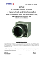
LYNX Hardware User’s Manual
LYNX
Hardware User’s Manual
( CameraLink and GigE models )
HIGH-RESOLUTION, FAST, FIELD UPGRADEABLE,
PROGRAMMABLE, 8/10/12 BIT
DIGITAL CAMERAS
CONFIDENTIAL NOTICE:
These products are not intended for use in life support appliances, devices, or systems where malfunction of these
products can reasonably be expected to result in personal injury. Imperx customers using or selling these products for
use in such applications do so at their own risk and agree to fully indemnify Imperx for any damages resulting from
such improper use or sale.
Copyright © 2005, Imperx Inc. All rights reserved. All information provided in this manual is believed to be accurate
and reliable. Imperx assumes no responsibility for its use. Imperx reserves the right to make changes to this
information without notice. Redistribution of this manual in whole or in part, by any means, is prohibited without
obtaining prior permission from Imperx.
Imperx, Inc.
6421 Congress Ave.
Boca Raton, FL 33487
+1 (561) 989-0006
Rev. 11
1/21/2008
1 of 216
LYNX Hardware User’s Manual
Revision History
Rev. 1
Rev. 2
Rev. 3
12/15/05 P. Dinev
1/04/06 G. Angelone
1/23/06 J. Egri
Rev. 4
2/28/06
J. Egri
Rev. 5
3/16/06
J. Egri
Rev. 6
5/04/06
J. Egri
Rev. 7
07/21/06 J. Egri
Rev. 8
03/09/07 J. Egri
Rev. 9
03/20/07 J. Egri
Rev. 10
Rev. 11
01/10/08 B. Rynk
01/21/08 B. Rynk
Initial release.
Modify driver installation to select Pro1000.inf
Updated Appendix B - LynxTerminal to reflect the
addition of GigE support.
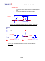
Added illustrations of the External Trigger input and
Strobe output circuits for GigE camera.
Added note about Escape Markers to section 3.3
Added new features and commands for: Defective
Pixel Correction, Flat Field Correction and
Programmable Frame Time.
Updated Chapter 4 - LynxConfigurator
Updated Appendix B - LynxTerminal
Updated section 2.2.2 - ‘Calculating the Frame Rate
using Vertical Window’ for the IPX-11M5 camera
Added support for 2M30, 2M30H and 4M15 to Flat
Field Correction.
Changed description of Section 2.10 – Dynamic
Signal-to-Noise Correction.
Removed GigE application GUI description in section
5.3. A detailed description of the GUI can be found
in the LYNX Software User’s Manual.
Updated sections 3.8.6 and 3.8.7 - added third
parameter to ‘sag’ and ‘sao’ commands.
Fixed Strobe Position text in section 3.8.5.1
Added support for IPX-16M3 camera
Corrected timing diagrams figures 2.15 and 2.25
Added programmable STROBE to figures 2.42 – 2.44
Corrected text for SVM command in 3.8.13.1
Added figures 1.9 and 1.16 for the Peltier cameras
IPX-4M15T / 11M5T / 16M3T
Added TEC description in section 2.18
Added Appendix F – Lynx TEC Operating Manual
Modified commands in Appendix F
2 of 216
LYNX Hardware User’s Manual
Table of Contents
Chapter 1 – Introduction _______________________________________________________ 14
1.1
LYNX FAMILY ______________________________________________________ 15
1.2
GENERAL DESCRIPTION ____________________________________________ 17
1.3
LYNX TECHNICAL SPECIFICATIONS ________________________________ 19
1.4
CAMERA CONNECTIVITY ___________________________________________
1.4.1
Camera Link Output _______________________________________________
1.4.2
GigE Output ______________________________________________________
1.4.3
Power Supply _____________________________________________________
25
25
29
31
1.5
MECHANICAL, OPTICAL and ENVIRONMENTAL _____________________
1.5.1
Mechanical_______________________________________________________
1.5.2
Optical __________________________________________________________
1.5.3
Environmental ____________________________________________________
32
32
54
55
Chapter 2 – Camera Features ___________________________________________________ 56
2.1
RESOLUTION AND FRAME RATE ____________________________________
2.1.1
Single Output _____________________________________________________
2.1.2
Dual Output ______________________________________________________
2.1.3
Center Columns Output (IPX-VGA210-L/G only) ________________________
2.1.4
Timing Diagrams __________________________________________________
IPX-VGA120-L, IPX-VGA210-L/G ________________________________________
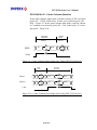
IPX-VGA210-L/G – Center Columns Operation_____________________________
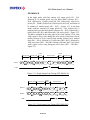
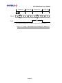
IPX-1M48-L/G _________________________________________________________
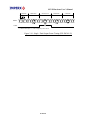
IPX-2M30-L/G _________________________________________________________
IPX-2M30H-L/G ________________________________________________________
IPX-4M15-L/G _________________________________________________________
IPX-11M5-L/G _________________________________________________________
IPX-16M3-L/G _________________________________________________________
57
57
58
59
61
61
63
64
66
68
70
72
74
2.2
AREA OF INTEREST ________________________________________________
2.2.1
Horizontal and Vertical Window ______________________________________
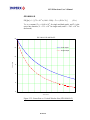
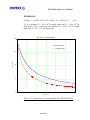
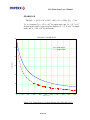
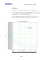
2.2.2
Calculating the Frame Rate using Vertical Window _______________________
IPX-VGA120-L _________________________________________________________
IPX-VGA210-L/G_______________________________________________________
IPX-1M48-L/G _________________________________________________________
IPX-2M30-L/G _________________________________________________________
IPX-4M15-L/G _________________________________________________________
IPX-11M5-L/G _________________________________________________________
IPX-16M3-L/G _________________________________________________________
76
76
77
78
79
80
81
82
83
84
2.3
BINNING ___________________________________________________________ 85
2.4
EXPOSURE CONTROL ______________________________________________ 87
3 of 216
LYNX Hardware User’s Manual
2.4.1
2.4.2
2.4.3
Electronic Shutter__________________________________________________ 87
Variable Frame Rate – Programmable Integration ________________________ 87
Long Integration___________________________________________________ 88
2.5
EXTERNAL TRIGGER _______________________________________________
2.5.1
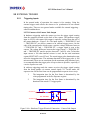
Triggering Inputs __________________________________________________
2.5.2
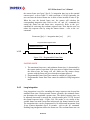
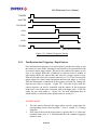
Standard Triggering - Programmable Exposure __________________________
2.5.3
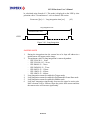
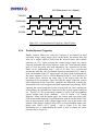
Fast Synchronized Triggering – Rapid Capture___________________________
2.5.4
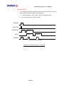
Double Exposure Triggering _________________________________________
90
90
92
93
94
2.6
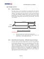
STROBE OUTPUT ___________________________________________________
2.6.1
Strobe Positioning _________________________________________________
2.6.2
Strobe Electrical Connectivity – LYNX with Camera Link Output ___________
2.6.3
Strobe Electrical Connectivity – LYNX with GigE Output _________________
96
96
96
98
2.7
GAIN and OFFSET ___________________________________________________ 99
2.8
DATA OUTPUT FORMAT ___________________________________________ 100
2.9
TRANSFER FUNCTION CORRECTION – USER LUT ___________________ 101
2.9.1
Standard Gamma Correction ________________________________________ 101
2.9.2
User Defined LUT - Examples ______________________________________ 102
2.10
DYNAMIC SIGNAL-TO-NOISE CORRECTION ________________________ 107
2.11
IMAGE REVERSAL_________________________________________________ 108
2.12
NEGATIVE IMAGE _________________________________________________ 109
2.13 CAMERA INTERFACE ______________________________________________
2.13.1 Status LED ______________________________________________________
2.13.2 Temperature Monitor ______________________________________________
2.13.3 Integration Time Monitor __________________________________________
2.13.4 Frame Rate Monitor_______________________________________________
110
110
110
111
111
2.14
TEST MODE _______________________________________________________ 112
2.15
AUTOMATIC IRIS CONTROL _______________________________________ 113
2.16
DEFECTIVE PIXEL CORRECTION __________________________________ 113
2.17
FLAT FIELD CORRECTION _________________________________________ 114
2.18
THERMO-ELECTRIC COOLING ( TEC )______________________________ 116
Chapter 3 – Camera Configuration ______________________________________________ 117
3.1
Overview ___________________________________________________________ 118
3.2
Configuration Memory _______________________________________________ 119
3.3
Command Format ___________________________________________________ 120
3.4
Command Help _____________________________________________________ 121
3.5
Startup procedure ___________________________________________________ 122
3.6
Saving and Restoring Settings _________________________________________ 123
4 of 216
LYNX Hardware User’s Manual
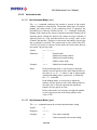
Set Boot From (‘sbf’) ______________________________________________
Get Boot From (‘gbf’) ______________________________________________
Load From Factory (‘lff’) ___________________________________________
Load From User (‘lfu’) _____________________________________________
Save To Factory (‘stf’) _____________________________________________
Save To User (‘stu’) _______________________________________________
123
123
123
124
124
124
3.7
Retrieving Manufacturing Data ________________________________________
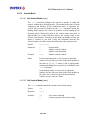
3.7.1
Get Manufacturing Data (‘gmd’)______________________________________
3.7.2
Get Assembly Number (‘gan’) _______________________________________
3.7.3
Get Model Number (‘gmn’)__________________________________________
3.7.4
Get Firmware Version (‘gfv’) ________________________________________
3.7.5
Get Software Version (‘gsv’) ________________________________________
125
125
125
125
125
126
3.8
Command Description________________________________________________
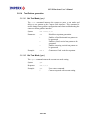
3.8.1
Horizontal Window _______________________________________________
3.8.1.1
Set Horizontal Window (‘shw’) _________________________________
3.8.1.2
Get Horizontal Window (‘ghw’) _________________________________
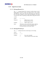
3.8.2
Vertical Window _________________________________________________
3.8.2.1
Set Vertical Window (‘svw’)____________________________________
3.8.2.2
Get Vertical Window (‘gvw’) ___________________________________
3.8.3
Shutter Time_____________________________________________________
3.8.3.1
Set Shutter Time (‘sst’) _______________________________________
3.8.3.2
Get Shutter Time (‘gst’) _______________________________________
3.8.4
Long Integration__________________________________________________
3.8.4.1
Set Long Integration (‘sli’) _____________________________________
3.8.4.2
Get Long Integration (‘gli’) ____________________________________
3.8.5
Strobe Position ___________________________________________________
3.8.5.1
Set Strobe Position (‘ssp’)_____________________________________
3.8.5.2
Get Strobe Position (‘gsp’) ____________________________________
3.8.6
Analog Gain _____________________________________________________
3.8.6.1
Set Analog Gain (‘sag’) _______________________________________
3.8.6.2
Get Analog Gain (‘gag’) _______________________________________
3.8.7
Analog Offset____________________________________________________
3.8.7.1
Set Analog Offset (‘sao’) ______________________________________
3.8.7.2
Get Analog Offset (‘gao’) ______________________________________
3.8.8
Dual Tap mode___________________________________________________
3.8.8.1
Set Dual Mode (‘sdm’) ________________________________________
3.8.8.2
Get Dual Mode (‘gdm’)________________________________________
3.8.9
Bit Depth _______________________________________________________
3.8.9.1
Set Bit Depth (‘sbd’) __________________________________________
3.8.9.2
Get Bit Depth (‘gbd’)__________________________________________
3.8.10 Lookup Table Operation ___________________________________________
3.8.10.1 Set Lookup Table (‘slt’) _______________________________________
3.8.10.2 Get Lookup Table (‘glt’) _______________________________________
3.8.10.3 Get Lookup Header (‘glh’) _____________________________________
3.8.11 Noise Correction processing ________________________________________
127
127
127
127
128
128
128
129
129
129
130
130
130
131
131
131
132
132
132
133
133
133
134
134
134
135
135
135
136
136
136
136
137
3.6.1
3.6.2
3.6.3
3.6.4
3.6.5
3.6.6
5 of 216
LYNX Hardware User’s Manual
3.8.11.1 Set Noise Correction (‘snc’) ___________________________________
3.8.11.2 Get Noise Correction (‘gnc’) ___________________________________
3.8.12 Horizontal mode__________________________________________________
3.8.12.1 Set Horizontal Mode (‘shm’) ___________________________________
3.8.12.2 Get Horizontal Mode (‘ghm’) ___________________________________
3.8.13 Vertical Mode ___________________________________________________
3.8.13.1 Set Vertical Mode (‘svm’)______________________________________
3.8.13.2 Get Vertical Mode (‘gvm’) _____________________________________
3.8.14 Test Pattern generation ____________________________________________
3.8.14.1 Set Test Mode (‘gtm’)_________________________________________
3.8.14.2 Get Test Mode (‘gtm’) ________________________________________
3.8.15 Image Reversal mode______________________________________________
3.8.15.1 Set Image Reversal (‘sir’) _____________________________________
3.8.15.2 Get Image Reversal (‘gir’) _____________________________________
3.8.16 Trigger operation _________________________________________________
3.8.16.1 Set Trigger (‘str’)_____________________________________________
3.8.16.2 Get Trigger (‘gtr’) ____________________________________________
3.8.16.3 Set Trigger Duration (‘std’) ____________________________________
3.8.16.4 Get Trigger Duration (‘gtd’) ____________________________________
3.8.16.5 Set CC Integration (‘sci’) ______________________________________
3.8.16.6 Get CC Integration (‘gci’)______________________________________
3.8.16.7 Set Pre-Exposure (‘spe’) ______________________________________
3.8.16.8 Get Pre-Exposure (‘gpe’)______________________________________
3.8.16.9 Set Double Exposure (‘sde’) ___________________________________
3.8.16.10 Get Double Exposure (‘gde’) __________________________________
3.8.17 Negative Image mode _____________________________________________
3.8.17.1 Set Negative Image (‘sni’)_____________________________________
3.8.17.2 Get Negative Image (‘gni’) ____________________________________
3.8.18 Temperature Monitoring ___________________________________________
3.8.18.1 Get Current Temperature (‘gct’) ________________________________
3.8.18.2 Set Temperature Alarm (‘sta’) _________________________________
3.8.18.3 Get Temperature Alarm (‘gta’) _________________________________
3.8.18.4 Set Temperature Threshold (‘stt’) ______________________________
3.8.18.5 Get Temperature Threshold (‘gtt’) ______________________________
3.8.19 Programmable Frame Rate _________________________________________
3.8.19.1 Set Frame Rate (‘sfr’) ________________________________________
3.8.19.2 Get Frame Rate (‘gfr’) ________________________________________
3.8.19.3 Set Frame Time (‘sft’) ________________________________________
3.8.19.4 Get Frame Time (‘gft’) ________________________________________
3.8.20 Current Speed and Exposure ________________________________________
3.8.20.1 Get Camera Speed (‘gcs’)_____________________________________
3.8.20.2 Get Camera Exposure (‘gce’) __________________________________
3.8.21 Defective Pixel Correction__________________________________________
3.8.21.1 Set Defect Correction (‘sdc’)___________________________________
3.8.21.2 Get Defect Correction (‘gdc’) __________________________________
3.8.21.3 Dump Pixel Map (‘dpm’) ______________________________________
6 of 216
137
137
138
138
138
139
139
139
140
140
140
141
141
141
142
142
142
143
143
143
143
144
144
145
145
146
146
146
147
147
147
147
148
148
149
149
149
150
150
151
151
152
153
153
153
153
LYNX Hardware User’s Manual
3.8.22 Flat Field Correction ______________________________________________
3.8.22.1 Set Flatfield Correction (‘sfc’) __________________________________
3.8.22.2 Get Flatfield Correction (‘gfc’)__________________________________
3.8.22.3 Get Flatfield Header (‘gfh’) ____________________________________
154
154
154
154
Chapter 4 – LYNX Configurator for CameraLink __________________________________ 155
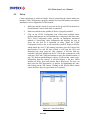
4.1
Overview ___________________________________________________________ 156
4.2
Setup ______________________________________________________________ 157
4.3
Graphical User Interface______________________________________________
4.3.1
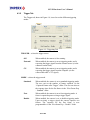
Area of Interest (AOI) Tab _________________________________________
4.3.2
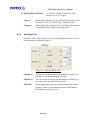
Trigger Tab _____________________________________________________
4.3.3
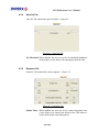
Video Amp Tab __________________________________________________
4.3.4
Auto Iris Tab ____________________________________________________
4.3.5
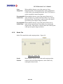
Exposure Tab ____________________________________________________
4.3.6
Strobe Tab ______________________________________________________
4.3.7
Common Controls ________________________________________________
159
159
161
162
163
163
164
165
Chapter 5 – LYNX Interface Application for GigE __________________________________ 169
5.1
Overview ___________________________________________________________ 170
5.2
Setup ______________________________________________________________ 171
5.3
Graphical User Interface______________________________________________ 172
Chapter 6 – Warranty and Support ______________________________________________ 173
6.1
ORDERING INFORMATION_________________________________________ 174
6.2
TECHNICAL SUPPORT _____________________________________________ 175
6.3
WARRANTY _______________________________________________________ 176
Appendix A – Camera Configuration Reference____________________________________ 177
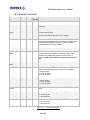
A.1 General Commands ____________________________________________________ 178
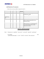
A.2 Retrieving Manufacturing Data __________________________________________ 179
A.3 Retrieving Camera Performance__________________________________________ 179
A.4 Restricted Commands___________________________________________________ 180
A.5 Configuring Workspace Settings__________________________________________ 181
A.6 Retrieving workspace settings ____________________________________________ 185
Appendix B – Lynx Terminal ___________________________________________________ 189
B.1 Overview _____________________________________________________________ 190
B.2 Setup _________________________________________________________________ 190
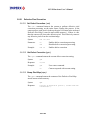
B.3 Download Utility _______________________________________________________ 196
B.4 Terminal Utility ________________________________________________________ 197
Appendix C – Creating Look Up Tables __________________________________________ 198
7 of 216
LYNX Hardware User’s Manual
C.1 Overview _____________________________________________________________ 199
C.2 Using an ASCII text editor_______________________________________________ 199
C.3 Using Microsoft Excel___________________________________________________ 200
Appendix D – LYNX CameraLink Software Installation _____________________________ 201
D.1 Software Suite _________________________________________________________ 202
D.2 Software Installation from CD____________________________________________ 203
D.3 Software Upgrade from Web Site _________________________________________ 203
Appendix E – LYNX GigE Software Installation ___________________________________ 205
E.1 Software Suite _________________________________________________________ 206
E.2 Software and Driver Installation from CD __________________________________ 206
E.3 Software Upgrade from Web Site _________________________________________ 208
E.4 Driver, Software and SDK Documentation _________________________________ 209
Appendix F – LYNX TEC Operating Manual ______________________________________ 210
F.1 Introduction ___________________________________________________________ 211
F.2 Control Tab ___________________________________________________________ 211
F.3 Constant Power Mode___________________________________________________ 212
F.4 Constant Temperature Mode _____________________________________________ 213
F.5 Operating Modes _______________________________________________________ 213
F.6 Commands ____________________________________________________________ 215
F.7 Configuration Settings __________________________________________________ 216
F.8 Maintenance___________________________________________________________ 216
8 of 216
LYNX Hardware User’s Manual
List of Figures
Figure 1.0 - CCD Pixel Structure................................................................................................... 19
Figure 1.1 - Spectral response – monochrome quantum efficiency ............................................. 20
Figure 1.2 - Spectral response – color quantum efficiency........................................................... 21
Figure 1.3 - Spectral response – UV quantum efficiency ............................................................. 21
Figure 1.4 - Camera Back Panel – Camera Link Output ............................................................. 25
Figure 1.5a - Camera Output Connector....................................................................................... 25
Figure 1.5b - Camera Power Connector – Camera Link Output (viewed from rear).................. 28
Figure 1.6a - Camera Back Panel – GigE Output ........................................................................ 29
Figure 1.6b - Camera Power Connector GigE Output (viewed from rear) .................................. 30
Figure 1.7a - C-mount camera link cameras – IPX-VGA-L / 1M48-L / 2M30-L / 2M30H -L ... 32
Figure 1.7b - F-mount camera link cameras – IPX-4M15-L / 11M5-L / IPX-16M3-L............... 32
Figure 1.8a - C-mount GigE cameras – IPX-VGA-G / 1M48-G / 2M30-G / 2M30H-G.............. 33
Figure 1.8b - F-mount GigE cameras – IPX-4M15-G / 11M5-G / 16M3-G ................................ 33
Figure 1.9 – Peltier cooled CL and GigE cameras – IPX-4M15T / 11M5T / 16M3T.................. 34
Figure 1.10a - IPX-VGA120-L and IPX-VGA210-L Dimensional Drawings.............................. 35
Figure 1.10b - IPX-VGA210-G (Silver Body) Dimensional Drawings......................................... 36
Figure 1.11a - IPX-1M48-L Dimensional Drawings .................................................................... 38
Figure 1.11b - IPX-1M48-G (Silver Body) Dimensional Drawings ............................................. 39
Figure 1.12a - IPX-2M30-L and IPX-2M30H-L Dimensional Drawings.................................... 41
Figure 1.12b - IPX-2M30-G and IPX-2M30H-G (Silver Body) Dimensional Drawings ............ 42
Figure 1.12c - IPX-2M30-G and IPX-2M30H-G (Black Body) Dimensional Drawings ............ 43
Figure 1.13a - IPX-4M15-L Dimensional Drawings .................................................................... 44
Figure 1.13b - IPX-4M15-G (Silver Body) Dimensional Drawings ............................................. 45
Figure 1.14a - IPX-11M5-L (Silver Body) Dimensional Drawings.............................................. 47
Figure 1.14b - IPX-11M5-L (Black Body) Dimensional Drawings.............................................. 48
Figure 1.14c - IPX-11M5-G (Silver Body) Dimensional Drawings.............................................. 49
Figure 1.14d - IPX-11M5-G (Black Body) Dimensional Drawings ............................................. 50
Figure 1.15a - IPX-16M3-L Dimensional Drawings .................................................................... 51
Figure 1.15b - IPX-16M3-G Dimensional Drawings .................................................................... 52
Figure 1.16 – IPX-4M15T/11M5T/16M3T Dimensional Drawings............................................. 53
Figure 1.17 - C-mount and F-mount adapter................................................................................ 54
9 of 216
LYNX Hardware User’s Manual
Figure 2.1 - Single Output Mode of Operation.............................................................................. 57
Figure 2.2 - Dual Output Mode of Operation................................................................................ 58
Figure 2.3 - Center columns output mode of operation ................................................................ 59
Figure 2.4 - Center Columns Output in Dual Mode of Operation ............................................... 60
Figure 2.5 - Center Columns Output in Dual Tap Mode .............................................................. 60
Figure 2.6 - Single Output Line Timing (IPX-VGA120/210-L and IPX-210-G) ......................... 61
Figure 2.7 - Dual Output Line Timing (IPX-VGA210-L/G)......................................................... 62
Figure 2.8 - Single / Dual (Center) Output Frame Timing (IPX-VGA210-L/G) ......................... 62
Figure 2.9 - Center Columns Single Output Line Timing (IPX-VGA210-L/G)........................... 63
Figure 2.10 - Center Columns Dual Output Line Timing (IPX-VGA210-L/G)........................... 63
Figure 2.11 - Single Output Line Timing (IPX-1M48-L/G) ......................................................... 64
Figure 2.12 - Dual Output Line Timing (IPX-1M48-L/G)............................................................ 64
Figure 2.13 - Single / Dual Output Frame Timing (IPX-1M48-L/G) .......................................... 65
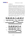
Figure 2.14 - Single output line timing (IPX-2M30-L/G)............................................................. 66
Figure 2.15 - Dual output line timing (IPX-2M30-L/G) ............................................................... 66
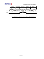
Figure 2.16 - Single / Dual Output Frame Timing (IPX-2M30-L/G) .......................................... 67
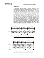
Figure 2.17 - Single Output Line Timing (IPX-2M30H-L/G) ...................................................... 68
Figure 2.18 - Dual Output Line Timing (IPX-2M30H-L/G) ....................................................... 68
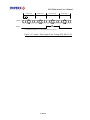
Figure 2.19 - Single / Dual Output Frame Timing (IPX-2M30H-L/G) ....................................... 69
Figure 2.20 - Single Output Line Timing (IPX-4M15-L/G) ......................................................... 70
Figure 2.21 - Dual Output Line Timing (IPX-4M15-L/G)............................................................ 70
Figure 2.22 - Single / Dual Output Frame Timing (IPX-4M15-L/G) .......................................... 71
Figure 2.23 - Single Output Line Timing (IPX-11M5-L/G) ......................................................... 72
Figure 2.24 - Dual Output Line Timing (IPX-11M5-L/G)............................................................ 72
Figure 2.25 - Single / Dual Output Frame Timing (IPX-11M5-L/G) .......................................... 73
Figure 2.26 - Single Output Line Timing (IPX-16M3-L/G) ......................................................... 74
Figure 2.27 - Dual Output Line Timing (IPX-16M3-L/G)............................................................ 75
Figure 2.28 - Single / Dual Output Frame Timing (IPX-16M3-L/G) .......................................... 75
Figure 2.29 - Horizontal and Vertical Window Positioning ......................................................... 76
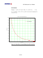
Figure 2.30 - Frame Rate vs. Vertical Window Size (IPX-VGA120-L)........................................ 78
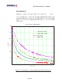
Figure 2.31 - Frame Rate vs. Vertical Window Size (IPX-VGA210-L/G).................................... 79
Figure 2.32 - Frame Rate vs. Vertical Window Size (IPX-1M48-L/G)......................................... 80
Figure 2.33 - Frame Rate vs. Vertical Window Size (IPX-2M30-L/G)......................................... 81
10 of 216
LYNX Hardware User’s Manual
Figure 2.34 - Frame Rate vs. Vertical Window Size (IPX-4M15-L/G)......................................... 82
Figure 2.35 - Frame Rate vs. Vertical Window Size (IPX-11M5-L/G)......................................... 83
Figure 2.36 - Frame Rate vs. Vertical Window Size (IPX-16M3-L/G)......................................... 84
Figure 2.37 - Horizontal and Vertical Binning ............................................................................. 85
Figure 2.38 - Electronic Shutter Position...................................................................................... 87
Figure 2.39 – Programmable Frame Rate..................................................................................... 88
Figure 2.40 - Long Integration....................................................................................................... 89
Figure 2.41a - Hardware Trigger Electrical Connection – Camera Link Output ....................... 90
Figure 2.41b - Hardware Trigger Electrical Connection – GigE Output .................................... 91
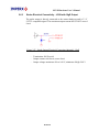
Figure 2.42 - Standard Triggering Timing .................................................................................... 93
Figure 2.43 - Fast Synchronized Triggering - Rapid Capture...................................................... 94
Figure 2.44 - Double Exposure Triggering ................................................................................... 95
Figure 2.45 - Strobe Pulse Positioning .......................................................................................... 96
Figure 2.46a - Strobe Output Electrical Connection (Internal) – Camera Link ......................... 97
Figure 2.46b – Recommended External Strobe Output Electrical Connection – ........................ 97
Camera Link.................................................................................................................................... 97
Figure 2.47 - Strobe Output Electrical Connection (Internal) - GigE ......................................... 98
Figure 2.48 - AFE Gain and Offset ............................................................................................... 99
Figure 2.49 - Data Output Format............................................................................................... 100
Figure 2.50 - Look Up Table ........................................................................................................ 101
Figure 2.51 - Gamma Corrected Video Signal ............................................................................ 102
Figure 2.52 - Custom LUT ........................................................................................................... 103
Figure 2.53 - Knee Correction...................................................................................................... 103
Figure 2.54 - Contrast Correction................................................................................................ 104
Figure 2.55 - Negative Image ....................................................................................................... 104
Figure 2.56 - Dynamic Signal-to-Noise Correction .................................................................... 107
Figure 2.57 - Normal and Mirror Image ..................................................................................... 108
Figure 2.58 - Normal and Negative Image .................................................................................. 109
Figure 2.59 - Fixed Pattern #1: Single and Dual Modes ........................................................... 112
Figure 2.60 - Fixed Pattern #2: Single and Dual Modes ........................................................... 112
Figure 2.61 – Original image showing ‘shading’ effect ............................................................. 115
Figure 2.62 – Flat Field Corrected image ................................................................................... 115
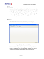
Figure 4.1 - LYNX CameraLink Interface .................................................................................. 156
11 of 216
LYNX Hardware User’s Manual
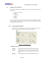
Figure 4.2 - Select Port dialog...................................................................................................... 157
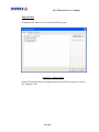
Figure 4.3 - Area of Interest Tab ................................................................................................. 159
Figure 4.4 - Triggering Tab.......................................................................................................... 161
Figure 4.5 - Video Amplifiers Tab................................................................................................ 162
Figure 4.6 - Auto Iris Tab............................................................................................................. 163
Figure 4.7 - Exposure Tab............................................................................................................ 163
Figure 4.8 - Strobe Tab................................................................................................................. 164
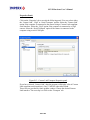
Figure 4.9 – LYNX Configurator main dialog. ........................................................................... 165
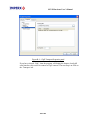
Figure 4.10 - LYNX Terminal Dialog Window. .......................................................................... 167
Figure 5.1 - LYNX GigE Interface............................................................................................... 170
Figure B.1 – LynxTerminal main dialog ..................................................................................... 190
Figure B.2 – Plug-ins panel ......................................................................................................... 191
Figure B.3 – Camera Link Transport Properties panel .............................................................. 192
Figure B.4 – GigE Transport Properties panel ........................................................................... 193
Figure B.5 – Serial Transport Properties panel .......................................................................... 194
Figure B.5 – Transport dialog...................................................................................................... 195
Figure B.6 – Loader View dialog ................................................................................................. 196
Figure B.7 –Terminal View dialog............................................................................................... 197
Figure F.1 –TEC Control Tab...................................................................................................... 212
12 of 216
LYNX Hardware User’s Manual
List of Tables
Table 1.0 - Pixel structure for different LYNX cameras. .............................................................. 20
Table 1.1 - Camera Specifications.................................................................................................. 22
Table 1.2 - Camera Output Connector – Signal Mapping ............................................................ 26
Table 1.3 - Base Camera Link bit assignment ............................................................................... 27
Table 1.4a - Camera Power Connector Pin Mapping – Camera Link Output............................. 28
Table 1.4b - BNC Connectors Pin Mapping .................................................................................. 28
Table 1.5a - Camera Power Connector Pin Mapping – GigE Output .......................................... 30
Table 1.5b - BNC Connectors Pin Mapping .................................................................................. 30
Table 2.1 - Pixel Structure and Frame Rates ................................................................................ 57
Table 2.2 - Allowable Horizontal and Window Sizes..................................................................... 77
Table A.1 – General commands ................................................................................................... 178
Table A.2 – Retrieving manufacturing data ................................................................................ 179
Table A.3 – Retrieving camera performance ............................................................................... 179
Table A.4 – Restricted commands ................................................................................................ 180
Table A.5 – Workspace ‘SET’ commands.................................................................................... 184
Table A.6 – Workspace ‘GET’ commands................................................................................... 188
Table F.1 –TEC Commands ......................................................................................................... 215
Table F.2 –TEC Variables ............................................................................................................ 216
13 of 216
LYNX Hardware User’s Manual
Chapter 1 – Introduction
Introduction
This chapter outlines the key features of the Lynx camera.
14 of 216
LYNX Hardware User’s Manual
1.1 LYNX FAMILY
The LYNX series of cameras are built around a robust imaging platform utilizing
the latest digital technology. The camera’s image processing engine is based on a 1
million gate FPGA and a 32-bit RISC processor.
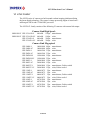
The LYNX-CL family consists of the following 22 cameras with camera link output
Camera Link High Speed:
OEM ONLY IPX-VGA120-L
OEM ONLY IPX-VGA120-LC
IPX-VGA210-L
IPX-VGA210-LC
640x480
640x480
640x480
640x480
110fps monochrome
110fps color
210fps monochrome
210fps color
Camera Link Mega-pixel:
IPX-1M48-L
IPX-1M48-LC
IPX-2M30-L
IPX-2M30-LC
IPX-2M30H-L
IPX-2M30H-LC
IPX-4M15-L
IPX-4M15-LC
IPX-4M15T-L
IPX-4M15T-LC
IPX-11M5-L
IPX-11M5-LC
IPX-11M5T-L
IPX-11M5T-LC
IPX-16M3-L
IPX-16M3-LC
IPX-16M3T-L
IPX-16M3T-LC
1000x1000
1000x1000
1600x1200
1600x1200
1920x1080
1920x1080
2048x2048
2048x2048
2048x2048
2048x2048
4000x2672
4000x2672
4000x2672
4000x2672
4872x3248
4872x3248
4872x3248
4872x3248
15 of 216
48fps
48fps
33fps
33fps
32fps
32fps
15fps
15fps
15fps
15fps
5fps
5fps
5fps
5fps
3fps
3fps
3fps
3fps
monochrome
color
monochrome
color
monochrome
color
monochrome
color
monochrome, Peltier cooled
color, Peltier cooled
monochrome
color
monochrome, Peltier cooled
color, Peltier cooled
monochrome
color
monochrome, Peltier cooled
color, Peltier cooled
LYNX Hardware User’s Manual
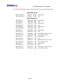
The LYNX-GigE family consists of the following 20 cameras with GigE output:
GigE High Speed:
IPX-VGA210-G
IPX-VGA210-GC
640x480
640x480
210fps monochrome
210fps color
GigE Mega-pixel:
IPX-1M48-G
IPX-1M48-GC
IPX-2M30-G
IPX-2M30-GC
IPX-2M30H-G
IPX-2M30H-GC
IPX-4M15-G
IPX-4M15-GC
IPX-4M15T-G
IPX-4M15T-GC
IPX-11M5-G
IPX-11M5-GC
IPX-11M5T-G
IPX-11M5T-GC
IPX-16M3-G
IPX-16M3-GC
IPX-16M3T-G
IPX-16M3T-GC
1000x1000
1000x1000
1600x1200
1600x1200
1920x1080
1920x1080
2048x2048
2048x2048
2048x2048
2048x2048
4000x2672
4000x2672
4000x2672
4000x2672
4872x3248
4872x3248
4872x3248
4872x3248
16 of 216
48fps
48fps
33fps
33fps
32fps
32fps
15fps
15fps
15fps
15fps
5fps
5fps
5fps
5fps
3fps
3fps
3fps
3fps
monochrome
color
monochrome
color
monochrome
color
monochrome
color
monochrome, Peltier cooled
color, Peltier cooled
monochrome
color
monochrome, Peltier cooled
color, Peltier cooled
monochrome
color
monochrome, Peltier cooled
color, Peltier cooled
LYNX Hardware User’s Manual
1.2 GENERAL DESCRIPTION
The LYNX cameras are advanced, high-resolution, progressive scan, fully
programmable and field upgradeable CCD cameras. They are built around
KODAK’s line of interline transfer CCD imagers. The camera’s image processing
engine is based on a 1 million gate FPGA and 32-bit RISC processor. The LYNX
cameras feature programmable image resolution, frame rates, gain, offset,
asynchronous external triggering with programmable exposure, fast triggering,
double exposure and capture duration, electronic shutter, long time integration,
strobe output, transfer function correction, temperature monitoring and user
programmable and up-loadable LUT. A square imager format with uniform 7.4 µm
square pixels provides for a superior image in any orientation. The interline transfer
CCD permits full vertical and horizontal resolution of high-speed shutter images.
The combination of electronic shutter and long time integration enables the cameras
capturing speed to be from 1/200,000 second to more than 10 seconds. A built-in
Gamma correction and user LUT optimizes the CCD ‘s dynamic range. The
cameras have a standard GigE or Camera Link™ interface that includes 8/10/12 bits
data transmission with one or two output taps as well as camera control and
asynchronous RS232 serial communication interface, all on a single cable. The
cameras are fully programmable via the serial interface using a GUI based
configuration utility, or optionally, the camera can be configured using simple
ASCII commands via any terminal emulator. The adaptability and flexibility of the
camera allows it to be used in a wide and diverse range of applications including
machine vision, metrology high-definition imaging and surveillance, medical and
scientific imaging, intelligent transportation systems, character recognition,
document processing and many more.
MAIN LYNX FEATURES
•
•
•
•
•
•
•
•
•
•
•
•
•
•
Interline transfer CCD
Progressive scan image
8/10/12 bit data,
Base Camera Link or GigE output
Single or Dual tap operation
RS232 serial communication
32 bit RISC processor
Horizontal and vertical binning
Dynamic transfer function correction
Dynamic S/N correction
Defective Pixel Correction
Flat Field Correction
Temperature monitor
Field upgradeable:
•
Software
•
Firmware
•
User LUTs
17 of 216
LYNX Hardware User’s Manual
•
•
Defective Pixel Map
Flat Field Coefficients
•
Highly programmable:
•
Resolution
•
Frame rate
•
Electronic shutter
•
Long integration
•
Strobe output
•
Analog gain
•
Analog offset
•
Area of interest
•
User LUT
•
Temperature alarms
•
External trigger
•
Pre-exposure
•
Fast triggering
•
Double exposure
•
Capture duration
•
•
Automatic Iris Control – optional
Peltier Cooled version available for:
o
IPX-4M15T
o
IPX-11M5T
o
IPX-16M3T
18 of 216
LYNX Hardware User’s Manual
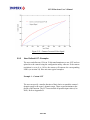
1.3 LYNX TECHNICAL SPECIFICATIONS
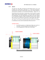
A CCD camera is an electronic device for converting light into an electrical signal.
The camera contains a light sensitive element CCD (Charge Coupled Device) where
an electronic representation of the image is formed. The CCD consists of a two
dimensional array of sensitive elements – silicon photodiodes, also known as pixels.
The photons falling on the CCD surface create photoelectrons within the pixels,
where the number of photoelectrons is linearly proportional to the light level.
Although the number of electrons collected in each pixel is linearly proportional to
the light level and exposure time, the amount of electrons varies with the
wavelength of the incident light. When the desired exposure is reached, the charges
from each pixel are shifted onto a vertical register, VCCD, and then one row
downwards in a vertical direction towards a horizontal register, HCCD. After that
the electrons contained in the HCCD are shifted in a horizontal direction, one pixel
at a time, onto a floating diffusion output node where the transformation from
charge to voltage takes place. The resultant voltage signal is buffered by a video
amplifier and sent to the corresponding video output. There are two floating
diffusions and two video amplifiers at each end of the HCCD, and the charges can
be transferred towards any of the outputs (depending on the mode of operation).
The time interval required for all the pixels, from the entire imager, to be clocked
out of the HCCD is called a frame. To generate a color image a set of color filters
(Red, Green, Blue) arranged in a “Bayer” pattern, are placed over the pixels. The
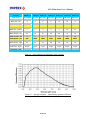
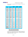
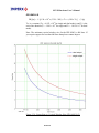
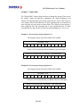
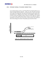
starting color is Green. Figure 1.1 shows the CCD pixel structure. Table 1.1 shows
the individual pixel structure for different LYNX cameras. Figures 1.2, 1.3 and 1.4
show the camera’s spectral response.
Figure 1.0 - CCD Pixel Structure
19 of 216
LYNX Hardware User’s Manual
Features
IPXIPXIPXIPXIPXVGA210-L/G 1M48-L/G 2M30-L/G 2M30H-L/G 4M15-L/G
IPXIPX11M5-L/G 16M3-L/G
CCD sensor
Pixel size
Black rows - top
Buffer rows - top
Active rows - (V)
Buffer rows - bottom
Black rows - bottom
Dummy pixels - left
KAI-0340S/D
7.4 μm
4
4
480
4
0
12
KAI-1020
7.4 μm
4
2
1000
2
0
8
KAI-2020
7.4 μm
2
4
1200
4
4
4
KAI-2093
7.4 μm
4
2
1080
2
4
4
KAI-4021
7.4 μm
10
6
2048
8
0
12
KAI-11002
9.0 μm
16
8
2672
8
16
4
KAI-16000
7.4 μm
4
16
3248
16
40
13
Black columns - left
24
12
16
28
28
20
28
Buffer columns - left
4
2
4
4
4
16
16
Active pixels - (H)
640
1000
1600
1920
2048
4000
4872
Buffer columns - right
4
2
4
4
4
16
16
Black columns - right
24
12
16
28
28
20
28
Dummy pixels - right
12
8
4
4
12
4
13
Frame rate - single
110 fps
30 fps
17 fps
16 fps
7.5 fps
2.5 fps
1.5 fps
Frame rate - dual
210 fps
48 fps
33 fps
32 fps
15 fps
5 fps
3 fps
Table 1.0 - Pixel structure for different LYNX cameras.
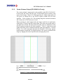
Figure 1.1 - Spectral response – monochrome quantum efficiency
(Measured with the cover glass)
20 of 216
LYNX Hardware User’s Manual
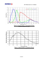
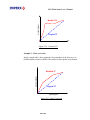
Figure 1.2 - Spectral response – color quantum efficiency
(Measured with the cover glass)
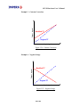
Figure 1.3 - Spectral response – UV quantum efficiency
(Measured without the cover glass)
21 of 216
LYNX Hardware User’s Manual
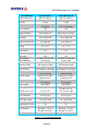
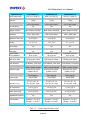
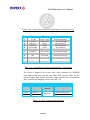
Specifications
Active image pixels
Active image area
Pixel size
Video output
IPX-VGA120-L
IPX-VGA210-L/G
640 (H) x 480 (V)
640 (H) x 480 (V)
4.74 mm x 3.55 mm
4.74 mm x 3.55 mm
7.4 μm
7.4 μm
Digital, 8/10/12 bit,
Digital, 8/10/12 bit,
one output
one or two outputs
Tap reordering
Yes
Yes
Data clock
40.000 MHz
40.000 MHz
Camera interface
Base Camera Link
Base Camera Link/GigE
RS 232 interface
Yes
Yes
Resolution
640 x 480 pixels
640 x 480 pixels
Nominal frame rate
110 fps
210 fps
Maximum frame rate
up to 900 fps
up to 3000 fps
S/N ratio
60 dB
60 dB
Binning
1 x 1, 2 x 2
1 x 1, 2 x 2
Area of interest
2 x 2 pixels min. size
2 x 2 pixels min. size
Mirror image
Yes
Yes
Negative image
Yes
Yes
Test image
Yes
Yes
Shutter speed
1/100000 to 1/100 sec
1/100000 to 1/100 sec
Long integration
Up to 10 sec
Up to 10 sec
Gamma correction
G=1.0, G=0.45, user LUT
G=1.0, G=0.45, user LUT
Black level offset
256 levels per output
256 levels per output
Video gain
6 to 40 dB per output
6 to 40 dB per output
Gain resolution
0.035 dB/step, 1024 steps 0.035 dB/step, 1024 steps
Hardware trigger
Asynchronous, active HIGH, Asynchronous, active HIGH,
optically isolated
optically isolated
Software trigger
Asynchronous, frameAsynchronous, framegrabber via CC1
grabber via CC1
Trigger modes
Normal, double exposure,
Normal, double exposure,
fast triggering
fast triggering
Strobe output
Active HIGH
Active HIGH
Camera housing
Solid, anodized aluminum
Solid, anodized aluminum
67 x 67 x 41 - CL
Size (W x H x L) mm
67 x 67 x 41
78 x 78 x 54 - GigE
Weight
280 g
280/450 g
Min. illumination
1.0 Lux, f=1.4
1.0 Lux, f=1.4
Lens Mount
C mount, 1/3” format
C mount, 1/3” format
10 V to 15 V DC
10 V to 15 V DC
Power input range
4.0 W
4.2/6.2 W
Power consumption
Yes
Yes
Upgradeable firmware
Yes
Yes
Upgradeable software
Environmental
Operating: -5 to 50 C
Operating: -5 to 50 C
Storage: -10 to 65 C
Storage: -10 to 65 C
Relative humidity
80% non-condensing
80% non-condensing
Table 1.1 - Camera Specifications
22 of 216
LYNX Hardware User’s Manual
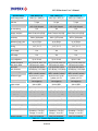
Specifications
Active image pixels
Active image area
Pixel size
Video output
IPX-1M48-L/G
IPX-2M30-L/G
IPX-2M30H-L/G
1000 (H) x 1000 (V)
1600 (H) x 1200 (V)
1920 (H) x 1080 (V)
7.40 mm x 7.40 mm
11.84 mm x 8.88 mm
14.21 mm x 7.99 mm
7.4 μm
7.4 μm
7.4 μm
Digital, 8/10/12 bit,
Digital, 8/10/12 bit,
Digital, 8/10/12 bit,
one or two outputs
one or two outputs
one or two outputs
Tap reordering
Yes
Yes
Yes
Data clock
40.000 MHz
40.000 MHz
40.000 MHz
Camera interface
Base Camera Link/GigE
Base Camera Link/GigE
Base Camera Link/GigE
RS 232 interface
Yes
Yes
Yes
Resolution
1000 x 1000 pixels
1600 x 1200 pixels
1920 x 1080 pixels
Nominal frame rate
48 fps
33 fps
33 fps
Maximum frame rate
up to 140 fps
up to 60 fps
up to 200 fps
S/N ratio
60 dB
60 dB
60 dB
Binning
1 x 1, 2 x 2
1 x 1, 2 x 2
1 x 1, 2 x 2
Area of interest
2 x 2 pixels min. size
2 x 2 pixels min. size
2 x 2 pixels min. size
Mirror image
Yes
Yes
Yes
Negative image
Yes
Yes
Yes
Test image
Yes
Yes
Yes
Shutter speed
1/50000 to 1/30 sec
1/40000 to 1/15 sec
1/35000 to 1/15 sec
Long integration
Up to 10 sec
Up to 10 sec
Up to 10 sec
Gamma correction
G=1.0, G=0.45, user LUT G=1.0, G=0.45, user LUT G=1.0, G=0.45, user LUT
Black level offset
256 levels per output
256 levels per output
256 levels per output
Video gain
0 to 36 dB per output
6 to 40 dB per output
6 to 40 dB per output
Gain resolution
0.035 dB/step, 1024 steps 0.035 dB/step, 1024 steps 0.035 dB/step, 1024 steps
Hardware trigger
Asynchronous, active
Asynchronous, active
Asynchronous, active
HIGH, optically isolated
HIGH, optically isolated
HIGH, optically isolated
Software trigger
Asynchronous, frameAsynchronous, frameAsynchronous, framegrabber via CC1
grabber via CC1
grabber via CC1
Trigger modes
Normal, double exposure, Normal, double exposure, Normal, double exposure,
fast triggering
fast triggering
fast triggering
Strobe output
Active HIGH
Active HIGH
Active HIGH
Camera housing
Solid, anodized aluminum Solid, anodized aluminum Solid, anodized aluminum
67 x 67 x 41 - CL
67 x 67 x 47 - CL
67 x 67 x 47 - CL
Size (W x H x L)
78 x 78 x 54 - GigE
78 x 78 x 60 - GigE
78 x 78 x 60 - GigE
Weight
280/450 g
310/490 g
310/490 g
Min. illumination
1.0 Lux, f=1.4
1.0 Lux, f=1.4
1.0 Lux, f=1.4
Lens Mount
C mount, 2/3” format
C mount, 1” format
C mount, 1” format
10 V to 15 V DC
10 V to 15 V DC
10 V to 15 V DC
Power input range
3.6/6.6 W
4.8/6.8 W
4.8/6.8 W
Power consumption
Yes
Yes
Yes
Upgradeable firmware
Yes
Yes
Yes
Upgradeable software
Environmental
Operating: -5 to 50 C
Operating: -5 to 50 C
Operating: -5 to 50 C
Storage: -10 to 65 C
Storage: -10 to 65 C
Storage: -10 to 65 C
Relative humidity
80% non-condensing
80% non-condensing
Table 1.1 - Camera Specifications (cont.)
23 of 216
80% non-condensing
LYNX Hardware User’s Manual
Specifications
Active image pixels
Active image area
Pixel size
Video output
IPX-4M15-L/G
2048 (H) x 2048 (V)
15.16 mm x 15.16 mm
7.4 μm
Digital, 8/10/12 bit,
one or two outputs
Tap reordering
Yes
Data clock
40.000 MHz
Camera interface
Base Camera Link/GigE
RS 232 interface
Yes
Resolution
2048 x 2048 pixels
Nominal frame rate
15 fps
Maximum frame rate
up to 115 fps
S/N ratio IPX/TEC
60/66 dB
Binning
1 x 1, 2 x 2
Area of interest
2 x 2 pixels min. size
Mirror image
Yes
Negative image
Yes
Test image
Yes
Shutter speed
1/30000 sec to 1/7 sec
Long integration
Up to 10 sec
Gamma correction
G=1.0, G=0.45, user LUT
Black level offset
256 levels per output
Video gain
6 to 40 dB per output
Gain resolution
0.035 dB/step, 1024 steps
Hardware trigger
Asynchronous, active
HIGH, optically isolated
Software trigger
Asynchronous, framegrabber via CC1
Trigger modes
Normal, double exposure,
fast triggering
Strobe output
Active HIGH
TEC Versions
Single Stage Peltier Cooler
Camera housing
Solid, anodized aluminum
Size IPX-CL (W x H x L)
67 x 67 x 47 - CL
Size IPX-G (W x H x L)
78 x 78 x 60 - GigE
Size TEC (W x H x L)
100 x 100 x 100 - TEC
Weight CL/GigE/TEC
360/520/1300 g
Min. illumination
1.0 Lux, f=1.4
Lens Mount
F mount, 22mm format
10 V to 15 V DC
Power input range
5.2/7.2/10.0 W
Power consumption
Yes
Field Upgradeable
Environmental
Operating: -5 to 50 C
Storage: -10 to 65 C
Relative humidity
80% non-condensing
IPX-11M5-L/G
4000 (H) x 2672 (V)
36.05 mm x 24.05 mm
9.0 μm
Digital, 8/10/12 bit,
one or two outputs
Yes
28.000 MHz
Base Camera Link/GigE
Yes
4000 x 2672 pixels
5 fps
up to 49 fps
60/66 dB
1 x 1, 2 x 2
2 x 200 pixels min. size
Yes
Yes
Yes
1/10000 sec to 1/3 sec
Up to 10 sec
G=1.0, G=0.45, user LUT
256 levels per output
6 to 40 dB per output
0.035 dB/step, 1024 steps
Asynchronous, active
HIGH, optically isolated
Asynchronous, framegrabber via CC1
Normal, double exposure,
fast triggering
Active HIGH
Single Stage Peltier Cooler
Solid, anodized aluminum
67 x 67 x 47 - CL
78 x 78 x 70 - GigE
100 x 100 x 100 - TEC
390/640/1350 g
1.0 Lux, f=1.4
F mount, 43mm format
10 V to 15 V DC
6.0/8.0/10.0 W
Yes
Operating: -5 to 50 C
Storage: -10 to 65 C
IPX-16M3-L/G
4872 (H) x 3248 (V)
36.05 mm x 24.05 mm
7.4 μm
Digital, 8/10/12 bit,
one or two outputs
Yes
28.000 MHz
Base Camera Link/GigE
Yes
4872 x 3248 pixels
3 fps
up to 29 fps
60/66 dB
1 x 1, 2 x 2
2 x 200 pixels min. size
Yes
Yes
Yes
1/1700 sec to 1/1.5 sec
Up to 10 sec
G=1.0, G=0.45, user LUT
256 levels per output
6 to 40 dB per output
0.035 dB/step, 1024 steps
Asynchronous, active
HIGH, optically isolated
Asynchronous, framegrabber via CC1
Normal, double exposure,
fast triggering
Active HIGH
Single Stage Peltier Cooler
Solid, anodized aluminum
67 x 67 x 47 - CL
78 x 78 x 70 - GigE
100 x 100 x 100 - TEC
470/640/1350 g
1.0 Lux, f=1.4
F mount, 43mm format
10 V to 15 V DC
6.0/8.0/10.0 W
Yes
Operating: -5 to 50 C
Storage: -10 to 65 C
80% non-condensing
80% non-condensing
Table 1.1 - Camera Specifications (cont.)
24 of 216
LYNX Hardware User’s Manual
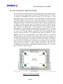
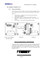
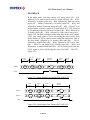
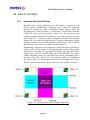
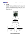
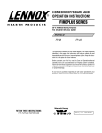
1.4 CAMERA CONNECTIVITY
1.4.1
Camera Link Output
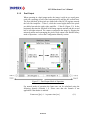
The interface between the LYNX-CL camera and outside equipment is done
via two connectors and one LED, located on the back panel of the camera –
Figure 1.4.
1.
Camera output – standard base Camera Link provides data, sync,
control, and serial interface.
10-pin Power Connector – provides power and I/O interface.
Status LED – indicates the status of the camera – refer to Status LED
section.
Serial Number – shows camera model and serial number.
2.
3.
4.
1
2
2
4
3
1
3
3
1
4
4
2
IPX-VGA / 2M30 / 2M30H-L
IPX-1M48-L
IPX-4M15-L
IPX-11M5 / 16M3-L
Figure 1.4 - Camera Back Panel – Camera Link Output
Camera data output is compliant with base Camera Link standard and includes
24 data bits, 3 sync signals (LVAL, FVAL and DVAL), 1 reference clock, 1
external input trigger CC1 and a bi-directional serial interface. The camera
link output connector is shown in Figure 1.5a, and the corresponding signal
mapping in Table 1.2.
13
1
26
14
Figure 1.5a - Camera Output Connector
25 of 216
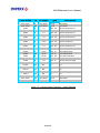
LYNX Hardware User’s Manual
Cable Name
Pin
CL Signal
Type
Description
Inner Shield
Inner Shield
- PAIR 1
+ PAIR 1
- PAIR 2
+ PAIR 2
- PAIR 3
+ PAIR 3
- PAIR 4
1
14
2
15
3
16
4
17
5
Inner Shield
Inner Shield
-X0
+X0
-X1
+X1
-X2
+X2
- X CLK
Ground
Ground
LVDS - Out
LVDS - Out
LVDS - Out
LVDS - Out
LVDS - Out
LVDS - Out
LVDS - Out
Cable Shield
Cable Shield
Camera Link
Camera Link
Camera Link
Camera Link
Camera Link
Camera Link
Camera Link
+ PAIR 4
18
+ X CLK
LVDS - Out
Camera Link Clock Tx
- PAIR 5
+ PAIR 5
+ PAIR 6
6
19
7
-X3
+X3
+ SerTC
LVDS - Out
LVDS - Out
LVDS - In
Camera Link Channel Tx
Camera Link Channel Tx
Serial Data Receiver
- PAIR 6
20
- SerTC
LVDS - In
Serial Data Receiver
- PAIR 7
8
- SerTFG
LVDS - Out
Serial Data Transmitter
+ PAIR 7
- PAIR 8
+ PAIR 8
+ PAIR 9
- PAIR 9
- PAIR 10
+ PAIR 10
+ PAIR 11
- PAIR 11
Inner Shield
21
9
22
10
23
11
24
12
25
13
+ SerTFG
- CC 1
+ CC 1
N/C
N/C
N/C
N/C
N/C
N/C
Inner Shield
LVDS - Out
LVDS - In
LVDS - In
N/C
Serial Data Transmitter
Software External Trigger
Software External Trigger
N/C
N/C
N/C
N/C
N/C
N/C
N/C
N/C
N/C
N/C
N/C
Ground
Cable Shield
Inner Shield
26
Inner Shield
Ground
Cable Shield
Channel Tx
Channel Tx
Channel Tx
Channel Tx
Channel Tx
Channel Tx
Clock Tx
Table 1.2 - Camera Output Connector – Signal Mapping
26 of 216
LYNX Hardware User’s Manual
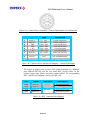
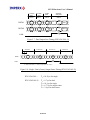
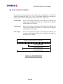
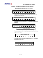
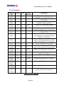
The bit assignment corresponding to the base configuration is shown in the
following table.
8-bits
Tap 1, 2
10-bits
Tap1, 2
12-bits
Tap 1, 2
A0
A1
A2
A3
A4
A5
A6
A7
A0
A1
A2
A3
A4
A5
A6
A7
A0
A1
A2
A3
A4
A5
A6
A7
A0
A1
A2
A3
A4
A5
A6
A7
DATA 8
Port B0
B0
A8
A8
DATA 9
DATA 10
DATA 11
Port B1
Port B2
Port B3
B1
B2
B3
A9
N/C
N/C
A9
A10
A11
DATA 12
Port B4
B4
B8
B8
DATA
DATA
DATA
DATA
DATA
DATA
DATA
DATA
DATA
DATA
DATA
Port
Port
Port
Port
Port
Port
Port
Port
Port
Port
Port
B5
B6
B7
N/C
B9
N/C
N/C
B0
B1
B2
B3
B4
B5
B6
B7
B9
B10
B11
B0
B1
B2
B3
B4
B5
B6
B7
Port
DATA
DATA
DATA
DATA
DATA
DATA
DATA
DATA
0
1
2
3
4
5
6
7
13
14
15
16
17
18
19
20
21
22
23
Port/bit
Port
Port
Port
Port
Port
Port
Port
Port
B5
B6
B7
C0
C1
C2
C3
C4
C5
C6
C7
N/C
N/C
N/C
N/C
N/C
N/C
N/C
ENABLE 0
LVAL
LVAL
LVAL
LVAL
ENABLE 1
ENABLE 2
ENABLE 3
CONTROL 0
CONTROL 1
CONTROL 2
FVAL
DVAL
N/C
FVAL
DVAL
N/C
FVAL
DVAL
N/C
FVAL
DVAL
N/C
CC 1
N/C
N/C
CC 1
N/C
N/C
CC 1
N/C
N/C
CC 1
N/C
N/C
CONTROL 3
N/C
N/C
N/C
N/C
Table 1.3 - Base Camera Link bit assignment
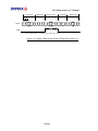
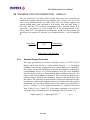
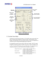
The power and all external input/output signals are supplied to the camera via
the camera power connector shown in Figure 1.5b. The corresponding pin
mapping is shown in Table 1.4a. The connector is a HIROSE type miniature
locking receptacle #HR10A-10R-10PB.
27 of 216
LYNX Hardware User’s Manual
Figure 1.5b - Camera Power Connector – Camera Link Output (viewed from rear)
Pin
Signal
Type
Description
1
2
3
4
5
6
7
8
9
Trigger In Trigger In +
GND
GND
+ 12 V
+ 12 V
Strobe Out Strobe Out +
Auto Iris +
TTL - Input
TTL - Input
Power - Input
Power - Input
Power - Input
Power - Input
TTL - Output
TTL - Output
Input
External Trigger Input
External Trigger Input
Power Ground Return
Power Ground Return
+ 12 V Power Supply
+ 12 V Power Supply
Strobe Light Sync Pulse
Strobe Light Sync Pulse
Auto Iris Feedback Input
10
Auto Iris -
Output
Auto Iris Control Output
Table 1.4a - Camera Power Connector Pin Mapping – Camera Link Output
The camera is shipped with a power cable which terminates in a HIROSE
plug #HR10A-10P-10S, and has two small BNC pig-tail cables for the
external trigger input (black) and strobe output (white). The corresponding
BNC connector pin mapping is shown on Table 1.4b.
Pin
Signal
Shield
Trigger In -
Signal
Trigger In +
Shield
Strobe Out -
Signal
Strobe Out +
Cable color
BNC Black
BNC White
Description
External Trigger Input
External Trigger Input
Strobe Light Sync Pulse
Strobe Light Sync Pulse
Table 1.4b - BNC Connectors Pin Mapping
28 of 216
LYNX Hardware User’s Manual
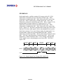
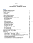
1.4.2
GigE Output
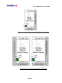
The interface between the LYNX-GigE camera and outside equipment is done
via two connectors and one LED, located on the back panel of the camera –
Figure 1.6a.
1.
2.
3.
4.
IPX-VGA / 2M30 / 2M30H-G
Camera output – standard RJ-45 provides data, sync, control, and
serial interface.
12-pin Power Connector – provides power and I/O interface.
Status LED – indicates the status of the camera – refer to Status LED
section.
Serial Number – shows camera model and serial number.
IPX-1M48-G
IPX-4M15-G
IPX-11M5 / 16M3-G
Figure 1.6a - Camera Back Panel – GigE Output
The Camera data along with the serial communication and triggering signals
are serialized and continuously transmitted over the Gigabit Ethernet interface
at GigE’s full 1-Gb/s line rate, while delivering consistently low, predictable
latencies. The network interface is compatible with IP/Ethernet networks
operating at 10/100/1000 Mb/s using standard LAN CAT-5 (CAT-5e) cables.
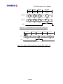
The power and all external input/output signals are supplied to the camera via
the camera power connector shown in Figure 1.6b. The corresponding pin
mapping is shown in Table 1.4b. The connector is a HIROSE type miniature
locking receptacle #HR10A-10R-12P.
29 of 216
LYNX Hardware User’s Manual
Figure 1.6b - Camera Power Connector GigE Output (viewed from rear)
Pin
Signal
Type
Description
1
- 12 V DC
Power - Input
Power Ground Return
2
+ 12 V DC
Power - Input
+ 12 V Power Supply
3
4
5
6
7
8
9
Auto Iris 1
Auto Iris 2
Auto Iris GND
Strobe GND
Strobe Out
Trigger IN
N/C
Output
Output
Ground
Ground
TTL - Output
TTL -Input
No Connect
Auto Iris Control 1
Auto Iris Control 2
Auto Iris Return
Strobe Output Return
Strobe Light Sync Pulse
External Trigger Input
Reserved for future use
10
Trigger GND
Ground
Trigger Input Return
11
N/C
No Connect
Reserved for future use
12
N/C
No Connect
Reserved for future use
Table 1.5a - Camera Power Connector Pin Mapping – GigE Output
The camera is shipped with a power cable which terminates in a HIROSE
plug #HR10A-10P-12S, and has two small BNC pig-tail cables for the
external trigger input (black) and strobe output (white). The corresponding
BNC connector pin mapping is shown on Table 1.5b
Pin
Signal
Shield
Trigger In -
Signal
Trigger In +
Shield
Strobe Out -
Signal
Strobe Out +
Cable color
BNC Black
BNC White
Description
External Trigger Input
External Trigger Input
Strobe Light Sync Pulse
Strobe Light Sync Pulse
Table 1.5b - BNC Connectors Pin Mapping
30 of 216
LYNX Hardware User’s Manual
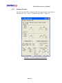
1.4.3
Power Supply
A universal desktop power supply adapter, providing +12 VDC, +/- 5%, and
up to 2.5A constant DC current, is available from Imperx for the LYNX
cameras. The operating input voltage ranges from 90 to 240 VAC.
CAUTION NOTE
1.
It is strongly recommended that you do not use an adapter other
than the one that is available from Imperx for the camera!
31 of 216
LYNX Hardware User’s Manual
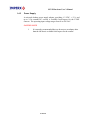
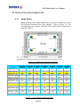
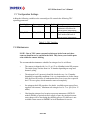
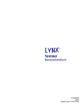
1.5 MECHANICAL, OPTICAL and ENVIRONMENTAL
1.5.1
Mechanical
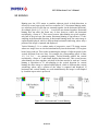
The camera housing is manufactured using high quality anodized aluminum.
For maximum flexibility the camera has eight 10-32 UNF mounting holes
(two on each side), located towards the front. An additional plate with ¼-20
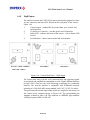
UNC (tripod mount) is shipped with each camera. Figures 1.7a and 1.7b show
the camera link cameras, Figures 1.8a and 1.8b – GigE cameras, and Figure
1.9 – Thermoelectrically (Peltier) cooled CL and GigE cameras respectively.
Figure 1.7a - C-mount camera link cameras – IPX-VGA-L / 1M48-L / 2M30-L / 2M30H -L
Figure 1.7b - F-mount camera link cameras – IPX-4M15-L / 11M5-L / IPX-16M3-L
32 of 216
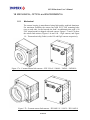
LYNX Hardware User’s Manual
Figure 1.8a - C-mount GigE cameras – IPX-VGA-G / 1M48-G / 2M30-G / 2M30H-G
Figure 1.8b - F-mount GigE cameras – IPX-4M15-G / 11M5-G / 16M3-G
33 of 216
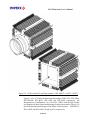
LYNX Hardware User’s Manual
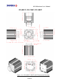
Figure 1.9 – Peltier cooled CL and GigE cameras – IPX-4M15T / 11M5T / 16M3T
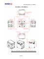
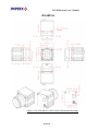
Figures 1.10 to 1.15 show the dimensional drawings of IPX-VGA, IPX-1M48,
IPX-2M30/H, IPX-4M15, IPX-11M5 and IPX-16M3 respectively. All
dimensions are in millimeters. As of 10.01.06 11M5-L and all GigE models
are shipped with black finned mid housing for better heat transfer. Figure 1.16
shows the dimensional drawings of the Peltier cooled cameras – IPX-4M15T,
IPX-11M5T and IPX-16M3T (GigE and CL) respectively.
34 of 216
LYNX Hardware User’s Manual
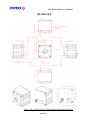
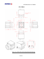
IPX-VGA120-L / IPX-VGA210-L
Figure 1.10a - IPX-VGA120-L and IPX-VGA210-L Dimensional Drawings.
35 of 216
LYNX Hardware User’s Manual
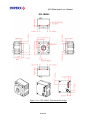
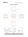
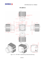
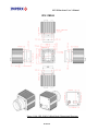
IPX-VGA210-G
Figure 1.10b - IPX-VGA210-G (Silver Body) Dimensional Drawings
36 of 216
LYNX Hardware User’s Manual
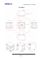
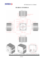
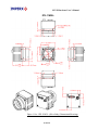
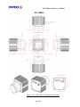
IPX-VGA210-G
Figure 1.10c - IPX-VGA210-G (Black Body) Dimensional Drawings
37 of 216
LYNX Hardware User’s Manual
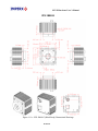
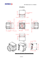
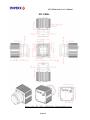
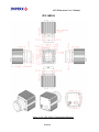
IPX-1M48-L
Figure 1.11a - IPX-1M48-L Dimensional Drawings
38 of 216
LYNX Hardware User’s Manual
IPX-1M48-G
Figure 1.11b - IPX-1M48-G (Silver Body) Dimensional Drawings
39 of 216
LYNX Hardware User’s Manual
IPX-1M48-G
Figure 1.11c - IPX-1M48-G (Black Body) Dimensional Drawings
40 of 216
LYNX Hardware User’s Manual
IPX-2M30-L / IPX-2M30H-L
Figure 1.12a - IPX-2M30-L and IPX-2M30H-L Dimensional Drawings
41 of 216
LYNX Hardware User’s Manual
IPX-2M30-G / IPX-2M30H-G
Figure 1.12b - IPX-2M30-G and IPX-2M30H-G (Silver Body) Dimensional Drawings
42 of 216
LYNX Hardware User’s Manual
IPX-2M30-G / IPX-2M30H-G
Figure 1.12c - IPX-2M30-G and IPX-2M30H-G (Black Body) Dimensional Drawings
43 of 216
LYNX Hardware User’s Manual
IPX-4M15-L
Figure 1.13a - IPX-4M15-L Dimensional Drawings
44 of 216
LYNX Hardware User’s Manual
IPX-4M15-G
Figure 1.13b - IPX-4M15-G (Silver Body) Dimensional Drawings
45 of 216
LYNX Hardware User’s Manual
IPX-4M15-G
Figure 1.13c - IPX-4M15-G (Black Body) Dimensional Drawings
46 of 216
LYNX Hardware User’s Manual
IPX-11M5-L
Figure 1.14a - IPX-11M5-L (Silver Body) Dimensional Drawings
47 of 216
LYNX Hardware User’s Manual
IPX-11M5-L
Figure 1.14b - IPX-11M5-L (Black Body) Dimensional Drawings
48 of 216
LYNX Hardware User’s Manual
IPX-11M5-G
Figure 1.14c - IPX-11M5-G (Silver Body) Dimensional Drawings
49 of 216
LYNX Hardware User’s Manual
IPX-11M5-G
Figure 1.14d - IPX-11M5-G (Black Body) Dimensional Drawings
50 of 216
LYNX Hardware User’s Manual
IPX-16M3-L
Figure 1.15a - IPX-16M3-L Dimensional Drawings
51 of 216
LYNX Hardware User’s Manual
IPX-16M3-G
Figure 1.15b - IPX-16M3-G Dimensional Drawings
52 of 216
LYNX Hardware User’s Manual
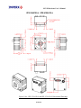
IPX-4M15T, IPX-11M5T, IPX-16M3T
Figure 1.16 – IPX-4M15T/11M5T/16M3T Dimensional Drawings
53 of 216
LYNX Hardware User’s Manual
1.5.2
Optical
The IPX-VGA, IPX-1M48, IPX-2M30 and IPX-2M30H cameras come with
an adapter for C-mount lenses, which have a 17.5 mm back focal distance.
The IPX-4M15, IPX-11M5 and IPX-16M3 cameras come with an adapter for
F-mount lenses, which have a 46.5 mm back focal distance – Figure 1.17. An
F-mount lens can be used with a C-mount camera via an F-mount to C-mount
adapter, which can be purchased separately – refer to the Imperx web side for
more information. The camera performance and signal to noise ratio depends
on the illumination (amount of light) reaching the sensor and the exposure
time. Always try to balance these two factors. Unnecessarily long exposure
will increase the amount of noise and thus decrease the signal to noise ratio.
The camera is very sensitive in the IR spectral region. If necessary, an IR filter
(1 mm thickness or less) can be inserted under the front lens bezel.
CAUTION NOTE
1.
2.
Avoid direct exposure to a high intensity light source (such as a
laser beam). This may damage the camera optical sensor!
Avoid foreign particles on the surface of the imager.
Figure 1.17 - C-mount and F-mount adapter
54 of 216
LYNX Hardware User’s Manual
1.5.3
Environmental
The camera is designed to operate from -50 to 500 C in a dry environment. The
relative humidity should not exceed 80% non-condensing. Always keep the
camera as cool as possible. Always allow sufficient time for temperature
equalization, if the camera was kept below 00 C!
The camera should be stored in a dry environment with the temperature
ranging from -100 to + 650 C.
CAUTION NOTE
1.
2.
3.
Avoid direct exposure to moisture and liquids. The camera
housing is not hermetically sealed and any exposure to liquids
may damage the camera electronics!
Avoid operating in an environment without any air circulation, in
close proximity to an intensive heat source, strong magnetic or
electric fields.
Avoid touching or cleaning the front surface of the optical
sensor. If the sensor needs to be cleaned, use soft lint free cloth
and an optical cleaning fluid. Do not use methylated alcohol!
55 of 216
LYNX Hardware User’s Manual
Chapter 2 – Camera Features
Camera Features
This chapter discusses the camera’s features and their use.
56 of 216
LYNX Hardware User’s Manual
2.1 RESOLUTION AND FRAME RATE
2.1.1
Single Output
When operating in the single output mode, all pixels are shifted out of the
HCCD register towards the left video amplifier – Video L (Figure 2.1). The
resulting image has a normal orientation, full resolution and a frame rate as
shown in Table 2.1.
Figure 2.1 - Single Output Mode of Operation
Features
IPX-VGA- IPX-1M48- IPX-2M30- IPX-2M30H- IPX-4M15- IPX-11M5- IPX-16M3210-L/G
L/G
L/G
L/G
L/G
L/G
L/G
Black rows - top
Buffer rows - top
Active rows - (V)
Buffer rows - bottom
Black rows - bottom
Dummy pixels - left
Black columns - left
Buffer columns - left
Active pixels - (H)
Buffer columns - right
4
4
480
4
0
12
24
4
640
4
4
2
1000
2
0
8
12
2
1000
2
2
4
1200
4
4
4
16
4
1600
4
4
2
1080
2
4
4
28
4
1920
4
10
6
2048
8
0
12
28
4
2048
4
16
8
2672
8
16
4
20
16
4000
16
4
16
3248
16
40
13
28
16
4872
16
Black columns - right
Dummy pixels - right
Frame rate - single
24
12
110 fps
12
8
30 fps
16
4
17
28
4
16 fps
28
12
7.5 fps
20
4
2.5 fps
28
13
1.5 fps
Frame rate - dual
210 fps
48 fps
33 fps
32 fps
15 fps
5 fps
3 fps
Table 2.1 - Pixel Structure and Frame Rates
57 of 216
LYNX Hardware User’s Manual
2.1.2
Dual Output
When operating in a dual output mode, the image is split in two equal parts,
each side consisting of half of the horizontal pixels and the full vertical lines.
The first (left) half of the pixels are shifted out of the HCCD register towards
the left video amplifier – Video L, while the second (right) half of the pixels
are shifted towards the right video amplifier – Video R (Figure 2.2). In the
horizontal direction the first half of the image appears normal and the second
half is left/right mirrored. The camera reconstructs the image by flipping the
mirrored portion and rearranging the pixels. Dual output is the default factory
mode of operation – refer to the Configuration Memory section.
Figure 2.2 - Dual Output Mode of Operation.
For normal mode of operation the frame rate can be calculated using the
following formula (Formula 1.1). Please note that the formula is not
applicable if the shutter is enabled:
Frame rate [fps] = 1 / exposure time [sec]
58 of 216
(1.1)
LYNX Hardware User’s Manual
2.1.3
Center Columns Output (IPX-VGA210-L/G only)
The ‘center columns’ output mode is only available in the IPX-VGA210-L/G.
In this mode the image field has only 228 horizontal pixels located in the
center of the imager – Figure 2.3. When operating in a single output mode, all
228 pixels are shifted out of the HCCD register towards the left video
amplifier – Video L (Figure 2.4). The resulting image has a normal orientation
and a frame rate of 289 frames per second.
When operating in a dual output mode, the image is split in two equal parts,
each having 114 pixels and full vertical lines. The frame rate in this mode is
546 frames per second. The first (left) half of the pixels are shifted out of the
HCCD register towards the left video amplifier – Video L, while the second
(right) half of the pixels is shifted towards the right video amplifier – Video R
(Figure 2.5). In the horizontal direction the first half of the image appears
normal and the second half is left/right mirrored. The camera reconstructs the
image by flipping the mirrored portion and rearranging the pixels.
Figure 2.3 - Center columns output mode of operation
59 of 216
LYNX Hardware User’s Manual
Figure 2.4 - Center Columns Output in Dual Mode of Operation
Figure 2.5 - Center Columns Output in Dual Tap Mode
60 of 216
LYNX Hardware User’s Manual
2.1.4
Timing Diagrams
IPX-VGA120-L, IPX-VGA210-L/G
In the single mode each line consists of 12 empty pixels (E1 – E12),
followed by 24 masked pixels used for black reference (R1 – R24),
followed by 4 buffer pixels (B1 – B4), followed by 640 active data
pixels (D1 – D640), followed by 4 buffer pixels (B1 – B4), and followed
by another 24 masked dark pixels (R1 – R24) – Figure 2.6.. In dual
mode each line consists of 12 empty pixels (E1 – E12), followed by 24
masked pixels used for black reference (R1 – R24), followed by 4 buffer
pixels (B1 – B4), followed by 320 active data pixels – Figure 2.7. The
data is sampled on the rising edge of the clock, and the LVAL (line
valid) signal is active only during the active pixels. Each frame (for all
modes) consists of 35.4 us vertical frame timing, followed by 4 masked
dark lines (RL1 – RL4), followed by 4 buffer lines (BL1 – BL4),
followed by 480 active lines (DL1 – DL480), and followed by 4 buffer
lines (BL1 – BL4). During each frame the FVAL (frame valid) signal is
active only during the active lines (DL1 – DL480) – Figure 2.8.
DATA
-0-
12 empty
pixels
24 dark
pixels
4 buffer
pixels
640 active
data pixels
4 buffer
pixels
24 dark
pixels
300 ns
600 ns
100 ns
16000 ns
100 ns
600 ns
E1
E12 R1
R24
B1
B4
D1
D640
B1
B4
R1
R24
-0-
LVAL
Figure 2.6 - Single Output Line Timing (IPX-VGA120/210-L and IPX-210-G)
61 of 216
LYNX Hardware User’s Manual
12 empty
pixels
24 dark
pixels
4 buffer
pixels
320 active
data pixels
300 ns
600 ns
100 ns
8000 ns
DATA 1
-0-
E1
E4
R1
R24
B1
B4
D1
D639
-0-
DATA 2
-0-
E1
E4
R1
R24
B1
B4
D2
D640
-0-
LVAL
Figure 2.7 - Dual Output Line Timing (IPX-VGA210-L/G)
4 dark lines
DATA
-0-
TL
HB
RL1
-0-
4 buffer lines
RL4
-0-
BL1
-0-
BL4
4 buffer lines
480 active lines
-0-
DL1
-0-
DL480
-0-
BL1
-0-
BL4
-0-
-0-
FVAL
TL = 8000 ns dual output; TL = 16700 ns single output; HB = 1600 ns
Figure 2.8 - Single / Dual (Center) Output Frame Timing (IPX-VGA210-L/G)
IPX-VGA120-L :
TL = 18.38 μs for single
IPX-VGA210-L/G : TL = 9.7 μs for dual
TL = 18.4 μs for single
TL = 6.73 μs for single center
TL = 3.6 μs for dual center
62 of 216
LYNX Hardware User’s Manual
IPX-VGA210-L/G – Center Columns Operation
In the center columns single mode, each line consists of 228 active data
pixels (D1 – D228), followed by 18 dark (over-clocked) pixels (R1 –
R18) – Figure 2.9. In the center columns dual mode, each line consists
of 6 masked (over-clocked) pixels (R1 – R6), followed by 114 active
data pixels – Figure 2.10.
DATA
228 active
data pixels
18 dark
pixels
5700 ns
450 ns
D1
-0-
D228
R1
R18
-0-
LVAL
Figure 2.9 - Center Columns Single Output Line Timing (IPX-VGA210-L/G)
114 active
data pixels
6 dark
pixels
2850 ns
150 ns
DATA 1
-0-
R1
R6
D1
D227
-0-
DATA 2
-0-
R1
B6
D2
D228
-0-
LVAL
Figure 2.10 - Center Columns Dual Output Line Timing (IPX-VGA210-L/G)
63 of 216
LYNX Hardware User’s Manual
IPX-1M48-L/G
In the single mode, each line consists of 8 empty pixels (E1 – E8),
followed by 12 masked pixels used for black (dark) reference (R1 –
R12), followed by 2 buffer pixels (B1, B2), followed by 1000 active
pixels (D1 – D1000), followed by 2 buffer pixels (B1, B2), and followed
by another 12 masked pixels (R1 – R12) – Figure 2.11. In the dual
mode, each line consists of 8 empty pixels (E1 – E8), followed by 12
masked pixels used for black (dark) reference (R1 – R12), followed by 2
buffer pixels (B1, B2), and followed by 500 active pixels – Figure 2.12.
The data is sampled on the rising edge of the clock, and the LVAL (line
valid) signal is active only during the active pixels. Each frame (for all
modes) consists of 61 us vertical frame timing, followed by 4 masked
lines (RL1 – RL4), followed by 2 buffer lines (BL1, BL2), followed by
1000 active lines (DL1 – DL1000). During each frame the FVAL (frame
valid) signal is active only during the active lines (DL1 – DL1000) –
Figure 2.13.
8 empty pixels
200 ns
DATA - 0 - E1
2 buffer
pixels
12 dark pixels
300 ns
50 ns
R12 B1
E8 R1
1000 active pixels
25000 ns
B2
D1
D1000
2 buffer
pixels
12 dark pixels
50 ns
300 ns
B1
B2
R1
R12
LVAL
Figure 2.11 - Single Output Line Timing (IPX-1M48-L/G)
8 empty pixels
12 dark pixels
2 buffer
pixels
300 ns
200 ns
DATA 1 - 0 - E1
E8
R1
DATA 2 - 0 - E8
E1
R12
500 active pixels
12500 ns
50 ns
R12 B1 B2
R1
B1 B2
D1
D999
-0-
D2
D1000
-0-
LVAL
Figure 2.12 - Dual Output Line Timing (IPX-1M48-L/G)
64 of 216
-0-
LYNX Hardware User’s Manual
4 dark lines
2 buffer lines
1000 active lines
2 buffer lines
TL HB
DATA
-0-
RL1
-0-
RL4
-0-
BL1
-0-
BL2
-0-
DL1
-0-
DL1000 - 0 -
BL1
-0-
BL2
-0- -0-
FVAL
TL = 13050 ns dual output; TL = 25900 ns single output; HB = 7200 ns.
Figure 2.13 - Single / Dual Output Frame Timing (IPX-1M48-L/G)
65 of 216
LYNX Hardware User’s Manual
IPX-2M30-L/G
In the single mode, each line consists of 4 empty pixels (E1 – E4),
followed by 16 masked pixels used for black (dark) reference (R1 –
R16), followed by 4 buffer pixels (B1 – B4), followed by 1600 active
data pixels (D1 – D1600), followed by 4 buffer pixels (B1 – B4), and
followed by another 16 masked dark pixels (R1 – R16) – Figure 2.14. In
the dual mode, each line consists of 4 empty pixels (E1 – E4), followed
by 16 masked pixels used for black (dark) reference (R1 – R16),
followed by 4 buffer pixels (B1 – B4), followed by 800 active data
pixels – Figure 2.15. The data is sampled on the rising edge of the clock,
and the LVAL (line valid) signal is active only during the active pixels.
Each frame consists of 82 us vertical frame timing for single mode (62
us for dual mode) followed by 2 masked dark lines (RL1, RL2),
followed by 4 buffer lines (BL1 – BL4), followed by 1200 active lines
(DL1 – DL1200), followed by 4 buffer lines (BL1 – BL4), and followed
by another 4 masked dark lines (RL1 – RL4). During each frame the
FVAL (frame valid) signal is active only during the active lines (DL1 –
DL1200) – Figure 2.16.
4 empty
pixels
100 ns
DATA
-0-
E1
E4
16 dark
pixels
4 buffer
pixels
1600 active
data pixels
4 buffer
pixels
16 dark
pixels
400 ns
100 ns
40000 ns
100 ns
400 ns
R1
R16
B1
D1
B4
D1600
B1
B4
R1
LVAL
Figure 2.14 - Single output line timing (IPX-2M30-L/G)
4 empty
pixels
100 ns
16 dark
pixels
4 buffer
pixels
800 active
data pixels
400 ns
100 ns
20000 ns
DATA 1
-0-
E1
E4
R1
R16 B1
B4
D1
D1599
-0-
DATA 2
-0-
E1
E4
R1
R16 B1
B4
D2
D1600
-0-
LVAL
Figure 2.15 - Dual output line timing (IPX-2M30-L/G)
66 of 216
R16
-0-
LYNX Hardware User’s Manual
2 dark lines
4 buffer lines
1200 active lines
4 buffer lines
4 dark lines
TL HB
DATA
-0-
RL1
-0-
RL2
-0-
BL1
-0-
BL4
-0-
DL1
-0-
DL1200 - 0 -
BL1
-0-
BL4
-0-
RL1
-0-
RL4
-0-
FVAL
TL = 20600 ns dual output; TL = 41100 ns single output; HB = 4000 ns
Figure 2.16 - Single / Dual Output Frame Timing (IPX-2M30-L/G)
67 of 216
-0-
LYNX Hardware User’s Manual
IPX-2M30H-L/G
In the single mode, each line consists of 4 empty pixels (E1 – E4),
followed by 28 masked pixels used for black (dark) reference (R1 –
R28), followed by 4 buffer pixels (B1 – B4), followed by 1920 active
data pixels (D1 – D1920), followed by 4 buffer pixels (B1 – B4), and
followed by another 28 masked dark pixels (R1 – R28) – Figure 2.17. In
the dual mode, each line consists of 4 empty pixels (E1 – E4), followed
by 28 masked pixels used for black (dark) reference (R1 – R28),
followed by 4 buffer pixels (B1 – B4), followed by 960 active data
pixels (D1 – D960) – Figure 2.18. The data is sampled on the rising
edge of the clock, and the LVAL (line valid) signal is active only during
the active pixels. Each frame consists of 90.6 us vertical frame timing
for single mode (65.9 us for dual mode), followed by 4 masked dark
lines (RL1 – RL4), followed by 2 buffer lines (BL1, BL2), followed by
1080 active lines (DL1 – DL1080), followed by 2 buffer lines (BL1,
BL2), and followed by another 4 masked dark lines (RL1 – RL4).
During each frame the FVAL (frame valid) signal is active only during
the active lines (DL1 – DL1080) – Figure 2.19.
4 empty
pixels
100 ns
DATA
-0-
E1
E4
28 dark
pixels
4 buffer
pixels
1920 active
data pixels
4 buffer
pixels
28 dark
pixels
700 ns
100 ns
48000 ns
100 ns
700 ns
R1
R28
B1
D1
B4
D1920
B1
B4
R1
LVAL
Figure 2.17 - Single Output Line Timing (IPX-2M30H-L/G)
4 empty
pixels
100 ns
28 dark
pixels
4 buffer
pixels
700 ns
100 ns
960 active
data pixels
24000 ns
DATA 1
-0-
E1
E4
R1
R28
B1
B4
DATA 2
-0-
E1
E4
R1
R28
B1
B4
D1
D1919
-0-
D2
D1920
-0-
LVAL
Figure 2.18 - Dual Output Line Timing (IPX-2M30H-L/G)
68 of 216
R28
-0-
LYNX Hardware User’s Manual
4 dark lines
2 buffer lines
1080 active lines
2 buffer lines
4 dark lines
TL HB
DATA
-0-
RL1
-0-
RL4
-0-
BL1
-0-
BL2
-0-
DL1
-0-
DL1080
-0-
BL1
-0-
BL2
-0-
RL1
-0-
RL4
-0-
FVAL
TL = 24900 ns dual output; TL = 49700 ns single output; HB = 4000 ns
Figure 2.19 - Single / Dual Output Frame Timing (IPX-2M30H-L/G)
69 of 216
-0-
LYNX Hardware User’s Manual
IPX-4M15-L/G
In single mode, each line consists of 12 empty pixels (E1 – E12),
followed by 28 masked pixels used for black (dark) reference (R1 –
R28), followed by 4 buffer pixels (B1 – B4), followed by 2048 active
data pixels (D1 – D2048), followed by 4 buffer pixels (B1 – B4), and
followed by another 28 masked dark pixels (R1 – R28) – Figure 2.20. In
the dual mode, each line consists of 12 empty pixels (E1 – E12),
followed by 28 masked pixels used for black (dark) reference (R1 –
R28), followed by 4 buffer pixels (B1 – B4), followed by 1024 active
data pixels – Figure 2.21. The data is sampled on the rising edge of the
clock, and the LVAL (line valid) signal is active only during the active
pixels. Each frame consists of 122.1 us vertical frame timing for single
mode (95.7 us for dual mode), followed by 10 masked dark lines (RL1 –
RL10), followed by 6 buffer lines (BL1 – BL6), followed by 2048 active
lines (DL1 – DL2048), and followed by 8 buffer lines (BL1 – BL8).
During each frame the FVAL (frame valid) signal is active only during
the active lines (DL1 – DL2048) – Figure 2.22.
DATA
-0-
12 empty
pixels
28 dark
pixels
4 buffer
pixels
2048 active
data pixels
4 buffer
pixels
28 dark
pixels
300 ns
700 ns
100 ns
51200 ns
100 ns
700 ns
E1
E12 R1
R28
B1
D1
B4
D2048
B1
B4
R1
R28
LVAL
Figure 2.20 - Single Output Line Timing (IPX-4M15-L/G)
12 empty
pixels
28 dark
pixels
300 ns
700 ns
4 buffer
pixels
2048 active
data pixels
100 ns
25600 ns
DATA 1
-0-
E1
E4
R1
R28
B1
B4
D1
D2047
-0-
DATA 2
-0-
E1
E4
R1
R28
B1
B4
D2
D2048
-0-
LVAL
Figure 2.21 - Dual Output Line Timing (IPX-4M15-L/G)
70 of 216
-0-
LYNX Hardware User’s Manual
10 dark lines
8 buffer lines
2048 active lines
6 buffer lines
TL HB
DATA
-0-
RL1
-0-
RL10 - 0 -
BL1
-0-
BL6
-0-
DL1
-0-
DL2048
-0-
BL1
-0-
BL8
-0-
-0-
FVAL
TL = 26700 ns dual output; TL = 53100 ns single output; HB = 4000 ns
Figure 2.22 - Single / Dual Output Frame Timing (IPX-4M15-L/G)
71 of 216
LYNX Hardware User’s Manual
IPX-11M5-L/G
In the single mode, each line consists of 4 empty pixels (E1 – E4),
followed by 20 masked pixels used for black reference (R1 – R20),
followed by 16 buffer pixels (B1 – B16), followed by 4000 active data
pixels (D1 – D4000), followed by 16 buffer pixels (B1 – B16), and
followed by another 20 masked dark pixels (R1 – R20) – Figure 2.23 In
the dual mode, each line consists of 4 empty pixels (E1 – E4), followed
by 20 masked pixels used for black reference (R1 – R20), followed by
16 buffer pixels (B1 – B16), followed by 2000 active data pixels –
Figure 2.24. The data is sampled on the rising edge of the clock, and the
LVAL (line valid) signal is active only during the active pixels. Each
frame consists of 282 us vertical frame timing for single mode (206 us
for dual mode), followed by 16 masked dark lines (RL1 – RL16),
followed by 8 buffer lines (BL1 – BL8), followed by 2672 active lines
(DL1 – DL2672), and followed by 8 buffer lines (BL1 – BL8), and
followed by 16 masked dark lines (RL1 – RL16). During each frame the
FVAL signal is active only during the active lines (DL1 – DL2672) –
Figure 2.25.
DATA
-0-
4 empty
pixels
20 dark
pixels
16 buffer
pixels
4000 active
data pixels
16 buffer
pixels
20 dark
pixels
143 ns
714 ns
572 ns
142857 ns
572 ns
714 ns
E1
E4
R1
R20
B1
D1
B16
D4000
B1
B16
R1
R20
LVAL
Figure 2.23 - Single Output Line Timing (IPX-11M5-L/G)
4 empty
pixels
143 ns
2000 active
data pixels
16 buffer
pixels
20 dark
pixels
714 ns
572 ns
71428 ns
DATA 1
-0-
E1
E4
R1
R20
B1
B16
D1
D3999
-0-
DATA 2
-0-
E1
E4
R1
R20
B1
B16
D2
D4000
-0-
LVAL
Figure 2.24 - Dual Output Line Timing (IPX-11M5-L/G)
72 of 216
-0-
LYNX Hardware User’s Manual
16 dark lines
2672 active lines
8 buffer lines
8 buffer lines
16 dark lines
TL HB
DATA
-0-
RL1
-0-
RL16
-0-
BL1
-0-
BL8
-0-
DL1
-0-
DL2672 - 0 -
BL1
-0-
BL8
-0-
RL1
-0-
RL16
-0- -0-
FVAL
TL = 145571 nssingle output; TL = 72857 ns single output; HB = 7142 ns
Figure 2.25 - Single / Dual Output Frame Timing (IPX-11M5-L/G)
73 of 216
LYNX Hardware User’s Manual
IPX-16M3-L/G
In the single mode, each line consists of 16 empty pixels (E1 – E16),
followed by 28 masked pixels used for black reference (R1 – R28),
followed by 16 buffer pixels (B1 – B16), followed by 4872 active data
pixels (D1 – D4872), followed by 16 buffer pixels (B1 – B16), and
followed by another 28 masked dark pixels (R1 – R28) – Figure 2.26 In
the dual mode, each line consists of 13 empty pixels (E1 – E13),
followed by 28 masked pixels used for black reference (R1 – R28),
followed by 16 buffer pixels (B1 – B16), followed by 2436 active data
pixels – Figure 2.27. The data is sampled on the rising edge of the clock,
and the LVAL (line valid) signal is active only during the active pixels.
Each frame consists of ? us vertical frame timing for single mode (? us
for dual mode), followed by 40 masked dark lines (RL1 – RL40),
followed by 16 buffer lines (BL1 – BL16), followed by 3248 active lines
(DL1 – DL3248), and followed by 16 buffer lines (BL1 – BL16), and
followed by 4 masked dark lines (RL1 – RL4). During each frame the
FVAL signal is active only during the active lines (DL1 – DL3248) –
Figure 2.28.
DATA
-0-
13 empty
pixels
28 dark
pixels
16 buffer
pixels
4872 active
data pixels
16 buffer
pixels
28 dark
pixels
464 ns
1000 ns
572 ns
174000 ns
572 ns
1000 ns
E1
E13 R1
R28 B1
B16
D1
D4872
B1
LVAL
Figure 2.26 - Single Output Line Timing (IPX-16M3-L/G)
74 of 216
B16
R1
R28 - 0 -
LYNX Hardware User’s Manual
13 empty
pixels
28 dark
pixels
16 buffer
pixels
2436 active
data pixels
464 ns
1000 ns
572 ns
87000 ns
DATA 1
-0-
E1
E13
R1
R28 B1
B16
D1
D4871
-0-
DATA 2
-0-
E1
E13
R1
R28 B1
B16
D2
D4872
-0-
LVAL
Figure 2.27 - Dual Output Line Timing (IPX-16M3-L/G)
40 dark lines
3248 active lines
16 buffer lines
16 buffer lines
4 dark lines
TL HB
DATA
-0-
RL1
-0-
RL40
-0-
BL1
-0-
BL16 - 0 -
DL1
-0-
DL3248 - 0 -
BL1
-0-
BL16 - 0 -
RL1
-0-
FVAL
TL = 177608 ns single output; TL = 89036 ns dual output; HB =12050 ns
Figure 2.28 - Single / Dual Output Frame Timing (IPX-16M3-L/G)
75 of 216
RL4
-0- -0-
LYNX Hardware User’s Manual
2.2 AREA OF INTEREST
2.2.1
Horizontal and Vertical Window
Horizontal and vertical windowing (Area Of Interest) is supported in all
LYNX cameras. Emphasizing a particular area of interest in horizontal
direction is possible by using a horizontal window feature, where the
beginning part of each line (pixel 1 to ‘Start Pixel’) and the end of each line
(‘End Pixel’ to Last pixel) are ignored – Figure 2.29. The precision of each
pointer (beginning and end of the window) is 1 pixel, and can be placed in the
entire image area – refer to the camera configuration section. The minimum
window size is one pixel for single mode (or 2 pixels for dual mode), and the
maximum window size is the full resolution (Last H pixel). Table 2.2 shows
the allowable values for the ‘Start Pixel’ and the ‘End Pixel’.
Emphasizing a particular area of interest in vertical direction is possible by
using a vertical window feature. Vertical windowing is used for increasing the
frame rates. For example, by skipping half of the lines, the image will be subwindowed by a factor of 2 and the frame rate will almost double. The vertical
window beginning (Start Line) and (End Line) can be programmed with a
precision of one line – Figure 2.29. The minimum window size depends on
the camera (Table 2.2), the maximum is full vertical resolution (Last V line).
Table 2.2 shows the allowable values for the ‘Start Line’ and the ‘End Line’.
Figure 2.29 - Horizontal and Vertical Window Positioning
76 of 216
LYNX Hardware User’s Manual
Feature
IPXVGA210-L
IPX1M48-L
IPXIPXIPX2M30-L 2M30H-L 4M15-L
IPX11M5-L
IPX16M3-L
Start Pixel - Min.
Start Pixel - Max.
End Pixel - Min.
1
639
2
1
999
2
1
1599
2
1
1919
2
1
2047
2
1
3999
2
1
4871
2
End Pixel - Max.
640
1000
1600
1920
2048
4000
4872
Last H Pixel
640
1000
1600
1920
2048
4000
4872
Minimum HW size
2
2
2
2
2
2
2
Start Line - Min.
Start Line - Max.
End Line - Min.
End Line - Max.
Last V Line
Recommended
Minimum VW size
1
479
2
480
480
1
999
2
1000
1000
1
1199
2
1200
1200
N/A
N/A
N/A
N/A
N/A
1
2047
2
2048
2048
1
2671
2
2672
2672
1
3247
2
3248
3248
>10
>2
>50
N/A
>100
>400
>400
Table 2.2 - Allowable Horizontal and Window Sizes
CAUTION NOTE
1.
2.
3.
4.
5.
6.
2.2.2
Horizontal and vertical windows can be enabled in all camera
modes.
The size of the horizontal window does not affect the frame rate.
The frame-grabber horizontal and vertical resolutions must be
adjusted for each window size.
a.
The horizontal resolution is equal to the window size,
which is: ‘End Pixel’ - ‘Start Pixel’ + 1.
b. The vertical resolution is equal to the window size which
is: ‘End Line’ - ‘Start Line’ + 1
Positioning the horizontal window outside the image window
will result in an error.
Color version users – for proper color reconstruction ‘Start pixel’
and ‘Start Line’ must be an odd number.
Vertical window feature is not available in IPX-2M30H-L
Calculating the Frame Rate using Vertical Window
The resulting frame rate (FR) for each camera can be approximately
calculated using formulas 2.1a – 2.1f, where WS is the window size. The
window size is the number of lines in the window (WS = ‘End Line’ – ‘Start
Line’ + 1). Figure 2.30 – 2.36 show a graphical representation of the formulas.
77 of 216
LYNX Hardware User’s Manual
IPX-VGA120-L
FR [fps] = 1 / [(0.70 x 10-6 x (492 – WS)) + TVT + (WS x TL)]
(2.1a)
TVT is a constant = 35.35 x 10⁻⁶ sec., and TL is the active line duration (TL =
18.38 x 10⁻⁶ sec).
IPX-VGA120-L FRAME RATE
1000
900
---
IPX-VGA120-L
800
Frame Rate
700
600
500
400
300
200
100
50
100
150
200
250
Active Lines
300
350
400
450
Figure 2.30 - Frame Rate vs. Vertical Window Size (IPX-VGA120-L)
78 of 216
LYNX Hardware User’s Manual
IPX-VGA210-L/G
FR [fps] = 1 / [(0.70 x 10-6 x (492 – WS)) + TVT + (WS x TL)]
(2.1b)
TVT is a constant (TVT = 35.35 x 10⁻⁶ for single and dual mode), and TL is the
active line duration (TL = 18.38 x 10⁻⁶ for single mode, TL = 9.7 x 10⁻⁶ for dual
mode, TL = 6.73 x 10⁻⁶ for single mode center, and TL = 3.6 x 10⁻⁶ for dual
mode center).
IPX-VGA210-L FRAME RATE
3000
. . . . . dual output - center
- . - . - single output - center
-------- dual output
- - - - - single output
2500
Frame Rate
2000
1500
1000
500
0
50
100
150
200
250
Active Lines
300
350
400
450
Figure 2.31 - Frame Rate vs. Vertical Window Size (IPX-VGA210-L/G)
79 of 216
LYNX Hardware User’s Manual
IPX-1M48-L/G
FR [fps] = 1 / [(7.2 x 10-6 x (1010 – WS)) + TVT + (WS x TL)]
(2.1c)
TVT is a constant (TVT = 60.90 x 10⁻⁶ for single and dual mode), and TL is the
active line duration (TL = 33.1 x 10⁻⁶ for single mode, and TL = 20.3 x 10⁻⁶ for
dual mode).
IPX-1M48-L FRAME RATE
140
-------
120
dual output
single output
Frame Rate
100
80
60
40
20
0
100
200
300
400
500
Active Lines
600
700
800
900
Figure 2.32 - Frame Rate vs. Vertical Window Size (IPX-1M48-L/G)
80 of 216
1000
LYNX Hardware User’s Manual
IPX-2M30-L/G
FR [fps] = 1 / [(4.00 x 10-6 x (1214 – WS)) + TVT + (WS x TL)]
(2.1d)
TVT is a constant (TVT = 82 x 10-6 for single mode, and TVT = 62 x 10-6 for
dual mode), and TL is the active line duration (TL = 45.18 x 10⁻⁶ for single
mode, and TL = 24.7 x 10⁻⁶ for dual mode).
IPX 2M30-L FRAME RATE
200
-------
dual output
single output
Frame Rate
150
100
50
0
0
200
400
600
Active Lines
800
1000
Figure 2.33 - Frame Rate vs. Vertical Window Size (IPX-2M30-L/G)
81 of 216
1200
LYNX Hardware User’s Manual
IPX-4M15-L/G
FR [fps] = 1 / [(4.00 x 10-6 x (2072 – WS)) + TVT + (WS x TL)]
(2.1e)
TVT is a constant (TVT = 122.1 x 10⁻⁶ for single mode, and TVT = 95.7 x 10⁻⁶
for dual mode), and TL is the active line duration (TL = 57.38 x 10⁻³ for single
mode, and TL = 30.8 x 10⁻³ for dual mode).
IPX 4M15-L FRAME RATE
120
-------
100
dual output
single output
Frame Rate
80
60
40
20
0
0
200
400
600
800
1000
1200
Active Lines
1400
1600
1800
Figure 2.34 - Frame Rate vs. Vertical Window Size (IPX-4M15-L/G)
82 of 216
2000
LYNX Hardware User’s Manual
IPX-11M5-L/G
FR [fps] = 1 / [(10.50 x 10-6 x (2720 – WS)) + TVT + (WS x TL)]
(2.1f)
TVT is a constant (TVT = 282.14 x 10⁻⁶ for single mode, and TVT = 206.07 x 10for dual mode), and TL is the active line duration (TL = 152.82 x 10⁻⁶ for
single mode, and TL = 80.14 x 10⁻⁶ for dual mode).
6
Note: The minimum vertical window size for the IPX-11M5 is 400 lines.
you require support for less than 400 lines then please contact Imperx.
Figure 2.35 - Frame Rate vs. Vertical Window Size (IPX-11M5-L/G)
83 of 216
If
LYNX Hardware User’s Manual
IPX-16M3-L/G
FR [fps] = 1 / [(1.20 x 10-5 x (3324 – WS)) + TVT + (WS x TL)]
(2.1g)
TVT is a constant (TVT = 6.952 x 10⁻⁴ for single and dual modes), and TL is the
active line duration (TL = 1.901 x 10⁻⁴ for single and TL = 1.012 x 10⁻⁴ for dual
mode).
Note: The minimum vertical window size for the IPX-16M3 is 400 lines. If
you require support for less than 400 lines then please contact Imperx.
Figure 2.36 - Frame Rate vs. Vertical Window Size (IPX-16M3-L/G)
84 of 216
LYNX Hardware User’s Manual
2.3 BINNING
Binning uses the CCD sensor to combine adjacent pixels in both directions to
effectively create larger pixels and less resolution. In 2:1 horizontal binning mode,
two adjacent pixels in each line are summed together (in the horizontal direction),
for example, pixels 1+2, 3+4, 5+6, … in each line are summed together. Horizontal
binning does not affect the frame rate. It does, however, reduce the horizontal
resolution by a factor of 2. This occurs because when binning two pixels together,
only half of the pixels per line remain. Horizontal binning is equivalent to 2:1 subsampling in the horizontal direction. In horizontal binning mode, the entire image is
captured and displayed, which is different than horizontal windowing, where only a
portion of the image is captured and displayed.
Vertical binning 2:1 is a readout mode of progressive scan CCD image sensors
where two image lines are clocked simultaneously into the horizontal CCD register
before being read out. This results in summing the charges of adjacent pixels (in the
vertical direction) from two lines. For example, the corresponding pixels in lines
1+2, 3+4, 5+6, … are summed together. Vertical binning reduces the vertical
resolution by a factor of 2, and almost doubles the frame rate. This occurs because
when binning two lines together, only half of the lines need to be read out. Vertical
binning is equivalent to 2:1 sub-sampling in the vertical direction. In vertical
binning the entire image is captured and displayed, which is different than vertical
windowing, where only a portion of the image is captured and displayed. If
horizontal and vertical binning are used simultaneously the image is sub-sampled
by 4 and the aspect ratio is preserved.
Figure 2.37 - Horizontal and Vertical Binning
85 of 216
LYNX Hardware User’s Manual
CAUTION NOTE
1.
2.
3.
4.
Horizontal or vertical binning used alone changes the aspect ratio of the
image in the vertical or horizontal direction. To correct this, use
horizontal and vertical binning simultaneously.
The frame-grabber vertical and horizontal resolution should be changed
to reflect the actual number of active pixels and lines.
Vertical binning in single output mode of operation may cause blooming
for saturated signal levels.
Color version users – horizontal or vertical binning used alone will
create color distortions. If used simultaneously, the resulting image will
be monochrome.
86 of 216
LYNX Hardware User’s Manual
2.4 EXPOSURE CONTROL
2.4.1
Electronic Shutter
During normal camera operation, the exposure time is fixed and determined
by the frame rate. The electronic shutter can be used to precisely control the
image exposure time under bright light conditions. The electronic shutter does
not affect the frame rate, it only reduces the amount of electrons collected.
The desired exposure time is set by positioning a short pulse, SHUTTER, with
respect to the vertical transfer pulse, VCCD – Figure 2.38. The electronic
shutter pulse can be positioned within the entire frame timing period with a
precision of 10 microseconds - refer to the ‘sst’ command. The minimum
shutter position is 50 microseconds.
Frame Time
Exposure
VCCD
SHUTTER
Figure 2.38 - Electronic Shutter Position
CAUTION NOTE
1.
2.
2.4.2
The electronic shutter can be enabled in all camera modes.
Positioning the shutter signal outside the frame window will
result in an error.
Variable Frame Rate – Programmable Integration
Variable frame rate mode provides the ability to run the camera in full
resolution and a frame rate slower than the nominal camera frame rate – refer
to Table 2.1. This has two effects: 1) it reduces the bandwidth requirements on
the Camera Link interface and 2) it increases the exposure time for the frame.
During normal camera operation, the nominal frame rate determines the
integration time. The desired frame rate, and thus the new integration time,
can be achieved by moving the vertical transfer pulse, VCCD, beyond the
normal integration period (the standard frame time) – Figure 2.39. The
resultant frame rate can be calculated using formula 4.1. The user can program
87 of 216
LYNX Hardware User’s Manual
the camera frame rate from 2 fps (0.5 s integration time) up to the nominal
camera speed – refer to Table 2.1, with a precision of 1.0 fps. Optionally, the
user can enter the desired frame rate in units of time instead of units of fps.
When the user the desired frame rate, the camera will calculate the
corresponding integration time. Refer to the ‘sfr’ and ‘sft’ commands for
setting the frame rate and frame time, respectively. Refer to the ‘gce’
command for retrieving the resultant exposure time. Note that the user can
reduce the exposure time by using the shutter feature – refer to the ‘sst’
command.
Frame rate [fps] = 1 / integration time [sec]
(4.1)
Programmable Integration Time
Standard Frame Time
VCCD
Figure 2.39 – Programmable Frame Rate
CAUTION NOTE
1. The maximum frame rate ( and minimum frame time ) is determined by
the camera mode of operation. If the user enters a higher frame rate than
the allowed one, the image will roll. Make sure the camera always
operates with the frame rate lower than the maximum allowed.
2. Programmable Frame Rate/Time cannot be enabled in Trigger mode.
3. Programmable Frame Rate/Time cannot be enabled in Long Integration
mode.
2.4.3
Long Integration
Long integration is used for extending the image exposure time beyond the
standard frame time. During normal camera operation, the minimum frame
rate determines the maximum exposure time. The desired exposure time can
be adjusted (increased) by moving the vertical transfer pulse, VCCD, beyond
the normal exposure range – Figure 2.40. This mode is very similar to the
variable frame rate mode except that in this mode, the shutter cannot be used.
The integration time can be programmed in 10 millisecond increments from
10 ms (camera dependent) up to 10 seconds – refer to the ‘sli’ command.
Enabling long integration reduces the frame rate. The resultant frame rate can
88 of 216
LYNX Hardware User’s Manual
be calculated using formula 4.2. This mode is displayed on the LED by slow
pulsation with a 2 second interval – refer to Status LED section.
Frame rate [fps] = 1 / long integration time [sec]
(4.2)
Long Integration Time
Standard Frame Time
VCCD
Figure 2.40 - Long Integration
CAUTION NOTE
1.
2.
3.
4.
5.
6.
During the integration time the camera has to be kept still otherwise a
motion smear will appear on the image.
The minimum value for long integration is camera dependent:
- IPX-VGA120-L – 10 ms
- IPX-VGA210-L/G – 10 ms.
- IPX-1M48-L/G – 30 ms.
- IPX-2M30/H-L/G – 70 ms.
- IPX-4M15-L/G – 120 ms.
- IPX-11M5-L/G – 420 ms.
- IPX-16M3-L/G – 680 ms.
Long Integration cannot be enabled in Trigger mode.
Long Integration cannot be enabled in Programmable Frame Rate mode.
Long Integration cannot be enabled in Shutter mode.
Long time integration significantly decreases the signal to noise ratio.
More electrons will be collected from the pixels dark current and thus
the camera noise will increase significantly.
89 of 216
LYNX Hardware User’s Manual
2.5 EXTERNAL TRIGGER
2.5.1
Triggering Inputs
In the normal mode of operation, the camera is free running. Using the
external trigger mode allows the camera to be synchronized to an external
timing pulse. There are two general modes available for external triggering –
software and hardware.
LYNX Cameras with Camera Link Output
In hardware triggering mode the camera receives the trigger signal coming
from the connector located on the back of the camera. The hardware trigger
input in LYNX with camera link output is optically isolated from the rest of
the camera hardware - Figure 2.41a. The input signals “+ TRIGGER IN” and
“– TRIGGER IN” are used to connect to an external trigger source. On the
edge of the external pulse which creates a positive voltage difference between
“+ TRIGGER IN” and “– TRIGGER IN”, a trigger signal is sent to the
camera. The voltage difference between the trigger inputs “+ TRIGGER IN”
and “– TRIGGER IN” must be positive between 3.3 and 5.0 volts. To limit the
input current a 300 ohm internal resistor is used, but the total maximum
current MUST NOT exceed 25 mA. The actual trigger pulse duration does not
affect the integration time. The minimum duration of the trigger pulse is 100
microseconds. There are no restrictions for the maximum pulse duration, but it
is recommended that the trigger pulse is kept as short as possible, especially if
a series of pulses are used.
In software triggering mode the camera receives the trigger signal coming
from the frame grabber via camera control signal CC1. In this mode, the
exposure time for the first frame can be programmed to operate in two ways:
1.
The integration time for the first frame is determined by the
value programmed in the Pre Exposure register.
2.
The integration time for the first frame is determined by the
duration of the actual CC1 trigger pulse.
+ TRIGGER IN
R1
300
TO CAMERA
25 mA MAX
- TRIGGER IN
C A M E R A
Figure 2.41a - Hardware Trigger Electrical Connection – Camera Link Output
90 of 216
LYNX Hardware User’s Manual
LYNX Cameras with GigE Output
In hardware triggering mode the camera receives the trigger signal coming
from the connector located on the back of the camera. The hardware trigger
input in LYNX with GigE output is directly connected to the camera hardware
– Figure 2.41b. The trigger signal MUST be LVTTL (3.3V) or TTL (5.0 V).
The actual trigger pulse duration does not affect the integration time. The
minimum duration of the trigger pulse is 10 microseconds. There are no
restrictions for the maximum pulse duration, but it is recommended that the
trigger pulse is kept as short as possible, especially if a series of pulses are
used.
Figure 2.41b - Hardware Trigger Electrical Connection – GigE Output
-
Termination: 200 Ω serial
Input current: minimum 0 nA; maximum 20 μA
Input voltage: maximum of low 0.9 V; minimum of high 2.1 V
In software triggering mode the camera receives the trigger signal command
from the computer, but the actual trigger pulse is generated in the camera. The
camera has a build in programmable pulse generator – refer to Appendix B –
GigE Camera Control. In this triggering mode, the exposure time for the first
frame can be programmed to operate in two ways:
1.
The integration time for the first frame is determined by the
value programmed in the Pre Exposure register.
2.
The integration time for the first frame is determined by the
value programmed in the internal pulse generator – refer to
Appendix B.
Both the hardware and software triggering modes support three sub-modes of
triggering – 1) standard, 2) rapid capture and 3) double exposure. When the
camera is programmed to operate in either of the external trigger modes, the
camera switches from free running operation to an idle mode and waits for an
external pulse. The camera behavior for the different sub-modes is described
below.
91 of 216
LYNX Hardware User’s Manual
2.5.2
Standard Triggering - Programmable Exposure
When the standard triggering mode is enabled, the camera idles and waits for
a trigger signal. Upon receiving the external trigger signal, the camera clears
the horizontal and vertical registers, sends one 5 microseconds shutter pulse to
clear the pixels and starts integration. The exposure time for the first frame
can be programmed from 10 usec to 655 msec (in 10 microseconds
increments) using the ‘spe’ (Set Pre Exposure) command. There is a fixed
additional delay of 5 usec (because of the shutter pulse) between the rising
edge of the trigger pulse and the beginning of the integration – Figure 2.42. If
the CC1 input is used - the duration of the CC1 trigger pulse can also be used
to determine the first frame exposure time. After the first frame has been
exposed, the camera is free running, where the frame rate determines the
exposure time. The number of frames captured after the trigger pulse goes
high can be programmed from 1 to 250 frames, or to be free-running – refer to
the ‘std’ command. Along with the shutter pulse, the camera sends one strobe
pulse (200 microseconds duration) for synchronization with an external
strobe. This pulse is always present in the external trigger mode, even if the
strobe is not enabled. If the strobe is enabled, there will be a second strobe
pulse during the “DATA OUT” period – refer to Figure 2.42. For more
information how to enable/disable the strobe or how to control the strobe
position refer to section 2.6.
CAUTION NOTE
1.
2.
Enabling several trigger options at the same time will result in an
error – refer to Status LED section.
For proper operation - if series of trigger pulses are used, make
sure that the timing interval between them is greater than the
corresponding frame duration – refer to section 2.1.4 Timing
Diagrams.
92 of 216
LYNX Hardware User’s Manual
TRIGGER
SHUTTER
EXPOSURE
First Frame Exposure
VCCD
FVAL
DATA
DATA Out
STROBE
Only if the strobe is enabled
Figure 2.42 - Standard Triggering Timing
2.5.3
Fast Synchronized Triggering – Rapid Capture
Fast synchronized triggering (a.k.a. rapid capture) provides the ability to run
the camera in a slave mode, allowing several cameras to be synchronized with
an external master trigger signal. This mode also enables the camera to run
close to its original frame rate. If hardware or software mode is enabled in
rapid capture mode, the camera idles and waits for a trigger signal to come
from the selected source (the external connector or CC1). Upon receiving the
trigger signal, the camera starts integration until the next trigger is received.
Then the information is transferred to the registers and read out. During this
time the next frame is exposed – Figure 2.43. Note that in this mode the
camera exposure can also be controlled with the shutter. In this triggering
mode there is no strobe pulse associated with each trigger pulse. To use the
strobe, the user must enable it – figure 2.43. For more information how to
enable/disable or control the strobe position refer to section 2.6.
CAUTION NOTE
1.
2.
The time interval between the trigger pulses must be greater than the
corresponding camera frame duration – refer to section 2.1.4 Timing
Diagrams.
If the interval between the trigger pulses is greater than 2 or 3 times the
standard frame time, it is recommended that the standard triggering
option be used.
93 of 216
LYNX Hardware User’s Manual
TRIGGER
EXPOSURE
DATA
Exposure N-1
DATA N-2
Exposure N
DATA N-1
Exposure N+1
DATA N
Exposure N+2
Exposure N+3
DATA N+1
DATA N+2
STROBE
Only if the strobe is enabled
Figure 2.43 - Fast Synchronized Triggering - Rapid Capture
2.5.4
Double Exposure Triggering
Double exposure allows two events (two images) to be captured in rapid
succession using a single trigger pulse. In this mode, the camera idles and
waits for a trigger signal to come from the selected source (the external
connector or CC1). Upon receiving the external trigger signal, the camera
clears the horizontal and vertical registers, sends one 5 microseconds shutter
pulse to clear the pixels, and starts integration. The exposure for the first
frame can be programmed from 1 usec to 65 msec (in 1 microsecond
increments) using the ‘sde’ (Set Double Exposure) command. If CC1 input is
used - the duration of the CC1 trigger pulse can also be used to determine the
first frame exposure. There is a fixed additional delay of 5 usec (because of
the shutter pulse) between the rising edge of the trigger pulse and the
beginning of the integration. Upon receiving the trigger signal the camera
starts integration for the first frame, completes the integration, transfers the
information to the vertical registers and then captures the second image. While
capturing the second image the first one is being read out. After exposing the
second image, the information is transferred to the vertical registers and read
out – Figure 2.44. The second image exposure is equal to the corresponding
camera readout time (frame duration) – refer to section 2.1.4 Timing
Diagrams. Along with the shutter pulse, the camera sends one strobe pulse
(200 microseconds duration) for synchronization with an external strobe. This
pulse is always present in the external trigger mode, even if the strobe is not
enabled. If the strobe is enabled, there will be a second and third strobe pulse
during each “DATA OUT” period – refer to Figure 2.44. For more
information how to enable/disable the strobe or how to control the strobe
position refer to section 2.6.
94 of 216
LYNX Hardware User’s Manual
CAUTION NOTE
1.
It is recommended that the minimum time duration between the events is
greater then the vertical transfer pulse duration:
a. 5 microseconds for VGA, 1M48, 2M30, 2M30H and 4M15.
b. 10 microseconds for 11M5 and 16M3.
TRIGGER
SHUTTER
EXPOSURE
DATA
Exp 1
Exposure 2
DATA 1
DATA 2
STROBE
Only if the strobe is enabled
Figure 2.44 - Double Exposure Triggering
95 of 216
LYNX Hardware User’s Manual
2.6 STROBE OUTPUT
2.6.1
Strobe Positioning
The strobe output is used to synchronize an external light source with the
camera timing, and thus to maximize the camera efficiency in low light level
conditions. The optimal strobe signal position is achieved by the positioning
of a short pulse, STROBE, (duration 200 μs) with respect to the vertical
transfer pulse VCCD - Figure 2.45. The strobe pulse can be positioned within
the entire frame timing period with a precision 10 microseconds – refer to the
‘ssp’ command.
Frame Time
Strobe Position
VCCD
STROBE
Figure 2.45 - Strobe Pulse Positioning
CAUTION NOTE
1.
2.
2.6.2
The strobe output can be enabled in all camera modes.
Positioning the strobe signal outside the frame window will
result in error – refer to Status LED section.
Strobe Electrical Connectivity – LYNX with Camera Link Output
The strobe output is optically isolated from the rest of the camera hardware.
To increase the output current to about 40 mA, the output is buffered with a
discrete transistor 2N3904 - Figure 2.46a (for GigE cameras – see Figure
2.46b). The output signals “+ STROBE” and “– STROBE” are used to
connect to an external strobe device. The actual connection depends on the
particular implementation. Figure 2.47 shows a sample wiring diagram, which
generates a 5 V strobe pulse between “+ STROBE” and “– STROBE”. The
first one (left) generates an active LOW strobe pulse, and the second one
(right) generates an active HIGH strobe pulse.
96 of 216
LYNX Hardware User’s Manual
CAUTION NOTE
1.
2.
The maximum voltage difference between the strobe outputs is 8
volts!
The maximum output current must not exceed 40mA!
R2
300
+ STROBE OUT
+ 5.0V
Q1
2N3904
- STROBE OUT
R1
1.0K
FROM CAMERA
C A M E R A
Figure 2.46a - Strobe Output Electrical Connection (Internal) – Camera Link
STROBE OUT
BNC
+ 5.0V
+ 5.0V
2
1
STROBE OUT
BNC
+ STROBE
1
+ STROBE
2
R1
1.0K
R1
1.0K
- STROBE
Strobe
Active LOW
- STROBE
Strobe
Active HIGH
Figure 2.46b – Recommended External Strobe Output Electrical Connection –
Camera Link
97 of 216
LYNX Hardware User’s Manual
2.6.3
Strobe Electrical Connectivity – LYNX with GigE Output
The strobe output is directly connected to the camera hardware and is 3.3 V
LVTTL compatible signal. The maximum output current MUST NOT exceed
8 mA.
Figure 2.47 - Strobe Output Electrical Connection (Internal) - GigE
-
Termination: 200 Ω serial
Output current: sink 8 mA; source 8 mA
Output voltage: maximum of low 0.44 V; minimum of high 2.48 V
98 of 216
LYNX Hardware User’s Manual
2.7 GAIN and OFFSET
The camera has dual analog signal processors (or Analog Front End – AFE), one
per channel. It features two independent 12 bit 40 MHz processors, each containing
a differential input sample-and-hold amplifier (SHA), digitally controlled variable
gain amplifier (VGA), black level clamp and a 12-bit ADC. The programmable
internal AFE registers include independent gain and black level adjustment. There
are 1024 possible gain levels (gcode 0 to 1023) and 256 offset (clamp) levels
(ocode 0 to 255). Figure 2.48 shows the relationship between the video signal
output level and gain/offset. Theoretically, the black level should reside at 0 volts
and the gain changes should only lead to increasing the amplitude of the video
signal. Since the camera has two separate video outputs coming out of the CCD,
there is always some offset misbalance between the video outputs. Thus, changing
the AFE gain leads to a change in the offset level and to a further misbalance
between the two video signals. To correct the balance between two signals for a
particular gain, the user should always adjust the offset for each output – refer to the
Camera Configuration section. The overall camera gain can be calculated using
formula 7.1
VGA Gain [dB] = FG [dB] + 0.0351 x gcode
(7.1)
CAUTION NOTE
1.
Increasing the gain simultaneously increases the camera noise.
2.
Fixed gain (FG) = 0 dB for IPX-1M48-L, FG = 6dB for the rest of the
cameras.
video output
AFE output
AFE gain
pixel output
black level
~ 20 mV offset
0V
light intensity
Figure 2.48 - AFE Gain and Offset
99 of 216
LYNX Hardware User’s Manual
2.8 DATA OUTPUT FORMAT
The internal camera processing of the CCD data is performed in 12 bits. The
camera can output the data in 12, 10 or 8 bit format. During this standard bit
reduction process, the least significant bits are truncated – Figure 2.49.
12 bit output:
If the 12 bit original camera data is D0 (LSB) to D11 (MSB), and
camera is set to output 12 bit data, the 12 output bits are mapped
to D0 (LSB) to D11 (MSB).
10 bit output:
If the 12 bit original camera data is D0 (LSB) to D11 (MSB), and
camera is set to output 10 bit data, the 10 output bits are mapped
to D2 (LSB) to D11 (MSB).
8 bit output:
If the 12 bit original camera data is D0 (LSB) to D11 (MSB), and
camera is set to output 8 bit data, the 8 output bits are mapped to
D4 (LSB) to D11 (MSB).
Internal Camera Processing - 12 bit Data
D0
D1
D2
D3
D4
D5
D6
D7
D8
D9
8 bit output data
10 bit output data
12 bit output data
Figure 2.49 - Data Output Format
100 of 216
D10 D11
LYNX Hardware User’s Manual
2.9 TRANSFER FUNCTION CORRECTION – USER LUT
The user defined LUT (Lookup Table) feature allows the user to modify and
transform the original video data into any arbitrary value – Figure 2.50. Any 12-bit
value can be transformed into any other 12-bit value. The camera supports two
separate lookup tables, each consisting of 2048 entries, with each entry being 12
bits wide. The first LUT is factory programmed with a standard Gamma 0.45
correction – see section 2.9.1. The second LUT is not pre-programmed in the
factory. Both LUT’s are available for modifications, and the user can generate and
upload his own custom LUT using the LynxTerminal software – refer to Appendix
B.
12 bit input
data
LUT
12 bit output
data
Figure 2.50 - Look Up Table
2.9.1
Standard Gamma Correction
The image generated by the camera is normally viewed on a CRT (or LCD)
display, which does not have a linear transfer function – i.e., the display
brightness is not linearly proportional to the scene brightness (as captured by
the camera). As the object brightness is lowered, the brightness of the display
correspondingly lowers. At a certain brightness level, the scene brightness
decrease does not lead to a corresponding display brightness decrease. The
same is valid if the brightness is increased. This is because the display has a
nonlinear transfer function and a brightness dynamic range much lower than
the camera. The camera has a built-in transfer function to compensate for this
non-linearity, which is called gamma correction. If enabled, the video signal is
transformed by a non-linear function close to the square root function (0.45
power) – formula 9.1. In the digital domain this is a nonlinear conversion
from 12-bit to 12-bit – Figure 2.51. If the camera resolution is set to 8-bit or
10-bit, the camera will truncate the corresponding LSBs (see section 2.8).
Output signal [V] = (input signal [V]) 0.45
101 of 216
(9.1)
LYNX Hardware User’s Manual
Figure 2.51 - Gamma Corrected Video Signal
2.9.2
User Defined LUT - Examples
The user can define any 12-bit to 12-bit transformation as a user LUT and can
upload it to the camera using the configuration utility software. If the camera
resolution is set to 8 or 10 bit, the camera will truncate the corresponding
LSB’s (see section 2.8). Here are some typical examples:
Example 1 – Custom LUT
The user can specify a transfer function of their choice to match the camera’s
dynamic range to the scene’s dynamic range. There are no limitations to the
profile of the function. The LUT must include all possible input values (0 to
4095). Refer to Appendix D.
102 of 216
LYNX Hardware User’s Manual
Output signal
Modified TF
Original TF
Input signal
Figure 2.52 - Custom LUT
Example 2 – Knee correction
In this example only 2 knee points have been introduced, the first one is at
(400H) and the second at (A00H). The number of knee points is not limited.
Output signal
Modified TF
Original TF
Input signal
Figure 2.53 - Knee Correction
103 of 216
LYNX Hardware User’s Manual
Output signal
Example 3 – Contrast Correction
Modified TF
Original TF
Input signal
Figure 2.54 - Contrast Correction
Example 4 – Negative Image
Output signal
Modified TF
Original TF
Input signal
Figure 2.55 - Negative Image
104 of 216
LYNX Hardware User’s Manual
Example 5 – Digital Shift
The “Digital Shift” feature allows the user to change the group of bits sent to
the camera output and therefore manipulate the camera brightness and
contrast. The internal camera processing of the data is 12 bits. If the camera is
set to output 10 bits of data then the two least significant bits are truncated. In
some cases the user may need to convert from 12 to 10 bit by preserving the 2
least significant bits and truncating the 2 most significant ones. In other
occasions the user may need to increase the image brightness 2x, 4x, 8x, etc.
Example A. Increasing the image brightness 2x:
The original camera data is D0 (LSB) to D11 (MSB)
Input Data - 12 bit
D0
D1
D2
D3
D4
D5
D6
D7
D8
D9
D10 D11
Create a LUT in which the bits are shifted by one to the right.
Modified 12 bit Output Data - (11 bit data + 1 bits shifted right)
0
D0
D1
D2
D3
D4
D5
D6
D7
D8
D9
D10
Example B. Increasing the image brightness 4x:
The original camera data is D0 (LSB) to D11 (MSB)
Input Data - 12 bit
D0
D1
D2
D3
D4
D5
D6
D7
D8
D9
D10 D11
Create a LUT in which the bits are shifted with two to the right.
Modified 12 bit Output Data - (10 bit data + 2 bits shifted right)
0
0
D0
D1
D2
105 of 216
D3
D4
D5
D6
D7
D8
D9
LYNX Hardware User’s Manual
Example C. Performing a non-standard 12 to 10 bit conversion:
The original camera data is D0 (LSB) to D11 (MSB)
Input Data - 12 bit
D0
D1
D2
D3
D4
D5
D6
D7
D8
D9
D10 D11
Create a LUT, which truncates the 2 most significant bits (bits are
shifted with two to the right).
Modified 12 bit Output Data - (10 bit data + 2 bits shifted right)
0
0
D0
D1
D2
D3
D4
D5
D6
D7
D8
D9
During the 12 to 10 bit conversion, the 2 least significant bits will be
truncated.
Modified 12 bit Output Data - (10 bit data + 2 bits shifted right)
0
0
D0
D1
D2
D3
D4
D5
D6
D7
D8
D9
10 bit output data
The camera output will be 10 bits, but in this case bits D0 to D9 are
mapped to the output.
Modified 10 bit Output Data
D0
D1
D2
D3
D4
D5
D6
D7
D8
D9
If only the standard conversion was applied, D2 to D11 would have
been mapped to the output.
Standard 10 bit Output Data
D2
D3
D4
D5
106 of 216
D6
D7
D8
D9
D10 D11
LYNX Hardware User’s Manual
DYNAMIC SIGNAL-TO-NOISE CORRECTION
As was described in the section 2.7 (Gain and Offset), the reference black level on
each CCD output fluctuates around 0V – Figure 2.56. The AFE offset correction
works on the entire image and if there are noise fluctuations on a line level, the AFE
is not capable of correcting them. The camera has a built in dynamic signal-to-noise
correction feature to compensate for this effect. In the beginning of each line the
CCD has several back (masked) columns. The dark level for each tap is sampled
over several of these masked pixels and the average per tap black level floor is
calculated for each frame. The average floor level for each tap is then subtracted
from each incoming pixel (from the corresponding tap) from the next frame.
video output
2.10
signal level
corrected
signal level
dark level
0V
masked
pixels
exposed
pixels
Figure 2.56 - Dynamic Signal-to-Noise Correction
107 of 216
LYNX Hardware User’s Manual
2.11
IMAGE REVERSAL
When operating in the image reversal mode, all pixels are shifted to the output in
the reverse order. The resultant image appears left/right mirrored in the horizontal
direction – Figure 2.57. This feature could be useful if the camera receives a
mirrored image (i.e. image coming from a mirror). In this mode the image has a
normal vertical orientation and full resolution. This feature is available in both
single and dual output modes - refer to the ‘sir’ command.
Figure 2.57 - Normal and Mirror Image
108 of 216
LYNX Hardware User’s Manual
2.12
NEGATIVE IMAGE
When operating in the negative image mode, the value of each pixel is inverted.
The resultant image appears negative – Figure 2.58. This feature could be useful if
the camera receives a negative image (i.e. image from microfilms, prints or slides).
In this mode the image has a normal vertical and horizontal orientation and full
resolution. This feature is available in both single and dual output modes – refer to
the ‘sni’ command.
Figure 2.58 - Normal and Negative Image
109 of 216
LYNX Hardware User’s Manual
2.13
CAMERA INTERFACE
2.13.1
Status LED
The camera has a green LED, located on the back panel, which indicates the
camera status and mode of operation.
• LED is steady ON – Normal operation. The user is expected to see a
normal image coming out of the camera.
• LED blinks with frequency ~ 1Hz – indicates a camera power supply
failure. This could be caused by a faulty external AC adapter.
• LED rapidly blinks with frequency ~ 5Hz – indicates camera failure
during initial setup. During camera power up this indicates an error in
the camera boot up sequence. The user is expected to see a uniform
gray screen. To restore the normal operation load the factory setting –
refer the Camera Configuration section.
• LED has one short blink every 3 seconds – Test mode. The user is
expected to see one of the test patterns.
• LED has two short blinks every 3 seconds – External or CC1 trigger
mode. The camera is waiting for a trigger input.
• LED has two short blinks every 3 seconds and then blinks rapidly –
External or CC1 trigger mode. The camera is receiving trigger pulses
and blinks at the trigger rate.
• LED has three short blinks every 3 seconds – Test mode and External
trigger mode enabled in the same time. The camera is waiting for an
external trigger input and upon receiving the signal the user will see
one of the test patterns.
• LED blinks slowly with frequency ~ 0.3Hz – Long integration mode. The
camera has to be kept steady to avoid image smear.
• LED is OFF – General error. The camera has no power or unexpected error
occurred. To restore the camera operation, re-power the camera and
load the factory settings.
2.13.2
Temperature Monitor
The camera has a built in temperature sensor which monitors the internal
camera temperature. The sensor is placed on the hottest spot in the camera.
The internal camera temperature is displayed on the Camera Configuration
Utility screen and can be queried by the user at any time. The user can also set
the alarm threshold temperature – refer to Camera Configuration section. If
the camera reaches this temperature, a message is sent via the serial port and
110 of 216
LYNX Hardware User’s Manual
the LED on the back of the camera starts to blink rapidly. The alarm is for
indication only and does not prevent the camera from continue to operate
normally.
2.13.3
Integration Time Monitor
The camera has a built in integration time monitor. In any mode of operation (
i.e. normal, AOI, binning, etc. ) the user can query the camera for the current
exposure time by issuing a ‘gce’ command. The current camera integration
time in units of microseconds will be returned.
2.13.4
Frame Rate Monitor
The camera has a built in frame rate monitor. In any mode of operation ( i.e.
normal, AOI, binning, etc. ) the user can query the camera for the current
frame rate by issuing a ‘gcs’ command. The current camera speed in units of
frames per second will be returned.
.
111 of 216
LYNX Hardware User’s Manual
2.14
TEST MODE
The camera can output three test images (two fixed and one moving), which can be
used to verify the camera’s general performance and connectivity to the frame
grabber. This ensures that all the major modules in the hardware are working
properly and that the connection between the frame grabber and the camera is
synchronized (i.e., the camera parameters: # pixels, # lines, # bits, output mode,
communication rate, etc. are properly configured). Figure 2.59 shows a diagonal
gray scale variation for single and dual modes. Figure 2.60 shows gray scale
vertical bars for single and dual modes. The motion test pattern is a diagonal gray
scale variation similar to test pattern #1. The motion is in the vertical direction. The
test mode does not exercise and verify the CCD’s functionality.
Figure 2.59 - Fixed Pattern #1: Single and Dual Modes
Figure 2.60 - Fixed Pattern #2: Single and Dual Modes
112 of 216
LYNX Hardware User’s Manual
2.15
AUTOMATIC IRIS CONTROL
The camera has an optional auto iris control feature. If enabled, the camera
calculates the average image brightness within the frame and compares it to a user
specified threshold level – refer to the ‘sai’ command. If the calculated brightness
level is less then the threshold, the camera sends a signal to open the lens iris. If the
brightness level is more than the threshold, the camera sends a signal to close the
iris. The camera iris control hardware is compatible only with DC type auto iris
lenses.
2.16
DEFECTIVE PIXEL CORRECTION
All CCD sensors have some number of defective pixels. A defective pixel is
defined as a pixel whose response deviates by more than 15% from the average
response. In extreme cases these pixels can be stuck ‘black’ or stuck ‘white’ and are
non-responsive to light. During factory final testing, our manufacturing engineers
run a program specially designed to identify these ‘defective’ pixels. The program
creates a file which lists the coordinates ( i.e. row and column ) of every defective
pixel. This file, called the Defect Pixel Map, is then downloaded into the camera’s
non-volatile memory. When ‘Defective Pixel Correction’ is enabled, the camera
will compare each pixel’s coordinates with entries in the ‘defect’ map. If a match is
found, then the camera will ‘correct’ the defective pixel. Defective Pixel Correction
is enabled by issuing an ‘sdc on’ ( Set Defect Correction – On ) command. The
camera will display the contents of the Defect Pixel Map when the user issues a
‘dpm’ ( Dump Pixel Map ) command.
113 of 216
LYNX Hardware User’s Manual
2.17
FLAT FIELD CORRECTION
A CCD imager is composed of a two dimensional array of light sensitive pixels.
Each pixel within the array, however, has its own unique light sensitivity
characteristics. Most of the deviation is due to the difference in the angle of
incidence and to charge transport artifacts. This artifact is called ‘Shading’ and in
normal camera operation should be removed. The process by which a CCD camera
is calibrated for shading is known as ‘Flat Field Correction’. Refer to Figures 2.61
and 2.62 for images acquired before and after Flat Field Correction.
The Lynx series of cameras incorporate a Flat Field Correction mechanism. The
Flat Field Correction mechanism measures the response of each pixel in the CCD
array to illumination and is used to correct for any variation in illumination over the
field of the array. The optical system most likely introduces some variation in the
illumination pattern over the field of the array. The flat field correction process
compensates for uneven illumination, if that illumination is a stable characteristic of
each object exposure.
During factory final testing, our manufacturing engineers run a program specially
designed to identify the shading characteristics of the camera. The program creates
a Flat Field Correction file, which contains coefficients describing these shading
characteristics. This file is then downloaded into the camera’s non-volatile memory.
When Flat Field Correction is enabled, the camera will use the Flat Field Correction
coefficients to compensate for the shading effect. Flat Field Correction is enabled
by the user issuing an ‘sfc on’ ( Set Flatfield Correction – On ) command.
Each Imperx camera is shipped with the Flat Field Correction file that was created
for that camera during factory final testing. Users may wish, however, to create
their own Flat Field Correction file because of the uniqueness of their operating
environment ( i.e. lens, F-stop, lighting, etc. ). Therefore, Imperx provides a Flat
Field Correction utility that allows users to generate a Flat Field Correction file.
This file can then be downloaded into the camera. While creating the Flat Field
Correction file, it is necessary to illuminate the CCD with a light pattern that is as
representative of the background illumination as possible. This illumination should
be bright enough, or the exposure made long enough, so that the CCD pixels signals
are at least 25 percent of full scale ( for 12 bit mode the level should be at least
1000 ADUs ). Please refer to application note ‘AN-L04’ for details on how to create
a Flat Field Correction file.
NOTE: Flat Field Correction is supported only in the IPX-2M30, IPX-2M30H,
IPX-4M15, IPX-11M5 and IPX-16M3 cameras.
114 of 216
LYNX Hardware User’s Manual
Figure 2.61 – Original image showing ‘shading’ effect
Figure 2.62 – Flat Field Corrected image
115 of 216
LYNX Hardware User’s Manual
2.18
THERMO-ELECTRIC COOLING ( TEC )
Active cooling of the CCD-imager through solid state thermoelectric cooler ( Peltier
element ) is available on the IPX-4M15T, IPX-11M5T and IPX-16M3T cameras.
The CCD imager is cooled to several degrees below ambient compared to ambient
plus 20 degC ( approximately ) for the uncooled cameras. The exact CCD
temperature varies with camera model due to the difference in imager size and
available power for the cooler.
The cooler is based on a single stage Peltier thermoelectric element driven by an
electronic control circuit which controls the current/power flowing into the cooler
while monitoring the CCD temperature. The cooler acts like a heat pumping device,
removing heat from the CCD and dissipating it through the external
heatsink/housing. The cooler requires additional power to remove heat. Every watt
of heat removed requires about one watt of operating power. For this reason the
TEC cooled cameras require a larger heatsink/housing to dissipate the additional
heat generated ( heat removed + input power ). The additional power dissipated
ranges from 5W to 15W depending on camera model and operating conditions.
Because the CCD imager operates below ambient and because the temperature can
approach 0 degC the CCD chamber has to be sealed and filled with dry nitrogen to
prevent the formation of condensation on the imager. The nitrogen charge needs to
be checked periodically ( annually ) or whenever condensation occurs. Refer to the
Imperx “TEC Nitrogen-check/purge/refill” application note for details. The camera
should not be exposed to extreme pressure and temperature changes to prevent the
loss of Nitrogen from the CCD chamber. Consult Imperx for details
TEC cooled cameras require between 1A and 3A of current at 12Vdc depending on
camera model and operating mode/condition which has to be considered when
camera is not powered from the supplied AC/DC adapter.
116 of 216
LYNX Hardware User’s Manual
Chapter 3 – Camera Configuration
Camera Configuration
This chapter discusses how to configure the camera’s operating
parameters.
117 of 216
LYNX Hardware User’s Manual
3.1 Overview
The Lynx series of cameras are highly programmable and flexible. All of the
camera’s features and operating parameters can be controlled by the user. The user
communicates with the camera using simple ASCII commands via the Camera
Link’s serial interface. All of the cameras resources (internal registers, video
amplifiers and EEPROM) can be configured and monitored via this interface. The
format of the serial interface is ASYNC with 8 data bits, 1 stop bit, no parity and no
handshake. The interface operates at a rate of 9,600 bps. The interface is bidirectional with the user issuing ‘commands’ to the camera and the camera issuing
‘responses’ (either status or info) to the user. The camera’s parameters can be
programmed using the Lynx Configurator graphical user interface or via simple
ASCII commands using the Lynx Terminal utility or any terminal emulator.
118 of 216
LYNX Hardware User’s Manual
3.2 Configuration Memory
The camera has a built-in configuration memory divided into 4 segments: ‘workspace’, ‘factory-space’, ‘user-space #1’ and ‘user-space #2’. The ‘work-space’
segment contains the current camera settings while the camera is powered-up and
operational. All camera registers are located in this space. These registers can be
programmed and retrieved via commands issued by the user. The workspace is
RAM based and upon power down all camera registers are cleared. The ‘factoryspace’ segment is ROM based, write protected and contains the default camera
settings. This space is available for read operations only. The ‘user-space #1’ and
‘user-space #2’ are non-volatile, EEPROM based and used to store two user defined
configurations. Upon power up, the camera firmware loads the work-space registers
from either the factory-space, user-space #1 or user-space #2 as determined by a
‘boot control’ register located in the configuration memory. The ‘boot control’
register can be programmed by the user (refer to Camera Configuration Section)
with the ‘sbf’ command. The user can, at any time, instruct the camera to loads its
workspace with the contents of either the ‘factory-space’, ‘user-space #1’ or ‘userspace #2’. Similarly, the user can instruct the camera to save the current workspace
settings into either the ‘user-space #1’ or ‘user-space #2’.
119 of 216
LYNX Hardware User’s Manual
3.3 Command Format
Command strings consist of a command token followed by up to two parameters.
The format of the command string is:
<command> <parm1> <parm2><cr>
In response to the receipt of a command string, the camera will perform the
intended operation and return a response string. Depending on the type of command
received, the camera will return either a ‘status’ response or an ‘info’ response. A
‘status’ response generally reports the success or failure of the camera to perform
the commanded operation. An ‘info’ response provides specific camera information
requested by user.
The format of the status response string is:
OK<cr><lf>:
if the command was processed properly.
Error: <text><cr><lf>:
if the command was not processed due to an
error, where <text> is an explanation of the
error.
The format of the info response string is:
<response><cr><lf>:
see the following sections for details of the
<response> string.
Important Note: The following applies to software versions 1.57 and lower.
Escape markers were removed from software version 1.58 and higher.
All camera responses are enclosed within a pair an Escape Markers. An Escape Marker
consists of a 6 character string as follows:
<ESC>[<CODE1><CODE2><CODE3><CODE4>
Byte1 = 1B hex ( ESC character )
Byte2 = 5B hex ( [ character )
Byte3-6 = marker codes
For example, in response to a ‘gag 1’ command the camera will return ( in hex ):
67 61 67 20 31 20 0D 0A 1B 5B A1 00 00 00 0D 0A 31 34 2E 39 37 64 42 0D 0A 1B 5B A2 00 00 00 0D 0A 3A 20
gag 1 ( if echo is on ) Escape Marker
14.97 dB
Escape Marker
:
Escape Markers are used during camera download and should be ignored otherwise.
Terminal emulator programs ( i.e. HyperTerminal ) are designed to ignore Escape
Markers.
120 of 216
LYNX Hardware User’s Manual
3.4 Command Help
The camera will return a list of available commands when the user enters the ‘h’
command.
For command specific help, enter ‘h <cmd>’, and the camera will display the
command definition and syntax. For example, entering ‘h svw’ yields:
Set vertical window
Syntax: svw {y1 y2}
121 of 216
LYNX Hardware User’s Manual
3.5 Startup procedure
Upon power on or receipt of an ‘rc’ command, the camera performs the following
steps:
1.
The RISC processor runs and executes code from internal read only
memory.
2.
The boot loader code sends the string:
“Boot loader version x.y running…”.
3.
Boot loader checks FLASH memory for a valid software application.
4.
If a valid software application is not found, the boot loader waits for the user
to perform a software download ( refer to Appendix B ) and sends the string:
“No FLASH image found…waiting for software download
command”
5.
If a valid software application is found, the application program is copied
from FLASH to SRAM and the RISC processor start executing it.
6.
The camera sends a string that contains the camera type ( read from the
EEPROM’s manufacturing data area ), boot loader’s revision number,
software application’s revision number and firmware’s revision number.
For example:
‘IPX-1M48-L – SW v2.0 - BL v1.0 - FW v1.5’
7.
The camera reads the ‘Boot From’ variable from the EEPROM and sends
one of the following strings as determined by the ‘Boot From’ variable:
‘Loading from Factory…’
‘Loading from User #1…’
‘Loading from User #2…’
8.
The camera loads its workspace from one of the configuration spaces by
performing a ‘lff’, ‘lfu 1’ or ‘lfu 2’ command.
9.
The camera sends an ‘OK<cr><lf>:’ string and is ready to accept user
commands.
122 of 216
LYNX Hardware User’s Manual
3.6 Saving and Restoring Settings
Operational settings for the camera may be stored for later retrieval in its nonvolatile memory. Three separate configuration spaces exist for storing these
settings: ‘factory’ space, ‘user #1’ space and ‘user #2’ space. The factory space is
pre-programmed by factory personnel during the manufacturing process. This space
is write protected and cannot be altered by the user. Two user spaces are also
provided allowing the user to store his/her own preferences. The camera can be
commanded to load its internal workspace, from either of the three configuration
spaces, at any time. The user can also define from which space the camera should
automatically load itself following a power cycle or receipt of a reset (‘rc’)
command.
3.6.1
Set Boot From (‘sbf’)
The ‘sbf’ command determines which configuration space (factory, user#1
or user #2) should be loaded into the camera following a power cycle or reset
(‘rc’) command. This command sets a ‘boot from’ variable that is saved in
non-volatile memory. Upon a power cycle or reset, the camera reads the ‘boot
from’ variable from non-volatile memory and loads the appropriate
configuration space.
3.6.2
Syntax:
sbf <f|u1|u2>
Parameter #1:
f
u1
u2
Factory configuration space.
User #1 configuration space.
User #2 configuration space.
Example:
sbf u1
Sets the ‘boot from’ variable to user #1.
Get Boot From (‘gbf’)
The ‘gbf’ command returns the current state of the ‘boot from’ variable.
3.6.3
Syntax:
gbf
Response:
f|u1|u2
Example:
gbf
u1
User enters command.
Camera responds with current settings.
Load From Factory (‘lff’)
The ‘lff’ command instructs the camera to load its workspace from the
factory space. All current workspace settings will be replaced with the
contents of the factory space.
Syntax:
lff
123 of 216
LYNX Hardware User’s Manual
3.6.4
Load From User (‘lfu’)
The ‘lfu’ command instructs the camera to load its workspace from one of
the two user spaces. All current workspace settings will be replaced with the
contents of the selected user space.
Syntax:
lfu <1|2>
Parameter #1:
1
User #1 configuration space.
2
User #2 configuration space.
lfu 2
Camera loads workspace from user #2
space.
Example:
3.6.5
Save To Factory (‘stf’)
The ‘stf’ command instructs the camera to save all of the current workspace
settings into the factory space.
Syntax:
Note:
3.6.6
stf
This command can only be executed in supervisor mode. It is
intended for use by factory personnel only.
Save To User (‘stu’)
The ‘stu’ command instructs the camera to save all of the current workspace
settings into the selected user space.
Syntax:
stu <1|2>
Parameter #1:
1
2
User #1 configuration space.
User #2 configuration space.
Example:
stu 1
Camera saves workspace into user #1
space.
124 of 216
LYNX Hardware User’s Manual
3.7 Retrieving Manufacturing Data
The camera contains non-volatile memory that stores manufacturing related
information. This information is programmed in the factory during the
manufacturing process.
3.7.1
Get Manufacturing Data (‘gmd’)
The ‘gmd’ command returns a listing of all manufacturing data.
3.7.2
Syntax:
gmd
Response:
Camera responds with complete manufacturing data.
Example:
Assembly Part #:
Assembly Serial #:
CCD Serial #:
Date of Mfg:
Camera Type:
ASSY-0044-0001-RA01
010009
018075
12/17/03
IPX-1M48-L
Get Assembly Number (‘gan’)
The ‘gan’ command returns the camera’s assembly number.
3.7.3
Syntax:
gan
Response:
Camera responds with its assembly number.
Example:
ASSY-0044-0001-RA01
Get Model Number (‘gmn’)
The ‘gmn’ command returns the camera’s model number.
3.7.4
Syntax:
gmn
Response:
Camera responds with its model number.
Example:
IPX-1M48-L
Get Firmware Version (‘gfv’)
The ‘gfv’ command returns the camera’s firmware version.
Syntax:
gfv
Response:
Camera responds with its firmware version and
customer ID ( for custom firmware ).
Example:
FW v1.3 CUST 5
125 of 216
LYNX Hardware User’s Manual
3.7.5
Get Software Version (‘gsv’)
The ‘gsv’ command returns the camera’s software version.
Syntax:
gsv
Response:
Camera responds with its software version, bootloader
version and customer ID ( for custom software ).
Example:
SW v1.0 BL v2.0 CUST 4
126 of 216
LYNX Hardware User’s Manual
3.8 Command Description
3.8.1
Horizontal Window
3.8.1.1
Set Horizontal Window (‘shw’)
The ‘shw’ command sets the horizontal area of interest. The camera will
deliver to the Camera Link interface, per line, only the range of pixels
specified by this command. This command programs the camera with
the starting and ending pixel but does not turn on windowing. In order to
enable windowing, the ‘shm w’ command must be issued.
Syntax:
shw <x1> <x2>
Parameter #1:
x1
The first pixel in the line.
Parameter #2:
x2
The last pixel in the line.
Range:
x1
min=1, max=camera dependent
x2
min=1, max=camera dependent
Example: shw 100 500
Notes:
3.8.1.2
Sets the horizontal window from pixel#
100 to pixel# 500.
When using this command it is necessary to adjust the
number of active pixels per line in the frame grabber to
the value: x2-x1+1.
Get Horizontal Window (‘ghw’)
The ‘ghw’ command returns the current horizontal area of interest
setting.
Syntax:
ghw
Response:
x1 x2
Example:
ghw
100 500
127 of 216
User enters command.
Camera responds with current settings.
LYNX Hardware User’s Manual
3.8.2
Vertical Window
3.8.2.1
Set Vertical Window (‘svw’)
The ‘svw’ command sets the vertical area of interest. The camera will
deliver to the Camera Link interface, per frame, only the range of lines
specified by this command. Using this command increases the effective
frame rate of the camera and also reduces the automatic exposure time (
when shutter is disabled ). This command programs the camera with the
starting and ending line but does not turn on windowing. In order to
enable windowing, the ‘svm w’ command must be issued.
Syntax:
svw <y1> <y2>
Parameter #1:
y1
The first line in the image.
Parameter #2:
y2
The last line in the image.
Range:
y1
y2
min=1, max=camera dependent
min=1, max=camera dependent
Example: svw 10 120
Notes:
3.8.2.2
Sets the vertical window from line# 10
to line# 120.
When using this command it is necessary to adjust the
number of active lines in the frame grabber to the value:
y2-y1+1.
Get Vertical Window (‘gvw’)
The ‘gvw’ command returns the current vertical area of interest setting.
Syntax:
gvw
Response:
y1 y2
Example:
gvw
10 120
128 of 216
User enters command.
Camera responds with current settings.
LYNX Hardware User’s Manual
3.8.3
Shutter Time
3.8.3.1
Set Shutter Time (‘sst’)
The ‘sst’ command sets the shutter timing.
Syntax:
sst <off|i>
Parameter:
off
i
Disables the shutter mode.
The shutter time in units of uSeconds.
Range:
i
min=50
max=the lesser of 500,000 or 1/frame rate
3.8.3.2
Example:
sst 80
Notes:
The shutter operates in increments of 10 uSeconds and
therefore will round the least significant digit entered.
Sets the shutter time to 80 uSeconds.
Get Shutter Time (‘gst’)
The ‘gst’ command returns the current shutter setting.
Syntax:
gst
Response:
off|i
Example:
gst
80
129 of 216
User enters command.
Camera responds with current setting.
LYNX Hardware User’s Manual
3.8.4
Long Integration
3.8.4.1
Set Long Integration (‘sli’)
The ‘sli’ command sets the long integration timing.
3.8.4.2
Syntax:
sli <off|i>
Parameter:
off
i
Disables the long integration mode.
The long integration time in units of
mSeconds.
Range:
i
min=10 max=10,000
Example:
sli 750
Sets the long integration time to 750
msecs.
Notes:
Long integration operates in increments of 10
mSeconds and therefore will round the least significant
digit entered.
Get Long Integration (‘gli’)
The ‘gli’ command returns the current long integration setting.
Syntax:
gli
Response:
off|i
Example:
gli
750
130 of 216
User enters command.
Camera responds with current setting.
LYNX Hardware User’s Manual
3.8.5
Strobe Position
3.8.5.1
Set Strobe Position (‘ssp’)
The ‘ssp’ command sets the position of the strobe pulse output. The
strobe pulse position is set relative to the end of the frame.
Syntax:
ssp <off|i>
Parameter:
off
i
Disables the strobe.
The strobe position in units of uSeconds.
Range:
i
min=10
max=the lesser of 500,000 or 1/frame rate
3.8.5.2
Example:
ssp 120
Notes:
The strobe operates in increments of 10 uSeconds and
therefore will round the least significant digit entered.
Sets the strobe position to 120 uSeconds.
Get Strobe Position (‘gsp’)
The ‘gsp’ command returns the current long integration setting.
Syntax:
gsp
Response:
off|i
Example:
gsp
120
131 of 216
User enters command.
Camera responds with current setting.
LYNX Hardware User’s Manual
3.8.6
Analog Gain
3.8.6.1
Set Analog Gain (‘sag’)
The ‘sag’ command sets the analog gain of the camera.
Syntax:
sag <0|1|2> <i> <j>
Parameter #1:
0
1
2
Sets both taps to the same gain or to
different gains.
Selects tap #1.
Selects tap #2.
Parameter #2:
i
The tap #1 gain setting in dB.
Parameter #3:
j
The tap #2 gain setting in dB.
Range:
i,j
min=6, max=40
Examples:
sag 2 12
Sets the gain for tap #2 to 12 dB.
sag 0 12
Sets both tap gains to 12 dB.
sag 0 10 12
Sets tap#1 gain to 10 dB and tap #2
gain to 12 dB.
Notes:
The gain can be adjusted in increments of .3 dB.
With ‘sag 0’ both taps are affected. If only one
parameter is provided then both taps are set to the same
value. If two parameters are provided, then both taps
can be set to different values.
3.8.6.2
Get Analog Gain (‘gag’)
The ‘gag’ command returns the current analog gain settings.
Syntax:
gag <0|1|2>
Parameter:
0
1
2
Response:
tap#1_gain tap#2_gain
Example:
gag 2
12
132 of 216
Selects both taps.
Selects tap #1.
Selects tap #2.
User enters command to get gain for tap #2.
Camera responds with current setting.
LYNX Hardware User’s Manual
3.8.7
Analog Offset
3.8.7.1
Set Analog Offset (‘sao’)
The ‘sao’ command sets the analog offset of the camera.
Syntax:
sao <0|1|2> <i> <j>
Parameter #1:
0
1
2
Sets both taps to the same offset or to
different offsets.
Selects tap #1.
Selects tap #2.
Parameter #2:
i
The tap #1 offset setting.
Parameter #3:
j
The tap #2 offset setting.
Range:
i,j
min=0, max=255
Examples:
sao 2 64
Sets the offset for tap #2 to 64.
sao 0 64
Sets both tap offsets to 64.
sao 0 32 48
Sets tap #1 offset to 32 and tap #2
offset to 48.
3.8.7.2
Get Analog Offset (‘gao’)
The ‘gao’ command returns the current analog offset settings.
Syntax:
gao <0|1|2>
Parameter:
0
1
2
Response:
tap#1_offset tap#2_offset
Example:
gao 0
32 48
133 of 216
Selects both taps.
Selects tap #1.
Selects tap #2.
User enters command to get offset for both
taps.
Camera responds with both current
settings.
LYNX Hardware User’s Manual
3.8.8
Dual Tap mode
3.8.8.1
Set Dual Mode (‘sdm’)
The ‘sdm’ command sets the camera to operate in either single or dual
tap mode.
3.8.8.2
Syntax:
sdm <on|off>
Parameter:
on
off
Selects dual tap operation.
Selects single tap opertion.
Example:
sdm on
Enables dual tap operation.
Get Dual Mode (‘gdm’)
The ‘gdm’ command returns the current dual tap mode setting.
Syntax:
gdm
Response:
on|off
Example:
gdm
on
134 of 216
User enters command.
Camera responds with current setting.
LYNX Hardware User’s Manual
3.8.9
Bit Depth
3.8.9.1
Set Bit Depth (‘sbd’)
The ‘sbd’ command sets the bit depth of the camera.
3.8.9.2
Syntax:
sbd <8|10|12>
Parameter:
8
10
12
Selects 8 bit operation.
Selects 10 bit operation.
Selects 12 bit operation.
Example:
sbd 10
Enables 10 bit operation.
Get Bit Depth (‘gbd’)
The ‘gbd’ command returns the current bit depth setting.
Syntax:
gbd
Response:
8|10|12
Example:
gbd
10
135 of 216
User enters command.
Camera responds with current setting.
LYNX Hardware User’s Manual
3.8.10
Lookup Table Operation
3.8.10.1 Set Lookup Table (‘slt’)
The ‘slt’ command instructs the camera to perform a table lookup
procedure on all pixels. The table maps a 12 bit input pixel value to a 12
bit output pixel value. The user can select to use either the User #1 or
User #2 tables. The tables can be downloaded to the camera’s nonvolatile memory using the LynxTerminal utility ( see Appendix C ).
Syntax:
slt <off|1|2>
Parameter:
off
1
2
Disable the lookup table processing.
Enables the User #1 table mapping
process.
Enables the User #2 table mapping
process.
Example:
slt 2
Enables the User #2 lookup table.
Notes:
Both lookup tables are stored in read/write non-volatile
memory in the camera and can be modified by the user.
The user #1 lookup table is pre-programmed in the
factory to contain a Gamma 0.45 transfer function.
3.8.10.2 Get Lookup Table (‘glt’)
The ‘glt’ command returns the current lookup table setting.
Syntax:
glt
Response:
off|1|2
Example:
glt
2
User enters command.
Camera responds with current setting.
3.8.10.3 Get Lookup Header (‘glh’)
The ‘glh’ command returns the text header information in the selected
lookup table.
Syntax:
glh <1|2>
Response:
Lookup table header text
Example:
glh 1
User enters command.
Function is Gamma 0.45
Created by Imperx, Inc.
Date 3/19/05
136 of 216
Camera responds
with LUT header
text.
LYNX Hardware User’s Manual
3.8.11
Noise Correction processing
3.8.11.1 Set Noise Correction (‘snc’)
The ‘snc’ command instructs the camera to perform noise correction
processing on all incoming pixels. During this process, the camera
averages the leading dark pixels in each line and determines what the
average noise level is. It then subtracts this average noise level from
subsequent valid pixels in the line. This effectively removes any dark
level noise from the resultant image.
Syntax:
snc <on|off>
Parameter:
on
off
Enables noise correction processing.
Disables noise correction processing.
Example:
snc on
Enables noise correction.
3.8.11.2 Get Noise Correction (‘gnc’)
The ‘gnc’ command returns the current noise correction setting.
Syntax:
gnc
Response:
on|off
Example:
gnc
on
137 of 216
User enters command. Camera responds
with current setting.
LYNX Hardware User’s Manual
3.8.12
Horizontal mode
3.8.12.1 Set Horizontal Mode (‘shm’)
The ‘shm’ command configures the camera to operate in the normal,
window, binning or center modes. The normal mode turns off window,
binning and center modes. In the windowing mode of operation, the
horizontal area of interest is defined by the ‘shw’ command. Setting the
binning mode instructs the camera to perform horizontal binning on all
incoming pixels. During this process, the camera averages each pair of
adjacent pixels in a line and then delivers the average value to the
Camera Link interface. Therefore, in this mode, the number of pixels per
line is reduced by one half. The center mode is only valid for the IPXVGA210-L/G series of cameras. In this mode, the camera only delivers
the central 228 pixels per line.
Syntax:
shm <n|w|b|c>
Parameter:
n
w
b
c
Normal mode
Enables horizontal window.
Enables horizontal binning.
Enables center mode.
Example:
shm b
Enables horizontal binning.
Notes:
In the windowing mode, it is necessary to adjust the
number of active pixels per line in the frame grabber to
the value of x2 – x1 + 1, where x1 and x2 represent the
starting and ending pixels, respectively, as defined by
the ‘shw’ command.
In the binning mode, it is necessary to adjust the
number of active pixels per line in the frame grabber to
the value of n/2, where n represents the maximum
number of active pixels in a line.
In the center mode, it is necessary to adjust the number
of active pixels per line in the frame grabber to the
value of 228.
3.8.12.2 Get Horizontal Mode (‘ghm’)
The ‘ghm’ command returns the current horizontal mode setting.
Syntax:
ghm
Response:
n|w|b|c
Example:
ghm
b
138 of 216
User enters command.
Camera responds with current setting.
LYNX Hardware User’s Manual
3.8.13
Vertical Mode
3.8.13.1 Set Vertical Mode (‘svm’)
The ‘svm’ command configures the camera to operate in either the
normal, windowing or binning modes. The normal mode turns off both
windowing and binning. In the windowing mode of operation, the
vertical area of interest is defined by the ‘svw’ command. Setting the
binning mode instructs the camera to perform vertical binning on all
incoming pixels. During this process, the camera sums each pixel of
adjacent lines in a frame and then delivers the average value to the
Camera Link interface. Therefore, in this mode, the number of lines per
frame is reduced by one half. Using this command increases the
effective frame rate of the camera and also reduces the exposure time.
Syntax:
svm <n|w|b>
Parameter:
n
w
b
Normal mode
Enables vertical window.
Enables vertical binning.
Example:
svm w
Enables vertical window.
Notes:
In the windowing mode, it is necessary to adjust the
number of active lines per frame in the frame grabber to
the value of y2 – y1 + 1, where y1 and y2 represent the
starting and ending lines, respectively, as defined by the
‘svw’ command.
In the binning mode, it is necessary to adjust the
number of active lines per frame in the frame grabber to
the value of n/2, where n represents the maximum
number of active lines in a frame.
3.8.13.2 Get Vertical Mode (‘gvm’)
The ‘gvm’ command returns the current vertical mode setting.
Syntax:
gvb
Response:
n|w|b
Example:
gvm
w
139 of 216
User enters command.
Camera responds with current setting.
LYNX Hardware User’s Manual
3.8.14
Test Pattern generation
3.8.14.1 Set Test Mode (‘gtm’)
The ‘stm’ command instructs the camera to enter a test mode and
deliver a test pattern to the Camera Link interface. This command is
useful during frame grabber configuration and when troubleshooting the
camera to frame grabber interface.
Syntax:
stm <off|1|2|3>
Parameter:
off
1
2
3
Example:
stm 2
Disables test pattern generation.
Enables a fixed horizontal test pattern to
be generated.
Enables a fixed vertical test pattern to be
generated.
Enables a moving vertical test pattern to
be generated.
Generates a fixed vertical test pattern.
3.8.14.2 Get Test Mode (‘gtm’)
The ‘gtm’ command returns the current test mode setting.
Syntax:
gtm
Response:
off|1|2|3
Example:
gtm
2
140 of 216
User enters command.
Camera responds with current setting.
LYNX Hardware User’s Manual
3.8.15
Image Reversal mode
3.8.15.1 Set Image Reversal (‘sir’)
The ‘sir’ command instructs the camera to perform image reversal.
During image reversal the camera will deliver pixels, to the Camera
Link interface, in the reverse order from which they were received by
the CCD sensor resulting in a mirror image being displayed. This mode
is useful if the camera is capturing an image that is being reflected from
a mirror.
Syntax:
sir <on|off>
Parameter:
on
off
Enables image reversal.
Disables image reversal.
Example:
sir on
Enables image reversal.
Notes:
This feature can be used in either single or dual tap
modes. It can also be used in conjunction with
horizontal binning or horizontal window.
3.8.15.2 Get Image Reversal (‘gir’)
The ‘gir’ command returns the current image reversal setting.
Syntax:
gtm
Response:
on|off
Example:
gir
on
141 of 216
User enters command.
Camera responds with current setting.
LYNX Hardware User’s Manual
3.8.16
Trigger operation
3.8.16.1 Set Trigger (‘str’)
The ‘str’ command instructs the camera to exit the free running mode
of operation and to enter into a trigger mode. In the trigger mode, the
camera will idle and wait for a trigger event to occur. When the trigger
event occurs, the camera will begin processing images and deliver them
to the Camera Link interface. The ‘std’ command defines the number
of frames to be processed following the trigger event.
Syntax:
str <off|cc|et> <s|f|d>
Parameter #1:
off
cc
et
Parameter #2:
s
f
d
Example:
Notes:
str et s
Disables trigger mode and enable free
running mode.
Selects the Camera Link CC1 signal as the
trigger source.
Selects the external trigger signal as the
trigger source.
Selects the ‘standard’ trigger mode of
operation.
Selects the ‘fast’ trigger mode of
operation.
Selects the ‘double’ trigger mode of
operation.
Enables standard external trigger mode.
Refer to section 2.5 for a detailed description of the
various camera triggering modes.
3.8.16.2 Get Trigger (‘gtr’)
The ‘gtr’ command returns the current trigger mode setting.
Syntax:
gtr
Response:
off|cc|et s|f|d
Example:
gtr
et s
142 of 216
User enters command.
Camera responds with current setting.
LYNX Hardware User’s Manual
3.8.16.3 Set Trigger Duration (‘std’)
The ‘std’ command sets the number of frames to be transmitted after a
trigger event occurs.
Syntax:
std <i>
Parameter:
i
The number of frames to be transmitted
after the trigger. A value between 250
and 255 indicates that the camera should
free run after the trigger.
Range:
i
min=1, max=255
Example:
std 6
Sets the number for triggered frame to 6.
3.8.16.4 Get Trigger Duration (‘gtd’)
The ‘gtd’ command returns the current trigger duration setting.
Syntax:
gtd
Response:
i
Example:
gtd
6
User enters command.
Camera responds with current setting.
3.8.16.5 Set CC Integration (‘sci’)
The ‘sci’ command enables the CC integration mode when the trigger
is set to CC. In this mode, the pulse duration of the CC1 signal
determines the exposure time for the first frame after trigger.
Syntax:
sci <on|off>
Parameter:
on
off
Enables CC integration mode.
Disables CC integration mode.
Example:
sci on
Enables CC integration.
3.8.16.6 Get CC Integration (‘gci’)
The ‘gci’ command returns the current CC integration setting.
Syntax:
gci
Response:
on|off
Example:
gci
on
143 of 216
User enters command.
Camera responds with current setting.
LYNX Hardware User’s Manual
3.8.16.7 Set Pre-Exposure (‘spe’)
The ‘spe’ command sets the exposure time for the first frame after a
trigger event when the trigger is in the ‘standard’ mode.. The first frame
after a trigger will be exposed for the length of time specified. All
subsequent frames will be exposed per the shutter setting ( set by the
‘sst’ command ).
Syntax:
spe <i>
Parameter:
i
The exposure time in units of uSeconds.
Range:
i
min=10, max=655,350
Example:
spe 150
Sets the pre-exposure to 150 uSeconds.
Notes:
The pre-exposure operates in increments of 10
uSeconds and therefore will round the least significant
digit entered.
Notes:
The pre-exposure is typically used when a single frame,
with a defined exposure, is to be captured following a
trigger event.
3.8.16.8 Get Pre-Exposure (‘gpe’)
The ‘gpe’ command returns the current pre-exposure setting.
Syntax:
gpe
Response:
i
Example:
gpe
150
144 of 216
User enters command.
Camera responds with current setting.
LYNX Hardware User’s Manual
3.8.16.9 Set Double Exposure (‘sde’)
The ‘sde’ command sets the exposure time for the first frame after a
trigger event when the trigger is in the ‘double’ mode. The first frame
after a trigger will be exposed for the length of time specified. All
subsequent frames will be exposed per the shutter setting ( set by the
‘sst’ command ).
Syntax:
sde <i>
Parameter:
i
The exposure time in units of uSeconds.
Range:
i
min=1, max=65,535
Example:
sde 400
Sets the double exposure to 400 uSeconds.
Notes:
The double exposure operates in increments of 1
uSecond.
3.8.16.10 Get Double Exposure (‘gde’)
The ‘gde’ command returns the current double exposure setting.
Syntax:
gde
Response:
i
Example:
gde
400
145 of 216
User enters command.
Camera responds with current setting.
LYNX Hardware User’s Manual
3.8.17
Negative Image mode
3.8.17.1 Set Negative Image (‘sni’)
The ‘sni’ command instructs the camera to perform image inversion.
During image inversion, the camera will perform a one’s compliment on
all pixels before delivering them to the Camera Link interface resulting
in a negative image being displayed. This mode is useful if the camera is
capturing an image from photographic negatives or micro-film.
Syntax:
sni <on|off>
Parameter:
on
off
Enables negative image processing.
Disables negative image processing.
Example:
sni on
Enables image inversion.
3.8.17.2 Get Negative Image (‘gni’)
The ‘gni’ command returns the current negative image setting.
Syntax:
gni
Response:
on|off
Example:
gni
on
146 of 216
User enters command.
Camera responds with current setting.
LYNX Hardware User’s Manual
3.8.18
Temperature Monitoring
3.8.18.1 Get Current Temperature (‘gct’)
The ‘gct’ command returns the current temperature of the camera. The
temperature is in increments of .25 degrees C.
Syntax:
gct
Response:
i
Camera temperature in degrees centigrade
Example:
gct
42.00
User enters command.
Camera responds with current
temperature.
3.8.18.2 Set Temperature Alarm (‘sta’)
The ‘sta’ command instructs the camera to continuously monitor its
ambient temperature and generate an alarm if the temperature exceeds a
user defined threshold.
When the camera’s temperature reaches the alarm threshold, then a
message will be sent to the Camera Link’s serial interface.
Syntax:
sta <on|off>
Parameter:
on
off
Enables temperature monitoring.
Disables temperature monitoring.
Example:
sta on
Instructs the camera to enable temperature
monitoring.
3.8.18.3 Get Temperature Alarm (‘gta’)
The ‘gta’ command returns the current temperature alarm setting.
Syntax:
gta
Response:
on|off
Example:
gta
on
147 of 216
User enters command.
Camera responds with current setting.
LYNX Hardware User’s Manual
3.8.18.4 Set Temperature Threshold (‘stt’)
The ‘stt’ command defines the ‘on’ and ‘off’ temperature thresholds
that will trigger the camera to send temperature warnings. The
thresholds are in increments of 1 degrees C. If the camera’s ambient
temperature exceeds the ‘on’ temperature threshold, then the camera will
send a ‘Warning set – high temperature’ message to the Camera Link’s
serial interface. The camera will subsequently send a ‘Warning cleared –
high temperature’ message when the temperature falls below the ‘off’
temperature threshold. The camera monitors these thresholds and
generates the warnings only when enabled via the ‘sta’ command.
Syntax:
stt <t1> <t2>
Parameter:
t1
t2
Example:
stt 55 48
’On’ threshold in degrees C.
’Off’ threshold in degrees C.
Instructs the camera to generate a
‘Warning set – high temperature’ message
when the temperature exceeds 55C and a
‘Warning cleared – high temperature’
when it reaches 48C.
3.8.18.5 Get Temperature Threshold (‘gtt’)
The ‘gtt’ command returns the current temperature threshold settings.
Syntax:
gtt
Response:
t1 t2
Example:
gtt
55 48
148 of 216
User enters command.
Camera responds with current setting.
LYNX Hardware User’s Manual
3.8.19
Programmable Frame Rate
3.8.19.1 Set Frame Rate (‘sfr’)
The ‘sfr’ command instructs the camera to throttle the camera frame
rate from the current free-running rate to a slower rate. This command is
useful when the user wishes to reduce the amount of bandwidth required
on the Camera Link interface. When the shutter is disabled, the exposure
time will be determined by 1/frame rate. Otherwise, the shutter setting
will determine the exposure time.
Syntax:
sfr <off|i>
Parameter:
off
i
Disables the programmable frame rate.
The frame rate in units of frames per
second.
Range:
i
min=2, max=3000
Example:
sfr 75
Sets the frame rate to 75 fps.
Notes:
The programmable frame rate can only be used to
reduce the current free-running frame rate. It cannot be
used to increase the frame rate. In order to increase the
frame rate, vertical AOI must be utilized.
3.8.19.2 Get Frame Rate (‘gfr’)
The ‘gfr’ command returns the current programmable frame rate
setting.
Syntax:
gfr
Response:
off|i
Example:
gfr
76
149 of 216
User enters command.
Camera responds with current setting.
LYNX Hardware User’s Manual
3.8.19.3 Set Frame Time (‘sft’)
The ‘sft’ command instructs the camera to throttle the camera frame
rate from the current free-running rate to a slower rate. This command is
useful when the user wishes to reduce the amount of bandwidth required
on the Camera Link interface. When the shutter is disabled, the exposure
time will be determined by the frame time. Otherwise, the shutter setting
will determine the exposure time.
Syntax:
sft <off|i>
Parameter:
off
i
Disables the programmable frame rate.
The frame time in units of uSeconds.
Range:
i
min=333, max=500000
Example:
sfr 10000 Sets the frame rate to 10 mSec.
3.8.19.4 Get Frame Time (‘gft’)
The ‘gft’ command returns the current programmable frame time
setting.
Notes:
Syntax:
gft
Response:
off|i
Example:
gft
User enters command.
10000
Camera responds with current setting.
The programmable frame rate and frame time can only be used to reduce
the current free-running frame rate. It cannot be used to increase the frame
rate. In order to increase the frame rate, vertical AOI must be utilized.
150 of 216
LYNX Hardware User’s Manual
3.8.20
Current Speed and Exposure
3.8.20.1 Get Camera Speed (‘gcs’)
The ‘gcs’ command returns the measured operating speed ( frame rate )
of the camera. The current operating speed is determined by a number of
settings ( see note below ). The camera is capable of measuring the
current frame rate in all modes of operation.
Syntax:
gcs
Response:
i
The current operating speed of the camera
in frames per second.
Example:
gcs
75.00
User enters command.
Camera responds with current speed.
Notes:
The following settings affect the camera’s speed:
Single/dual tap mode
Vertical window
Vertical binning
Horizontal center ( IPX-VGA210 only )
Programmable Frame Rate
Long Integration
After issuing a command that affects the camera’s
speed, the user must wait at least one frame time before
issuing the ‘gcs’ command.
151 of 216
LYNX Hardware User’s Manual
3.8.20.2 Get Camera Exposure (‘gce’)
The ‘gce’ command returns the measured exposure ( integration ) time of
the camera. The current exposure time is determined by a number of
settings ( see note below ). The camera is capable of measuring the current
exposure time in all modes of operation.
Syntax:
gce
Response:
i
The current exposure time in units of
uSeconds.
Example:
gce
13333
User enters command.
Camera responds with current exposure
time.
Notes:
The measured exposure time is typically the reciprocal
of the current camera speed ( 1/Camera Speed ) unless
the shutter is enabled. If the shutter is enabled, then it
determines the camera exposure time.
The following settings affect the camera’s exposure
time:
Single/dual tap mode
Vertical window
Vertical binning
Horizontal center ( IPX-VGA only )
Programmable Frame Rate
Long Integration
Shutter
After issuing a command that affects the camera’s
exposure time, the user must wait at least one frame
time before issuing the ‘gce’ command.
152 of 216
LYNX Hardware User’s Manual
3.8.21
Defective Pixel Correction
3.8.21.1 Set Defect Correction (‘sdc’)
The ‘sdc’ command instructs the camera to perform defective pixel
correction processing on the entire frame. During this process, as the
camera process each pixel it looks up the pixel’s location in the on-board
Defective Pixel Map ( stored in non-volatile memory ). If there is a hit,
then the camera will correct the defective pixel. This effectively removes
any defective pixels from the resultant image.
Syntax:
sdc <on|off>
Parameter:
on
off
Enables defect correction processing.
Disables defect correction processing.
Example:
sdc on
Enables defect correction.
3.8.21.2 Get Defect Correction (‘gdc’)
The ‘gdc’ command returns the current defect correction setting.
Syntax:
gdc
Response:
on|off
Example:
gdc
on
User enters command.
Camera responds with current setting.
3.8.21.3 Dump Pixel Map (‘dpm’)
The ‘dpm’ command returns the contents of the Defective Pixel Map
stored in non-volatile memory.
Syntax:
dpm
Response:
listing of defective pixels ( Column and Row
coordinates ).
153 of 216
LYNX Hardware User’s Manual
3.8.22
Flat Field Correction
3.8.22.1 Set Flatfield Correction (‘sfc’)
The ‘sfc’ command instructs the camera to perform the Flat Field
correction procedure. During this procedure, the camera reads a set of
Flat Field coefficients from on-board non-volatile memory. It uses these
coefficients to compensate for any variations in the pixel responsivity.
The Flat Field coefficients table can be downloaded to the camera’s nonvolatile memory using the LynxTerminal utility ( see Appendix C ).
Syntax:
sfc <on|off>
Parameter:
on
off
Enable Flat Field correction processing.
Disable Flat Field correction processing.
Example:
sfc on
Enable Flat Field correction.
Notes:
Flat Field correction is not supported in the IPXVGA120, IPX-VGA210 and IPX-1M48 cameras.
The Flat Field table is loaded into the same non-volatile
memory as LUT #2.
Flat field and lookup table processing are mutuallyexclusive in all cameras except the IPX-11M5 and IPX16M3. In the IPX-11M5 and IPX-16M3, both the flat
field and LUT #1 can be enabled simultaneously.
3.8.22.2 Get Flatfield Correction (‘gfc’)
The ‘gfc’ command returns the current flat field correction setting.
Syntax:
gfc
Response:
on|off
Example:
gfc
on
User enters command.
Camera responds with current setting.
3.8.22.3 Get Flatfield Header (‘gfh’)
The ‘gfh’ command returns the text header information in the Flat Field
table.
Syntax:
gfh
Response:
Flat Field table header text
Example:
gfh
Flat Field Coefficients
IPX-11M5LMFN -090538
Date 2/19/06
154 of 216
User enters command.
Camera responds
with Flat Field header
text.
LYNX Hardware User’s Manual
Chapter 4 – LYNX Configurator for
CameraLink
LYNX Configurator for
CameraLink
This chapter provides a quick reference to using the Lynx Configurator
camera configuration utility for the Camera Link series of Lynx cameras.
155 of 216
LYNX Hardware User’s Manual
4.1
Overview
The LYNX Configurator is provided with each Camera Link camera. This tool
communicates with the camera, via the frame grabber’s Camera Link serial
interface. It allows the user to configure the camera’s operating mode and to create,
load and save camera configuration profiles. The profiles can be saved to, or loaded
from, either a file on the host computer or non-volatile memory within the camera.
The configuration utility includes an interactive help file, which will guide you
through the camera setup.
Lynx CameraLink
Frame Grabber
Software
Software provided by
Frame Grabber vendor
to display/capture images
LynxConfigurator
LynxTerminal
ImperX
camera configuration
utility
ImperX
camera download
utility
Figure 4.1 - LYNX CameraLink Interface
156 of 216
LYNX Hardware User’s Manual
4.2
Setup
Camera interfacing is relatively simple. Prior to connecting the camera make sure
that the LYNX Configurator is properly installed. For more information on software
installation, refer to Appendix D of this manual.
1.
Make sure that the camera is powered on (the green LED on the back is
lit) and that the Camera Link cable is connected.
2.
Make sure that the frame grabber of choice is properly installed.
3.
Click on the LYNX Configurator icon. Often times multiple frame
grabbers and cameras may be installed into a computer at the same time.
The LYNX Configurator utility provides an intelligent, automated
method of ‘discovering’ these components and allowing the user to
select the one that he is interested in using. When the LYNX
Configurator utility is run, it will search the system32 folder for all files
which match the clser***.dll naming convention (per the Camera link
specification). For each file that it finds, it will open the .DLL and
determine how many ports the .DLL supports. It will also find any
available COM port installed on the PC. It will then communicate with
each port (.DLL and COM) and attempt to query the attached camera (if
any). If it finds an attached Imperx camera, it will read the ‘camera type’
information from the camera. It will then display a list box, which
includes all DLLs, ports and cameras that it discovered. The user can
then select the DLL/port/camera, of interest, by highlighting the entry
and clicking on the ‘OK’ button. Clicking on the ‘Rescan Ports’ button
causes the above discovery procedure to be repeated.
Figure 4.2 - Select Port dialog
157 of 216
LYNX Hardware User’s Manual
4.
After having selected the desired camera, the main LYNX Configurator
dialog will appear. The graphical user interface is very intuitive and
self-explanatory. The configuration utility includes an interactive help
file, which will guide you through the GUI controls and camera settings.
5.
The user can also reveal a small ‘Terminal Dialog’ window by clicking
on ‘Help’ and then ‘Show/Hide Terminal’ – as shown on Figure 4.10.
Each time the user changes a camera setting via the GUI’s controls, the
resultant camera command and response strings will be displayed in this
terminal. The user can also enter commands directly into the terminal,
which also results in the GUI controls being updated automatically.
158 of 216
LYNX Hardware User’s Manual
4.3
Graphical User Interface
The LYNX Configurator is a graphical user interface (GUI) containing six main
panels (tabs):
•
•
•
•
•
•
AOI (Area Of Interest)
Trigger
Video Amp
Exposure
Strobe
Auto Iris
This section gives a brief description of the different panels and highlights the main
camera configuration options. Please refer to Section 2 of this manual for a detailed
description of the camera features.
4.3.1
Area of Interest (AOI) Tab
The AOI tab is used to modify the active image area. As shown in Figure 4.3,
there are separate controls for horizontal and vertical windows.
Figure 4.3 - Area of Interest Tab
HORIZONTAL AOI
Normal:
When enabled, the imager has full horizontal resolution.
Window:
When enabled, the user can set the horizontal resolution
using the sliders or by entering the desired start and end
values.
Binning:
When enabled, the image has half horizontal resolution.
159 of 216
LYNX Hardware User’s Manual
Center:
When enabled, the center (fast) mode is activated. This
feature is only available on the IPX-VGA210L/G.
VERTICAL AOI
Normal:
When enabled, the imager has full vertical resolution.
Window:
When enabled, the user can set the vertical resolution using
the sliders or by entering the desired start and end values.
Binning:
When enabled, the image has half vertical resolution.
160 of 216
LYNX Hardware User’s Manual
4.3.2
Trigger Tab
The Trigger tab, shown in Figure 4.4, is used to set the different triggering
modes.
Figure 4.4 - Triggering Tab
TRIGGER – selects the trigger source.
Off:
When enabled, the camera is free running.
External:
When enabled, the camera is set to triggering mode, and is
expecting the trigger signal from the external source (via the
connector on the back).
CC:
When enabled, the camera is set to triggering mode, and is
expecting the trigger signal from the computer (via the
camera link cable’s CC1 signal).
MODE – selects the trigger mode.
Standard:
When enabled, the camera is set to standard triggering mode.
The user can set the number of frames captured via the
“Captured Frames after Trigger” slider. The user can also set
the exposure time for the fist frame via the “First Frame Exp.
– Standard” slider.
Fast:
When enabled, the camera is set to fast triggering mode. A
frame is captured upon receiving a trigger signal.
Double:
When enabled, the camera is set to double triggering mode.
Upon receiving a trigger signal the camera captures two
frames. The exposure for the first frame is user
programmable via the “First frame Exp. - Double” slider.
161 of 216
LYNX Hardware User’s Manual
CC EXPOSURE CONTROL -
4.3.3
CC Exposure control is active only if the
camera is set to “CC trigger”.
Camera:
When enabled, the user can also set the exposure time for the
first frame via the “First Frame Exp. – Standard” slider.
Computer:
When enabled, the exposure for the first frame is determined
by the duration (active high) of the trigger pulse.
Video Amp Tab
Using the Video Amp tab the user can control the gain and offset for each
camera channel, as shown in Figure 4.5.
Figure 4.5 - Video Amplifiers Tab.
Channel #1:
The user can set the desired gain and offset for channel 1 via
the sliders or by entering the desired values.
Channel #2:
The user can set the desired gain and offset for channel 2 via
the sliders or by entering the desired values.
Link Gain:
When enabled, the gain sliders for both channels are linked
together. If there is a gain difference between the channels,
this difference will be preserved.
162 of 216
LYNX Hardware User’s Manual
4.3.4
Auto Iris Tab
Auto Iris Tab controls the auto iris feature – Figure 4.6
Figure 4.6 - Auto Iris Tab
Iris Threshold: When enabled, the user can set the iris threshold (brightness
of the image) via the slider or by entering the desired value.
4.3.5
Exposure Tab
Exposure Tab controls the camera exposure – Figure 4.7.
Figure 4.7 - Exposure Tab
Shutter Time: When enabled, the user can set the camera integration time
via the slider or by entering the desired value. This feature is
used to shorten the camera integration.
163 of 216
LYNX Hardware User’s Manual
Long
Integration:
When enabled, the user can set the camera to Long
Integration mode. The integration time can be programmed
via the slider or by entering the desired value. This feature is
used to extend the camera integration.
Programmable When enabled, the user can set the camera frame rate in
Frame Rate: units of frames/sec via the Frame Rate slider or by entering
the desired value. This feature is used to reduce the camera
speed while preserving the image resolution.
Programmable When enabled, the user can set the camera frame rate in
Frame Time: units of time via the Frame Time slider or by entering the
desired value. This feature is used to reduce the camera speed
while preserving the image resolution.
4.3.6
Strobe Tab
Strobe Tab controls the strobe output position – Figure 4.8.
Figure 4.8 - Strobe Tab
Strobe
Position:
When enabled, the user can set the strobe output position
relative to the end of the integration, via the slider or by
entering the desired value.
164 of 216
LYNX Hardware User’s Manual
4.3.7
Common Controls
All panels in the LYNX Configurator share the same general control options
and menus for “File”, “Boot”, “Test Mode” and “Help” – Figure 4.9.
Figure 4.9 – LYNX Configurator main dialog.
165 of 216
LYNX Hardware User’s Manual
FILE MENU
Load from File:
Loads the camera registers from a saved configuration
file.
Load from
Workspace:
Loads the LYNX Configurator GUI with the current
status of the camera registers.
Load from
Factory:
Loads the camera registers and LYNX Configurator
GUI with the original (factory) settings.
Load from
User Space #1:
Loads the camera registers and LYNX Configurator
GUI with a saved camera settings in the user
space 1.
Load from
User Space #2:
Loads the camera registers and LYNX Configurator
GUI with a saved camera settings in the user
space 2.
Save to File:
Saves the camera registers to a configuration file.
Save to
Work Space:
Saves the current LYNX Configurator GUI settings
to the camera registers.
Save to
Factory:
Saves the current LYNX Configurator GUI settings
to the camera factory space. Note that this space is
password protected.
Save to
User Space #1:
Saves the current LYNX Configurator GUI settings
to the camera User 1 space.
Save to
User Space #2:
Saves the current LYNX Configurator GUI settings
to the camera User 2 space.
Select Port:
Selects a communication port.
Select Camera:
Selects a camera from the list of the available
cameras.
Exit:
Closes the LYNX Configurator program.
BOOT MENU -
This menu selects the ‘Boot From’ source. Upon power up,
the camera will load its registers from the selected ‘Boot
From’ source.
From Factory
Settings:
The camera loads the original (factory) settings.
From User
Settings 1:
The camera loads the settings saved in User 1 space.
From User
Settings 2:
The camera loads the settings saved in User 2 space.
166 of 216
LYNX Hardware User’s Manual
TEST MODE MENU – This menu select the test pattern generator.
Fixed pattern 1:
Selects the fixed test pattern 1.
Fixed pattern 2:
Selects the fixed test pattern 2.
Moving pattern:
Selects the moving test pattern.
HELP MENU
Open Help:
This command displays the help file.
About:
This command will display the important camera
manufacturing information.
Debug Dialog:
This command displays a separate communications
debug window.
Show/Hide
Terminal:
This command will display/hide the LYNX
Terminal Dialog Window – Figure 4.10
Figure 4.10 - LYNX Terminal Dialog Window.
Dump Defect
Pixels:
This command will display a listing of the contents
of the Defective Pixel Correction table in non-volatile
memory.
167 of 216
LYNX Hardware User’s Manual
COMMON CONTROLS and DISPLAYS
Taps - Selects the camera output format.
Single:
Sets the camera to a single output mode.
Dual:
Sets the camera to a dual output mode
Depth - Selects the output bit depth.
8 bit :
Sets the output to 8 bit
10 bit :
Sets the output to 10 bit
12 bit :
Sets the output to 12 bit
LUT/FFC - Enables the use of the built in look-up tables (LUT) or Flat
Field Correction table.
Off :
Disables the use of LUT.
LUT 1:
Enables the use of LUT #1.
LUT 2:
Enables the use of LUT #2.
FFC:
Enables the use of Flat Field Correction table.
FFC/LUT1: Enables the use of Flat Field Correction table and LUT #1
simultaneously.
Current
Temperature
Read:
When clicked on displays the current internal camera
temperature.
Temperature
Alarm:
When enabled turns on temperature alarm monitoring. The
user can enter the SET/RESET values.
Image
Reversal:
When enabled turns on the image reversal feature.
Negative
Image:
When enabled turns on the negative image feature.
Noise
Corr.:
When enabled turns on the noise correction feature.
Defect
Corr.:
When enabled turns on the defect correction feature.
Speed
Window:
Displays the current camera speed (it is not active in trigger
mode).
Exposure
Window:
Displays the current camera exposure (it is not active in
trigger mode).
168 of 216
LYNX Hardware User’s Manual
Chapter 5 – LYNX Interface Application for
GigE
LYNX Interface Application
for GigE
This chapter discusses the LYNX GigE interface software.
169 of 216
LYNX Hardware User’s Manual
5.1
Overview
The Lynx GigE Interface Application is provided with each GigE camera. The
application tool displays/captures images from the camera as well as communicates
with the camera for the purpose of configuring its operating parameters. Prior to
connecting the camera make sure that the LYNX GigE application and high
performance driver are properly installed. The high performance driver is optimized
to work with the family of “Intel Pro1000 NIC” cards. For more information on
GigE software installation, refer to Appendix E of this manual.
Lynx GigE
Lynx GigE
Interface Application
ImperX software to
display/capture images
( includes embedded
LynxConfigurator )
LynxTerminal
ImperX
camera download
utility
Figure 5.1 - LYNX GigE Interface.
170 of 216
LYNX Hardware User’s Manual
5.2
Setup
1.
Make sure that LYNX GigE Application and LYNX GigE high performance
driver are properly installed. For more information on GigE software and
driver installation, refer to Appendix E of this manual.
2.
Make sure that camera is powered on (the green LED on the back is lit) and
that the cable is connected.
3.
Click on Detect button in “Device Tab”. The device finder window shown in
figure 5.2 will appear.
4.
Select the high performance driver and click OK.
5.
A new window with the IP address will appear. Click OK, and the window
will close. Click OK in the main device finder window.
6.
Click on "Select Camera" and select the connected camera.
7.
Click on Acquisition tab and click "Start" in Acquisition Control. You should
see an image. To stop the image acquisition – click on the “Stop” button.
8.
To access the camera features, click on the “LYNX Configurator” tab and
select the settings you wish to modify.
171 of 216
LYNX Hardware User’s Manual
5.3
Graphical User Interface
For a detailed description of the LYNX GigE Interface Application’s graphical user
interface ( GUI ) please refer to the “LYNX GigE Software User’s Manual”. For
software installation instructions, refer to Appendix E of this manual.
172 of 216
LYNX Hardware User’s Manual
Chapter 6 – Warranty and Support
Lynx Warranty and Support
This chapter discusses the camera’s warranty and support.
173 of 216
LYNX Hardware User’s Manual
6.1
ORDERING INFORMATION
NOTE: For any other custom camera configurations, please contact Imperx, Inc.
174 of 216
LYNX Hardware User’s Manual
6.2
TECHNICAL SUPPORT
Each camera is fully tested before shipping. If for some reason the camera is not
operational after power up please check the following:
1.
Check the power supply and all I/O cables. Make sure that all the
connectors are firmly attached.
2.
Check the status LED and verify that is steady ON, if not – refer to the
LED section.
3.
Enable the test mode and verify that the communication between the
frame grabber and the camera is established. If the test pattern is not
present, power off the camera, check all the cabling, frame grabber
settings and computer status.
4.
If you still have problems with the camera operation, please contact
technical support at:
Email: [email protected]
Toll Free (866) 849-1662 or (+1) 561-989-0006
Fax: (+1) 561-989-0045
Visit our Web Site: www.imperx.com
175 of 216
LYNX Hardware User’s Manual
6.3
WARRANTY
Imperx warrants performance of its products and related software to the
specifications applicable at the time of sale in accordance with Imperx’ s
standard warranty, which is 1 (one) year parts and labor. FOR GLASSLESS
CAMERAS THE CCD IS NOT COVERED BY THE WARRANTY.
Do not open the housing of the camera. Warranty voids if the housing has
been open or tampered.
IMPORTANT NOTICE
This camera has been tested and complies with the limits of Class A digital
device, pursuant to part 15 of the FCC rules.
Copyright © 2005 Imperx Inc. All rights reserved. All information provided
in this manual is believed to be accurate and reliable. No responsibility is
assumed by Imperx for its use. Imperx reserves the right to make changes to
this information without notice. Redistribution of this manual in whole or in
part, by any means, is prohibited without obtaining prior permission from
Imperx. Imperx reserves the right to make changes to its products or to
discontinue any product or service without notice, and advises its customers to
obtain the latest version of relevant information to verify, before placing
orders, that the information being relied on is current.
IMPERX PRODUCTS ARE NOT DESIGNED, INTENDED,
AUTHORIZED, OR WARRANTED TO BE SUITABLE FOR USE IN
LIFE-SUPPORT APPLICATIONS, DEVICES OR SYSTEMS OR
OTHER CRITICAL APPLICATIONS, WHERE MALFUNCTION OF
THESE PRODUCTS CAN REASONABLY BE EXPECTED TO
RESULT IN PERSONAL INJURY. IMPERX CUSTOMERS USING OR
SELLING THESE PRODUCTS FOR USE IN SUCH APPLICATIONS
DO SO AT THEIR OWN RISK AND AGREE TO FULLY INDEMNIFY
IMPERX FOR ANY DAMAGES RESULTING FROM SUCH
IMPROPER USE OR SALE.
176 of 216
LYNX Hardware User’s Manual
Appendix A – Camera Configuration
Reference
Camera Configuration
Reference
This appendix provides a quick reference to the camera configuration
commands and responses.
177 of 216
LYNX Hardware User’s Manual
A.1 General Commands
Command
Syntax
Parm
String Description
returned
Displays a list of all commands.
Help
h
Help specific
h
cmd
Displays the description and syntax for the specified
command.
Get Work
Space
Reset camera
gws
d
various Returns a listing of all camera parameters.
d=returns debug listing
Resets the camera and causes it to load its workspace from
the space specified by the ‘Boot From’ variable.
Set Echo Mode
sem
Get Echo Mode
gem
Set Supervisor
Mode
ssm
Get Supervisor
Mode
gsm
Set Boot From
sbf
Get Boot From
gbf
rc
on|off
Enable the echo mode. When echo is enabled, the camera will
echo all received characters back to the user. Camera echo
mode should be disabled if the user is using a terminal
emulator that has auto-echo enabled.
on|off Returns the current state of the camera echo mode.
on|off
Places the camera into the supervisor mode allowing access
to certain restricted commands. Following receipt of this
command, the camera will prompt the user to enter a
password. This is intended for use by service personnel
only.
on|off Returns the current supervisor mode status of the camera.
f|u1|u2
Sets the location in EEPROM from which the camera should
initialize itself following a power cycle or RC command:
f = factory space
u1 = user #1 space
u2 = user #2 space
f|u1|u2 Returns the current ‘Boot From’ setting:
f = factory space
u1 = user #1 space
u2 = user #2 space
Load From
Factory
lff
Load From User
lfu
1|2
Camera loads workspace registers from EEPROM user space:
1 = user #1 space
2 = user #2 space
Save to User
stu
1|2
Camera writes workspace registers to EEPROM user space:
1 = user #1 space
2 = user #2 space
Camera loads workspace registers from EEPROM factory
space
Table A.1 – General commands
178 of 216
LYNX Hardware User’s Manual
A.2 Retrieving Manufacturing Data
Command
Syntax
String
returned
Description
Get Manufacturing Data
gmd
various
Returns all MFG Data.
Get Model Number
gmn
various
Returns camera model number.
Get Assembly Number
gan
various
Returns the camera assembly number.
Get Firmware Version
gfv
various
Returns FPGA firmware version number.
Get Software Version
gsv
various
Returns RISC software and boot loader version
numbers.
Table A.2 – Retrieving manufacturing data
A.3 Retrieving Camera Performance
Command
Syntax
String
returned
Description
Get Camera Speed
gcs
i
Returns the current operating speed ( frame rate ) of
the camera:
i = camera speed in frames per second
Get Camera Exposure
gce
i
Returns the current exposure ( integration ) time of
the camera:
i = exposure time in uSeconds
Table A.3 – Retrieving camera performance
179 of 216
LYNX Hardware User’s Manual
A.4 Restricted Commands
( Note: these are only available in supervisor mode )
Command
Save to Factory
Syntax Parm#1 Parm#2
String Description
Returned
Camera writes workspace registers to
EEPROM factory space.
stf
Set
Manufacturing
Data
smd
Note1
Poke
poke
addr
Peek
peek
addr
Programs the MFG data area of the camera.
data
Register level write for debug purposes. The
address and data parameters are 16 bit
hexadecimal values.
data
Register level read for debug purposes. The
address parameter is a 32 bit hexadecimal
value. This command returns a 16 bit
hexadecimal read data.
Table A.4 – Restricted commands
Note1:
Parameters are “assembly#” “assy serial #” “ccd serial#” “mfg date” “model name”
For example:
“ASSY-0074-0001-RA01” “111111” “222222” “03/23/05” “IPX-VGA210-L”
180 of 216
smd
LYNX Hardware User’s Manual
A.5 Configuring Workspace Settings
Operating Modes
Command
Syntax
Parm#1
Parm#2 Description
Set Bit Depth
sbd
8|10|12
Set Dual Mode
sdm
on|off
Enables dual tap operation:
off = single tap mode
on = dual tap mode
Set Lookup Table
slt
off|1|2
Enables lookup table processing:
off = disabled
1 = user #1 lookup table
2 = user #2 lookup table
Set Noise Correction
snc
on|off
Enables noise correction
Set Image Reversal
sir
on|off
Enables image reversal
Set Negative Image
sni
on|off
Enables negative image
Set Test Mode
stm
off|1|2|3
Set Defect Correction
sdc
on|off
Enables defective pixel correction
Set Flatfield Correction
sfc
on|off
Enables flat field correction
181 of 216
Sets the camera bit depth
Turns on the test pattern generator:
off = disabled
1 = fixed horizontal pattern
2 = fixed vertical pattern
3 = moving vertical pattern
LYNX Hardware User’s Manual
Area of Interest
Command
Syntax
Parm#1
Parm#2 Description
Set Horizontal Window
shw
x1
x2
Sets the horizontal window. The first
parameter, x1, is the starting pixel number
and the second parameter, x2, is the ending
pixel number.
Set Vertical Window
svw
y1
y2
Sets the vertical window. The first
parameter, y1, is the starting line number
and the second parameter, y2, is the ending
line number.
Set Horizontal Mode
shm
n|w|b|c
Set Vertical Mode
svm
n|w|b
Sets the horizontal mode of operation:
n = normal
w = windowing
b = binning
c= center
Sets the vertical mode of operation:
n = normal
w = windowing
b = binning
Exposure Control
Command
Syntax
Parm#1
Parm#2 Description
Set Shutter Time
sst
off|i
Sets the shutter time:
off = disabled
i = shutter time in uSeconds
Set Long Integration
sli
off|i
Sets the long integration time:
off = disabled
i = integration time in mSeconds
Set Frame Rate
sfr
off|i
Sets the programmable frame rate:
off = disabled
i = frame rate in frames per second
Set Frame Time
sft
off|i
Sets the programmable frame time:
off = disabled
i = frame time in uSeconds
182 of 216
LYNX Hardware User’s Manual
Trigger Control
Command
Syntax
Parm#1
Set Trigger
str
off|cc|et
Parm#2 Description
s|f|d
Sets the trigger mode:
off = disabled
cc = CC1
et = external
s = standard
f = fast
d = double
Set Trigger Duration
std
i
Sets the number for frames to be
transmitted after a trigger event has
occurred. The valid range is 1 to 249. A
value of 250 – 255 indicates that the camera
should be free running.
Set Pre Exposure
spe
i
Sets the pre-exposure in uSeconds.
Set Double Exposure
sde
i
Sets the double exposure in uSeconds.
Set CC Integration
sci
off|on
Enables the CC integration mode:
off = camera timing determines exposure
on = CC1 pulse width determines exposure
Analog Amplifiers
Command
Syntax Parm#1 Parm#2 Parm#3 Description
Set Analog Offset
sao
0|1|2
i
j
Sets the analog offset. The first parameter
indicates the tap, 1 or 2, and the second
parameter indicates the offset ranging from 0 to
255. If the first parameter is 0, then both taps are
set as follows:
‘sao 0 i’ sets both taps to i.
‘sao 0 i j’ sets tap #1 to i and tap #2 to j.
Set Analog Gain
sag
0|1|2
i
j
Sets the analog gain. The first parameter
indicates the tap, 1 or 2, and the second
parameter indicates the gain in dB ranging from
6 to 40 dB. If the first parameter is 0, then both
taps are set as follows:
‘sag 0 i’ sets both taps to i.
‘sag 0 i j’ sets tap #1 to i and tap #2 to j.
183 of 216
LYNX Hardware User’s Manual
Strobe Control
Command
Syntax
Parm#1
ssp
off|i
Command
Syntax
Parm#1
Set Auto Iris
sai
off|i
Command
Syntax
Parm#1
Set Temperature Alarm
sta
on|off
Set Temperature Threshold
stt
t1
Set Strobe Position
Parm#2 Description
Sets the strobe position:
off = disabled
i = strobe position in uSeconds
Auto Iris Control
Parm#2 Description
Sets the auto iris operation:
off = disabled
i = auto-iris threshold
Temperature Control
Parm#2 Description
Enables temperature monitoring.
t2
Sets the temperature alarm thresholds:
t1 = alarm on temp threshold in degrees C
t2 = alarm off temp threshold in degrees C
Table A.5 – Workspace ‘SET’ commands
184 of 216
LYNX Hardware User’s Manual
A.6 Retrieving workspace settings
Operating Modes
Command
Syntax
Get Bit Depth
gbd
Get Dual Mode
gdm
Parm#1
String Description
returned
8|10|12 Returns the current bit depth.
on|off
Returns the current dual mode setting:
off = single tap mode
on = dual tap mode
Get Lookup Table
glt
Get Lookup Header
glh
Get Noise Correction
gnc
on|off
Returns the current noise correction setting.
Get Image Reversal
gir
on|off
Returns the current image reversal setting.
Get Negative Image
gni
on|off
Returns the current negative image setting.
Get Test Mode
gtm
Get Defect Correction
gdc
on|off
Returns the current defective pixel
correction setting.
Get Flatfield Correction
gfc
on|off
Returns the current flat field correction
setting.
Get Flatfield Header
gfh
off|1|2 Returns the current lookup table setting:
off = disabled
1 = user #1
2 = user #2
1|2
various Returns the header text of the selected
lookup table.
off|1|2|3 Returns the current test pattern setting:
off = disabled
1 = fixed horizontal pattern
2 = fixed vertical pattern
3 = moving vertical pattern
various Returns the header text of the flat field table.
185 of 216
LYNX Hardware User’s Manual
Area of Interest
Command
Syntax
Get Horizontal Window
ghw
Get Vertical Window
gvw
Get Horizontal Mode
ghm
Get Vertical Mode
gvm
Parm#1
String Description
returned
x1 x2 Returns the current horizontal window
settings where ‘x1’ is the starting pixel
number and ‘x2’ is the ending pixel number.
y1 y2
Returns the current vertical window settings
where ‘y1’ is the starting line number and
‘y2’ is the ending line number.
n|w|b|c Returns the current horizontal mode
settings:
n = normal
w = windowing
b = binning
c=center
n|w|b
Returns the current vertical mode settings:
n = normal
w = windowing
b = binning
Exposure Control
Command
Syntax
Parm#1
String Description
returned
off|i
Returns the current shutter time:
off = disabled
i = shutter time in uSeconds
Get Shutter Time
gst
Get Long Integration
gli
off|i
Returns the current long integration time:
off = disabled
i = integration time in mSeconds
Get Frame Rate
gfr
off|i
Returns the current programmable frame
rate:
off = disabled
i = frame rate in frames per second
Get Frame Time
gft
off|i
Returns the current programmable frame
time:
off = disabled
i = frame rate in uSeconds
186 of 216
LYNX Hardware User’s Manual
Trigger Control
Command
Syntax
Get Trigger
gtr
Parm#1
String Description
returned
off|cc|et Returns the current trigger mode setting:
off = disabled
cc = CC1
et = external
s|f|d
s = standard
f = fast
d = double
Get Trigger Duration
gtd
i
Returns the current number of frames to be
transmitted after a trigger event has
occurred. The valid range is 1 to 249. A
value of 250 – 255 indicates that the camera
is free running.
Get Pre Exposure
gpe
i
Returns the current pre-exposure in
uSeconds.
Get Double Exposure
gde
i
Returns the current double exposure in
uSeconds.
Get CC Integration
gci
off|on
Returns the current CC integration mode:
off = camera timing determines exposure
on = CC1 pulse width determines exposure
Analog Amplifiers
Command
Syntax
Parm#1
Get Analog Offset
gao
0|1|2
Get Analog Gain
gag
0|1|2
String Description
returned
ij
Returns the current analog offset for the
specified channel. The parameter indicates
the channel. If the parameter is 0, then both
channels are returned.
ij
187 of 216
Returns the current analog gain for the
specified channel. The parameter indicates
the channel. If the parameter is 0, then both
channels are returned.
LYNX Hardware User’s Manual
Strobe Control
Command
Get Strobe Position
Syntax
Parm#1
gsp
String Description
returned
off|i
Returns the current strobe position:
off = disabled
i = strobe position in uSeconds
Auto Iris Control
Command
Get Auto Iris
Syntax
Parm#1
gai
String Description
returned
off|i
Returns the current auto-iris setting:
off = disabled
i = auto-iris threshold
Temperature Control
Command
Syntax
Parm#1
String Description
returned
on|off Returns the current temperature alarm
setting.
Get Temperature Alarm
gta
Get Temperature Threshold
gtt
t1 t2
Get Current Temperature
gct
i
Returns the temperature alarm thresholds:
t1 = alarm on temp threshold in degrees C
t2 = alarm off temp threshold in degrees C
Returns the current camera temperature.
i = temperature in degrees C.
Table A.6 – Workspace ‘GET’ commands
188 of 216
LYNX Hardware User’s Manual
Appendix B – Lynx Terminal
Lynx Terminal
This appendix provides a quick reference to using the Lynx camera
download and console utility. This utility is used by both the Camera Link
and GigE cameras.
189 of 216
LYNX Hardware User’s Manual
B.1 Overview
Camera download and terminal utility software, the Lynx Terminal, is provided
with each camera. After installing the program, the user has access to a ‘terminal’
console and a ‘download’ utility. The terminal console provides a command line
interface allowing the user to send commands and receive responses from the
camera. Whereas the Lynx Configurator utility provides a graphical user interface
to the camera, the Lynx Terminal utility provides a command line interface. The
download utility allows the user to download newly released software, firmware or
a user defined lookup table into the cameras non-volatile memory.
B.2 Setup
When the Lynx Terminal is launched, the following screen will appear:
Figure B.1 – LynxTerminal main dialog
The user must first configure the operating parameters of the Lynx Terminal
program. Clicking on the ‘File’ menu item and then ‘Properties’ will yield the
following ‘Project Properties’ dialog with the ‘plug-ins’ panel revealed.
190 of 216
LYNX Hardware User’s Manual
Plug-ins Panel:
Clicking on the ‘Plug-ins’ tab reveals the following panel.
Figure B.2 – Plug-ins panel
Select all of the plug-ins by checking the boxes listed. The next step is to click on
the ‘Properties’ tab.
191 of 216
LYNX Hardware User’s Manual
Properties Panel:
Click on the ‘Properties’ tab to reveals the following panel. You may select either
the ‘Camera Link’, ‘GigE’ or ‘Serial Transport’ options. Select the ‘Camera Link’
option if the computer is connected to the camera using a Camera Link compliant
serial interface. Select the ‘GigE’ option if the computer is connected to a GigE
camera. Select the ‘Serial Transport’ option if the camera is connected to the
computer using a serial COM port.
Figure B.3 – Camera Link Transport Properties panel
If you have selected ‘Camera Link’, then the program will display a list of Camera
Link compliant serial interfaces ( clser***.dll files ) that it has found.
These files are provided by frame grabber vendors. Choose the desired Camera
Link interface. The next step is to click on the ‘Transport’ tab.
192 of 216
LYNX Hardware User’s Manual
Figure B.4 – GigE Transport Properties panel
If you have selected ‘GigE’, then the program will display the Imperx clserilg.dll
serial interface driver used to connect to GigE cameras. The next step is to click on
the ‘Transport’ tab.
193 of 216
LYNX Hardware User’s Manual
Figure B.5 – Serial Transport Properties panel
If you have selected ‘Serial Transport’, then you must choose the COM port in the
Serial pull-down menu and configure its operating parameters ( i.e. ‘Bits per
second’, ‘Data Bits’, etc. ). The next step is to click on the ‘Transport’ tab.
194 of 216
LYNX Hardware User’s Manual
Transport Panel:
Clicking on the ‘Transport’ tab reveals the following panel.
Figure B.5 – Transport dialog
Select the desired interface, Camera Link, GigE or Serial Transport, and click the
‘OK’ button. All of the above settings will be saved in the registry and will
automatically be recalled the next time you invoke the Lynx Terminal program.
You are now ready to begin communicating with the camera.
195 of 216
LYNX Hardware User’s Manual
B.3 Download Utility
Selecting the ‘Loader View’ reveals the following screen.
Figure B.6 – Loader View dialog
The user can select to download either new Camera Software, Camera BootLoader,
Camera Firmware, a Lookup Table, a Defect Correction table or a Flat Field
Correction table by selecting the appropriate button. The path/filename of the file
can be entered manually into the edit box or browsed to by clicking on the ‘…’
button. Clicking on the ‘Load File…’ button begins the download process.
196 of 216
LYNX Hardware User’s Manual
B.4 Terminal Utility
Selecting the ‘Terminal View’ reveals the following screen.
Figure B.7 –Terminal View dialog
The Terminal View is a text console, which the user can use to
communicate with the camera. Camera commands ( refer to Appendix A )
entered into this console will be sent to the camera using the transport
method chosen during the Lynx Terminal setup. Camera responses sent by
the camera will be displayed in this console as well.
197 of 216
LYNX Hardware User’s Manual
Appendix C – Creating Look Up Tables
Creating Look Up Tables
This appendix provides a reference on how to create a lookup table using
both an ASCII editor and an Excel spreadsheet.
198 of 216
LYNX Hardware User’s Manual
C.1 Overview
The Lookup Table file can be created using any standard ASCII text editor or by
using Microsoft Excel. Additionally, any spreadsheet or mathematical program
capable of generating a comma delimited file can be used.
C.2 Using an ASCII text editor
A custom LUT (lookup table) can be prepared using any ASCII text editor.
Alternatively, any spreadsheet program (i.e. Microsoft Excel) can be used by
converting the spreadsheet into a comma delimited (.csv) file. In either case, the file
must be renamed to include the .lut extension. The .lut file has two main sections: a
header and a table. The ‘header’ section is a free text area of up to 256 ASCII
characters. Each line of the header section must be terminated in a comma. This
header is used to document the LUT and will be displayed in response to the user
issuing a ‘glh’ (Get LUT Header) command. The ‘table’ section of the file contains
an array of 4096 lines with each line containing an input value followed by a
comma and an output value. The input values represent incoming pixels and the
output values represent what each incoming pixel should be converted into as an
output pixel.
The format of the .LUT file is as follows:
-- Look Up Table input file example,
-- lines beginning with two dashes are comments,
-- and are ignored by parser,
:Header,
-- this is the text that will get displayed with a 'glh' command,
Function is 'Negative Image',
Created by John Doe,
Date 1/14/05,
:Table,
--input output,
0,4095
1,4094
2,4093
3,4092
4,4091
:
4095,0
199 of 216
LYNX Hardware User’s Manual
C.3 Using Microsoft Excel
The .LUT file can be created in Excel as follows:
1 - create the spreadsheet as shown below ( note that 4096 rows are required in the
table ).
2 - add the necessary equations into the output cells to generate the transfer function
required.
3 - save the file as a .csv ( comma delimited format ).
4 - rename the .csv file to an extension of .lut.
200 of 216
LYNX Hardware User’s Manual
Appendix D – LYNX CameraLink
Software Installation
LYNX CameraLink
Software Installation
This appendix explains how to install the LYNX CameraLink software.
201 of 216
LYNX Hardware User’s Manual
D.1 Software Suite
The LYNX software suite consists of the following files:
Windows XP and 2000 application files:
( located in c:\Program_Files\ImperX\LYNX\ )
LYNX_Configurator.exe
LYNX_Terminal.exe
CameraLinkPlugin.dll
LoaderViewPlugin.dll
TerminalViewPlugin.dll
TransportPlugin.dll
Debug.log
Camconfig.ini
LynxConfig.chm
NiosTerminalProject.xsd
- LYNX Configurator application
- LYNX Terminal main executable
- Camera Link plugin module
- Loader view Plugin module
- Terminal view Plugin module
- Terminal Transport plugin module
- Configuration settings
- Compiled HTML help file
- XSD file
Documentation files:
( located in c:\Program_Files\ImperX\LYNX\Doc\ )
LYNX_Users_Manual.pdf
Look Up tables:
( located in c:\Program_Files\ImperX\LYNX\LUT\ )
gamma_45.xls
gamma_45.LUT
posoffset.LUT
- excel spreadsheet example
- gamma correction look up table *
- positive offset look up table *
*downloadable to LYNX camera using LYNX_Terminal
202 of 216
LYNX Hardware User’s Manual
D.2 Software Installation from CD
Use the following steps to install the LYNX software supplied on a CD:
1.
If a version of LYNX was previously installed on this machine, then you
must first remove it:
1.1
1.2
1.3
1.4
1.5
1.6
1.7
1.8
1.9
2.
Left mouse click on “Start”
Left mouse click on “Settings”.
Left mouse click on “Control Panel”.
Double left mouse click on “Add or Remove Programs”.
Left mouse click “LYNX Software”.
Left mouse click on “Remove”.
Left mouse click on “Yes”.
Left mouse click on “Close”.
If the ‘LYNX - InstallShield Wizard’ pops-up:
- Left mouse click on ‘Remove’.
- Click ‘Next’.
- Click ‘Yes’.
- Click ‘Finish’.
Software Installation from CD
2.1
2.2
2.3
2.4
Insert the LYNX CD into the appropriate drive; the setup.exe file
will run automatically. Note: If it does not start automatically, left
mouse click on to “Start”, “Run”, enter or browse to“(CD drive):
setup.exe” and click “OK”.
Wait for the “LYNX - InstallShield Wizard” screen to appear.
Follow the on-screen instructions.
When finished two new icons will appear on the desktop, one for
LYNX Configurator and one for LYNX Terminal.
D.3 Software Upgrade from Web Site
New application and/or driver software may be released periodically to reflect
improvements and/or functionality added to the LYNX camera. You can retrieve
these updates by visiting the download page of our web site at
http://www.imperx.com/support/downloads.php.
1.
Use the following steps to install newly released application software:
1.1
Uninstall all application and driver files by following the instructions
in step 1. of the ‘Software Installation from CD’ section.
203 of 216
LYNX Hardware User’s Manual
1.2
1.3
1.4
1.5
1.6
Download the LYNX_Installer_x_x_x_x.exe file (x represents the
revision) from the Imperx web site to a new folder on your PC (we
will use the folder C:\new_LYNX as an example).
Left mouse click on “Start”, “Run” then enter or browse to
“C:\new_LYNX\ LYNX_Installer_x_x_x_x.exe”.
Wait for the “LYNX - InstallShield Wizard” screen to appear.
Follow the on-screen instructions.
When finished two new icons will appear on the desktop, one for
LYNX Configurator and one for LYNX Terminal.
204 of 216
LYNX Hardware User’s Manual
Appendix E – LYNX GigE Software
Installation
LYNX GigE
Software Installation
This appendix explains how to install the LYNX GigE software.
205 of 216
LYNX Hardware User’s Manual
E.1 Software Suite
The LYNX GigE software suite consists of the following files and folders:
Windows XP and 2000 application files:
( located in C:\Program_Files\Imperx\LYNX GigE\Binaries )
LYNX Terminal executable files:
(located in C:\Program_Files\Imperx\LYNX GigE\LYNX Terminal )
Documentation files:
( located in C:\Program_Files\Imperx\LYNX GigE\Documents\ )
SDK files
(.located in: C:\Program_Files\Imperx\LYNX GigE\Includes;
C:\Program_Files\Imperx\LYNX GigE\Libraries;
C:\Program_Files\Imperx\LYNX GigE\Samples
E.2 Software and Driver Installation from CD
Use the following steps to install the LYNX GigE software supplied on a CD:
1.
If a version of LYNX GigE was previously installed on this machine, then
you must first remove it:
1.1
1.2
1.3
1.4
1.5
1.6
1.7
1.8
1.9
2.
Left mouse click on “Start”
Left mouse click on “Settings”.
Left mouse click on “Control Panel”.
Double left mouse click on “Add or Remove Programs”.
Left mouse click “LYNX GigE Software”.
Left mouse click on “Remove”.
Left mouse click on “Yes”.
Left mouse click on “Close”.
If the ‘LYNX - InstallShield Wizard’ pops-up:
- Left mouse click on ‘Remove’.
- Click ‘Next’.
- Click ‘Yes’.
- Click ‘Finish’.
Software and driver Installation from CD
2.1
For a complete set of instructions on LYNX GigE high performance
driver installation, please refer to the “LYNX GigE Driver Manual”
206 of 216
LYNX Hardware User’s Manual
2.2
Insert the LYNX GigE CD into the appropriate drive; the setup.exe
file will run automatically. Note: If it does not start automatically,
left mouse click on to “Start”, “Run”, enter or browse to“(CD
drive): setup.exe” and click “OK”.
2.2
Wait for the “LYNX GigE - InstallShield Wizard” screen to appear.
2.3
Follow the on-screen instructions.
2.4
When the install is finished, you will be asked to restart the
computer:
2.4.1 If the Intel Pro1000 NIC card is installed, select “Yes, I want to
restart my computer now”. Go to Step 2.5.
2.4.2 If the card is not installed select “No, I will restart my computer
later”, and then, click “Finish”. Go to Step 2.6.
2.5
After rebooting the user needs to update the Intel Pro1000 NIC card
driver, and to replace it with the LYNX GigE high performance
driver. Make sure you are logged in with Administrator privileges:
2.5.1 Bring up the Control Panel (“Start Æ Settings Æ Control Panel”)
and Select “System.”
2.5.2 Click on the “Hardware” tab and select “Device Manager.”
2.5.3 View devices “by Type” and browse through the list until you
find “Network Adapters.” Expand the list by clicking on the “+”
beside Network Adapters.
2.5.4 Right click on the Intel network card and select “Properties.” It
should be named “Intel Pro/1000 MT Desktop Adapter” or
equivalent. Select the “Driver” panel, and click on “Update
Driver.”
2.5.5 The Windows wizard will pop up. In the wizard window select
“No, not this time”, click “Next”.
2.5.6 A new window will open. Select “Install from a list or specific
location (Advanced). Click “Next”.
2.5.7 A new window will open. Select “Don’t search. I will choose the
driver to install”. Click “Next”.
2.5.8 In the next window select “Have Disk” and point to the driver
location: “C Æ Program Files Æ Imperx ÆLYNX GigE Æ
Drivers Æ Windows 2000 Æ Pro1000.inf . Click “Open”, then
“Next”.
2.5.9 The driver update window will appear. When the update is done,
click “Finish”, and close the “Device Manager”.
2.5.10 Once the LYNX GigE High-Performance IP Device Driver is
installed, the “Device Manager” list will report the network
adapter as an “Intel Pro/1000 Grabber Adapter” under “Pro/1000
Grabber Devices.” Please note that the other network cards used
for standard LAN communications should still be found in the
network adapter list.
2.5.11 If there is a problem following this procedure, please refer to the
“LYNX GigE Driver Manual”.
207 of 216
LYNX Hardware User’s Manual
2.6
2.4
Power OFF the computer and install the Intel Pro1000 NIC card into
an available slot. Power the computer ON:
2.6.1 The “Found New Hardware” wizard will pop up. In the wizard
window select “No, not this time”, click “Next”.
2.6.2 A new window will open. Select “Install from a list or specific
location (Advanced). Click “Next”.
2.6.3 A new window will open. Select “Don’t search. I will choose
the driver to install”. Click “Next”.
2.6.4 In the next window select “Have Disk” and point to the driver
location: “C Æ Program Files Æ Imperx ÆLYNX GigE Æ
Drivers Æ Windows 2000 Æ Pro1000.inf. Click “Open”, then
“Next”.
2.6.5 The driver update window will appear. When the update is
done, click “Finish”, and close the “Device Manager”.
2.6.6 Once the LYNX GigE High-Performance IP Device Driver is
installed, the “Device Manager” list will report the network
adapter as an “Intel Pro/1000 Grabber Adapter” under
“Pro/1000 Grabber Devices.” Please note that the other
network cards used for standard LAN communications should
still be found in the network adapter list.
2.6.7 If there is a problem following this procedure, please refer to
“LYNX GigE Driver Manual”.
When finished two new icons will appear on the desktop, one for
“LYNX GigE Application” and one for “LYNX Terminal”.
E.3 Software Upgrade from Web Site
New application and/or driver software may be released periodically to reflect
improvements and/or functionality added to the LYNX GigE camera. You can
retrieve these updates by visiting the download page of our web site at
http://www.imperx.com/support/downloads.php.
1.
Use the following steps to install newly released application software:
1.1
1.2
1.3
1.4
1.5
Uninstall all application and driver files by following the instructions
in step 1. of the ‘Software Installation from CD’ section.
Download the LYNX_GigE_x_x_x.exe file (x represents the
revision) from the Imperx web site to a new folder on your PC (we
will use the folder C:\new_LYNX.GigE as an example).
Left mouse click on “Start”, “Run” then enter or browse to
“C:\new_LYNX GigE\ LYNX_GigE_x_x_x.exe”.
Wait for the “LYNX GigE - InstallShield Wizard” screen to appear.
Follow the on-screen instructions, and the installation procedure as
described in section 2 above..
208 of 216
LYNX Hardware User’s Manual
1.6
When finished two new icons will appear on the desktop, one for
“LYNX GigE Application” and one for “LYNX Terminal”.
E.4 Driver, Software and SDK Documentation
For a detailed description of the high performance driver and driver installation,
please refer to “LYNX GigE Driver Manual”
For a detailed description of the LYNX GigE Application software, please refer to
the “LYNX GigE Software User’s Manual”.
For a detailed description of the function calls supported by the SDK, refer to the
“LYNX GigE C++ SDK Reference Guide”
209 of 216
LYNX Hardware User’s Manual
Appendix F – LYNX TEC Operating
Manual
LYNX TEC
Operating Manual
This appendix explains how to operate and maintain LYNX TEC cameras.
NOTE: TEC cameras contain pressurized nitrogen in a special front-end
assembly, and should never be opened in the field. Only factory-serviceable
parts exist within the camera housing.
210 of 216
LYNX Hardware User’s Manual
F.1 Introduction
Lynx thermal electric cooled (TEC) cameras extend dynamic range by reducing
CCD sensor temperature and related dark current and thermal noise. The fronthousing (CCD chamber) is filled with pure/dry nitrogen to prevent condensation
from forming on the CCD. Lynx TEC cameras have an added TEC controller PCB,
used for open or closed-loop control of a Peltier element clamped against the CCD.
Lynx TEC cameras have built-in cooling limitations based on the camera housing
and/or camera environment. The three limitation settings are: Natural Convection,
Fan-Cooled (fan may be remote or attached), and Liquid-Cooled.
The TEC unit can be operated in constant temperature or constant power modes.
The TEC status, mode, temperature/power setting, and temperature/power read
back values are available through the Lynx Configurator or Terminal ASCII
commands.
F.2 Control Tab
The TEC Control Tab in the Lynx Configurator controls and monitors TEC
operation. TEC constant power/temp mode, cooling limits, and power/temp
settings can be saved and restored on camera power-up in User1 or User2 nonvolatile storage. From the factory, the TEC unit defaults to the following settings
on camera power-on:
Mode: Constant Power
Limits: Natural Convection
Setting : 3W (4M TEC camera) or 6W (11M/16M TEC cameras)
Figure F.1 details the control surface. The upper pair of sliders in the TEC Control
Tab are used to set TEC power or temperature values. The lower pair of sliders
indicate current TEC power and temperature readings from inside the unit. The
"Read" button updates TEC power and temperature readings. The "Read
Continuous" checkbox updates power and temperature readings at regular intervals.
The user can select different sample intervals by adding a "CurrentTEC" variable to
the camconfig file. See the "Configuration Settings" section for further details.
Note: “Read Continuous” is only intended for set up and maintenance and should
be turned off when capturing images to prevent any possibility of digital noise
corrupting the image.
211 of 216
LYNX Hardware User’s Manual
Cooling Selection
Buttons
Status Button
and Window
Constant Power/
Temperature
Mode Buttons
Power/Temp Setting
Windows and Sliders
Read Power/
Temp Continous
Button
Power/Temp Readback
Windows and Sliders
Read Power/
Temp One-Time
Button
Figure F.1 –TEC Control Tab
F.3 Constant Power Mode
Constant power mode has the advantage of a fixed stable camera current and is not
likely to go into thermal shutdown or protection mode. In this mode the lowest
possible CCD temperature for a given current is achieved. The CCD temperature is
a function of power setting and housing(heatsink) temperature.
In Constant Power mode, the user selects a TEC power setting. The TEC control
unit applies closed-loop control to regulate TEC power as close as possible to the
set value. Note that CCD heating is not a provided option. Recommended power
setting limits depend on camera model and heat dissipation capabilities:
Natural Convection: 1.00W to 8.00W (11M/16M TEC) or
1.00W to 5.00W (4M TEC)
Fan-Cooled:
1.00W to 15.00W (11M/16M TEC) or
1.00W to 10.0W (4M TEC)
Liquid-Cooled:
1.00W to 20.00W (11M/16M TEC) or
1.00W to 15.0W (4M TEC)
212 of 216
LYNX Hardware User’s Manual
F.4 Constant Temperature Mode
Constant temperature mode has the advantage of keeping the CCD temperature
stable within a tight +/-.5 degC window but the cooler operates at a variable current
with higher peak values. Therefore, the cooler efficiency is decreased and heat
dissipation increases. If the ambient temperature is too high or air flow is
insufficient (for the selected temperature setting) the TEC control can go into
thermal runaway which will trip the protection function. The user needs to
determine which temperature setting is sustainable in the actual environment.
Therefore, this mode is not generally recommended under the following conditions:
(a)
(b)
(c)
High and variable ambient temperature > +30 degC.
Remote installation without monitoring the camera temperature.
Limited +12V supply current.
No damage to the camera will result from the TEC unit going into "Protection"
mode, but CCD cooling will be reduced to a fixed lower level.
In Constant Temperature mode, the user selects a TEC temperature setting. The
TEC control unit applies closed-loop control to regulate TEC temperature as close
as possible to the set value. Note that TEC heating is not a provided option.
Recommended temperature setting limits depend on camera model and heat
dissipation capabilities:
Natural Convection: 20.00C to 40.00C (11M/16M TEC) or
15.0C to 40.00C (4M TEC)
Fan-Cooled:
10.00C to 40.00C
Liquid-Cooled:
5.00C to 40.00C
F.5 Operating Modes
The status of the TEC camera can be queried by pressing the "TEC Status" button
on the Configurator tab, or by sending individual Terminal commands for status.
Self-Test Mode:
TEC cameras have a Built-In-Self-Test (BIST) feature that is automatically
activated following camera power-on. The Configurator TEC Status "Self-Test" is
reported during an initial 30-second BIST period. During the Self-Test period, the
TEC controller tests cooler and temperature read back functions. The Self-Test
algorithm:
(a)
(b)
(c)
Sample TEC temperature for a baseline reading (baseline-temp-sample).
Set TEC mode to constant power.
Set TEC power value to 8.0W.
213 of 216
LYNX Hardware User’s Manual
(d)
(e)
(f)
Wait for ~30 seconds.
Sample TEC temp for a comparison reading (comparison-temp-sample).
If (baseline-temp-sample - comparison_temp_sample) ≥ Delta_Temp °C
then BIST test passes. Otherwise the BIST test fails, and the TEC cooler is
shutdown. The Delta_Temp value is determined from the initial baseline
temperature reading:
(i) For baseline_temp_reading ≥ 20 °C, Delta_Temp = 3 °C.
(ii) For 10 °C ≤ baseline_temp_reading < 20 °C, Delta_Temp = 2 °C.
(iii) For baseline_temp_reading < 10 °C, Delta_Temp = 0 °C (BIST
Ignored).
If Self-Test "passes", the TEC unit is released to the user for normal operation, and
a TEC Status: "Active" is returned. Otherwise, the TEC unit is turned off to protect
the camera and "Shutdown" status is reported. The only way to exit TEC
"Shutdown" mode is to re-power the camera.
Active Mode:
This is the normal operating mode of the TEC camera. A returned TEC Status
"Active" indicates that the TEC unit is cooling properly.
Shutdown Mode:
If the TEC BIST "fails", then the TEC cooler is turned off, and TEC Status is
reported as "Shutdown". A secondary protection mechanism samples the PWM
"Fault" flag in Constant Power Mode. If the PWM "Fault" flag is detected for over
7.5 seconds, then the TEC Cooler is shutdown.
Shutdown mode indicates that the TEC unit is not cooling properly, temperature
read back is broken, or extreme ambient temperatures are causing a BIST failure.
The "Shutdown" mode can only be exited by re-powering the camera.
Protection Mode:
Self-protection features are built into the TEC Controller firmware to reduce
damage to the camera for high TEC current for extended periods of time. During
"Protection" mode, the TEC cooler is set to a safe (minimal) value and all power,
temperature, and mode settings are ignored. The "Protection" mode can only be
exited by re-powering the camera.
(a) Constant Temperature Mode: If constant current greater than 2.0A is
detected for over ~3.5 minutes, then the TEC Cooler is set to a safe
(minimal) value of ~6.0W , and TEC Status "Protection" is reported.
(b) Constant Power Mode: This mode has built-in hardware limits based on
the maximum power value setting of 20W. Self-protection is not required in
this mode.
214 of 216
LYNX Hardware User’s Manual
F.6 Commands
Command
Name
Set TEC
Mode
Get TEC
Mode
Set TEC
Limits
Get TEC
Limits
Set Power
Value
Get Power
Value
Set Temp
Value
Syntax
Parm
sto
t|p
Get Temp
Value
gtv
data
Get Power
Current
Get Temp
Current
Get Cooler
Switch
Get DAC
Value
Get BIST
Activity
Get BIST
Status
Get TEC
Protection
Status
Get TEC
Fault Status
Get TEC
Firmware
Revision
gpc
data
gtc
data
gts
on|off
gdv
i
gba
gtb
active|
inactive
pass|fail
gtp
on|off
Returns TEC self-protection status.
gtu
true|false
Returns TEC cooler unit fault status.
gtf
data
Returns TEC controller firmware revision.
Format: XX.XX (2.2 fixed-point)
gto
stl
t|p
n|f|l
gtl
spv
n|f|l
Description
Set TEC operating mode to constant
temperature (t) or constant power (p).
Returns TEC constant power or temperature
mode setting.
Set TEC limits to natural convection (n), fancooled (f), liquid cooled (l).
Returns TEC cooling limits setting.
data
gpv
stv
String
Returned
data
data
Set TEC power value (W). Valid range
depends on cooling limits. Format: XX.X
Returns TEC Power value setting (W).
Format: XX.X
Set TEC temperature value (degC). Valid
range depends on cooling limits. Format:
XX.X (2.1 fixed-point)
Returns TEC temperature value setting
(degC). Valid range depends on cooling
limits. Format: XX.X (2.1 fixed-point)
Returns current TEC power reading (W).
Format: XX.XX (2.2 fixed-point)
Returns current TEC temperature reading
(degC). Format: XX.XX (2.2 fixed-point)
Returns TEC cooler status "on" or "off".
Returns current TEC Controller DAC count.
Format: 10-bit integer.
Returns TEC Built-In-Self_Test activity.
Returns TEC Built-In-Self_Test status.
Table F.1 –TEC Commands
215 of 216
LYNX Hardware User’s Manual
F.7 Configuration Settings
Adding the following variables to the camconfig.txt file controls the following TEC
operating parameters.
Variable Name
CurrentTEC
Syntax
Units
CurrentTEC= ms
Defalt
1000
TEC_BIST
TEC_BIST=
1000
ms
Description
Controls sample rate for read
continuous check box for
current power/temperature.
Controls sample rate for "SelfTest" mode read back of
current power/temperature.
Table F.2 –TEC Variables
F.8 Maintenance
NOTE: Due to TEC camera pressurized nitrogen in the front-end, these
cameras should never be opened in the field. Only factory-serviceable parts
exist within the camera housing.
The recommended maintenance schedule for nitrogen level is as follows:
o
The camera is shipped with 1 to 1.5 psi (70 to 100mBar) initial fill pressure.
The initial charge can last from 6 to 18 months depending on usage and
thermal cycling.
o
The nitrogen level l (pressure) should be checked every 6 to 12 months
depending on operating conditions. It is very important not to let the charge
leak down too far because if condensation does occur it may leave spots on
the CCD cover glass, which cannot be removed completely.
o
See nitrogen check/fill procedure for details. (available upon request if not
supplied with camera). Minimum safe nitrogen level is .3 to .5psi (20 to 35
mBar).
o
Checking the nitrogen level requires a pressure manometer (EXTECH
model# 406800 or equivalent) and a supply of pure dry nitrogen because
some charge will be lost during the checking process. If either one is not
available return camera to IMPERX or local distributor for service.
216 of 216