1
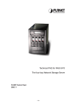
LYNX GigE Vision Software Manual
LYNX
GigE Vision
Software User’s Manual
These products are not intended for use in life support appliances, devices, or systems where
malfunction of these products can reasonably be expected to result in personal injury. Imperx
customers using or selling these products for use in such applications do so at their own risk
and agree to fully indemnify Imperx for any damages resulting from such improper use or
sale.
Copyright © 2007 Imperx Inc. All rights reserved. All information provided in this manual is
believed to be accurate and reliable. Imperx assumes no responsibility for its use. Imperx
reserves the right to make changes to this information without notice. Redistribution of this
manual in whole or in part, by any means, is prohibited without obtaining prior permission
from Imperx.
www.imperx.com
1 of 57
Rev 1.0 6/21/2007
LYNX GigE Vision Software Manual
Revision History
1.0
05/21/07 J. Egri
www.imperx.com
Initial Release
2 of 57
Rev 1.0 6/21/2007
LYNX GigE Vision Software Manual
Table of Contents
1.0
1.1
1.2
2.0
Introduction ........................................................................................ 7
The Scope of this Software User’s Manual................................................................ 7
Related LYNX User’s Manuals ................................................................................. 7
Overview of LYNX GEV ................................................................... 8
2.1
Application Highlights ............................................................................................... 8
2.1.1 Functional Description ........................................................................................... 8
2.1.2 Features .................................................................................................................. 8
2.1.3 Programmability..................................................................................................... 8
2.1.4 Applications ........................................................................................................... 8
2.2
Network Compatibility .............................................................................................. 9
2.2.1 LYNX eBUS Optimal Driver Mode ...................................................................... 9
2.2.2 LYNX eBUS Universal Driver Mode.................................................................. 10
2.2.3 Standard Driver Mode.......................................................................................... 10
2.2.4 Driver Comparison............................................................................................... 10
2.3
Acquisition Features ................................................................................................ 11
2.4
Equipment Requirements ......................................................................................... 11
2.4.1 PC Requirements.................................................................................................. 11
2.4.2 Network Adapter Requirements........................................................................... 12
2.4.3 Ethernet Switch Requirements............................................................................. 12
2.4.4 Fiber-Optic Interface Requirements..................................................................... 13
2.4.5 Power Requirements ............................................................................................ 13
2.5
Installation Overview ............................................................................................... 14
2.6
Control Inputs/Outputs............................................................................................. 14
2.7
LED Status ............................................................................................................... 14
3.0
LYNX GEV Application .................................................................. 15
3.1
Common Controls .................................................................................................... 16
3.1.1 File Menu ............................................................................................................. 16
3.1.2 Camera Menu ....................................................................................................... 17
3.1.3 Tools Menu .......................................................................................................... 17
3.1.4 Help Menu............................................................................................................ 25
3.1.5 Common Buttons ................................................................................................. 25
3.2
Connection Tab ........................................................................................................ 26
3.2.1 IP Engine Settings ................................................................................................ 26
3.2.2 Set IP Engine IP Address dialog .......................................................................... 28
3.2.3 IP Engine Connection Options............................................................................. 29
www.imperx.com
3 of 57
Rev 1.0 6/21/2007
LYNX GigE Vision Software Manual
3.2.4 Application Control Mode ................................................................................... 32
3.2.5 Camera ................................................................................................................. 33
3.3
Acquisition Tab........................................................................................................ 35
3.3.1 Acquisition Control.............................................................................................. 35
3.3.2 Options ................................................................................................................. 36
3.3.3 Status .................................................................................................................... 36
3.4
Image Saving............................................................................................................ 37
3.4.1 Image sequence .................................................................................................... 37
3.4.2 File formats .......................................................................................................... 38
3.4.3 Controls................................................................................................................ 38
3.5
Triggering Tab ......................................................................................................... 39
3.5.1 CC Pulse Generator.............................................................................................. 41
3.5.2 Ext. Trigger Delay................................................................................................ 42
3.6
LYNX Configurator Tab.......................................................................................... 44
3.6.1 Area of Interest (AOI) Tab...................................................................................... 45
3.6.2 Video Amp Tab....................................................................................................... 46
3.6.3 Exposure Tab .......................................................................................................... 47
3.6.4 Strobe Tab ............................................................................................................... 48
3.6.5 Auto Iris Tab ........................................................................................................... 48
3.6.6 Pixel Format Tab..................................................................................................... 49
3.6.7 Temperature Tab ..................................................................................................... 49
3.6.8 Workspace Tab........................................................................................................ 50
3.6.9 Miscellaneous Tab .................................................................................................. 51
3.6.10 Display Indicators ................................................................................................. 52
3.7
Diagnostic tab .......................................................................................................... 53
3.7.1 Controls pane .......................................................................................................... 53
3.7.2 Statistics pane.......................................................................................................... 54
3.7.3 Errors pane .............................................................................................................. 54
4.0
5.0
Gen<i>Cam ....................................................................................... 55
Technical Support ............................................................................ 57
www.imperx.com
4 of 57
Rev 1.0 6/21/2007
LYNX GigE Vision Software Manual
List of Tables
Table 1: LYNX IP Device Driver Performance Comparison .................................................. 11
List of Figures
Figure 1: Common Control Interface of LYNX GEV Application Panels.............................. 16
Figure 2: Color Adjustments Dialog ........................................................................................ 18
Figure 3: Connection Options Dialog ...................................................................................... 19
Figure 4: Application Options Dialog...................................................................................... 21
Figure 5: Memory Options Dialog........................................................................................... 22
Figure 6: Buffer Options Dialog .............................................................................................. 23
Figure 7: Display Options Dialog ............................................................................................ 24
Figure 8: Connection Panel...................................................................................................... 26
Figure 9: IP Engine Selection Dialog ...................................................................................... 27
Figure 10: Set IP Engine IP Address Dialog............................................................................ 28
Figure 11: Connection Flags Panel .......................................................................................... 29
Figure 12: Multi-target Configuration Panel............................................................................ 30
Figure 13: Unicast illustration.................................................................................................. 30
Figure 14: Multicast illustration............................................................................................... 31
Figure 15: Multi- Unicast illustration ...................................................................................... 31
Figure 16: Network Stack Port Selection Panel....................................................................... 32
Figure 17: Select Camera Dialog ............................................................................................. 33
Figure 18: Gen<i>Cam XML Selection Dialog....................................................................... 34
Figure 19: Acquisition Panel.................................................................................................... 35
Figure 20: Image Saving Dialog .............................................................................................. 37
Figure 21: Triggering Panel ..................................................................................................... 39
Figure 22: CC Pulse Generator Panel ...................................................................................... 41
Figure 23: Ext. Trigger Delay Panel ........................................................................................ 42
Figure 24: LYNX Configurator Panel ..................................................................................... 44
Figure 25: Area of Interest Tab................................................................................................ 45
Figure 26: Video Amp Tab. ..................................................................................................... 46
Figure 27: Exposure Tab.......................................................................................................... 47
Figure 28: Strobe Tab .............................................................................................................. 48
Figure 29: Auto Iris Tab........................................................................................................... 48
www.imperx.com
5 of 57
Rev 1.0 6/21/2007
LYNX GigE Vision Software Manual
Figure 30: Pixel Format Tab .................................................................................................... 49
Figure 31: Temperature Tab..................................................................................................... 49
Figure 32: Workspace Tab ....................................................................................................... 50
Figure 33: Miscellaneous Tab.................................................................................................. 51
Figure 34: Diagnostics Tab ...................................................................................................... 53
Figure 35: GenICam Explorer Dialog...................................................................................... 55
www.imperx.com
6 of 57
Rev 1.0 6/21/2007
LYNX GigE Vision Software Manual
1.0 Introduction
1.1 The Scope of this Software User’s Manual
This manual describes how to access and use features shared by Imperx’s growing family of
LYNX GigE Vision ( hereafter referred to as GEV ) cameras.
1.2 Related LYNX User’s Manuals
In addition to the shared features described in this manual, each LYNX GEV camera has
unique features relating to the type of image data it supports. These unique features are
described in the Lynx Hardware User’s Manual.
Note also that each LYNX GEV camera is one element of the LYNX Connectivity Solution.
As such, the cameras are shipped with two PC software packages: the LYNX IP Device
Driver (either the LYNX eBUS Optimal Driver or the LYNX eBUS Universal Driver); and
the LYNX GEV Software Development Kit (SDK – available in C++ or Visual Basic). These
software packages each have their own documentation.
In addition, Imperx offers two products that enhance LYNX Connectivity Solutions: LYNX
Hydra™ PC-to-PC Communications Software, and the LYNX High Memory Manager. Both
have their own documentation.
In summary, LYNX GEV cameras are supported by seven separate pieces of documentation:
•
•
•
•
•
•
•
•
Lynx Hardware User’s Manual
LYNX GEV Software User’s Manual (this manual)
LYNX GEV Driver Manual
LYNX GEV Advanced Driver Configuration
Reference Manual, the LYNX C++ Software Development Kit
Reference Manual, the LYNX Visual Basic Software Development Kit
User’s Manual, LYNX High Memory Manager
Reference Manual, LYNX Hydra PC-to-PC Communications Software
www.imperx.com
7 of 57
Rev 1.0 6/21/2007
LYNX GigE Vision Software Manual
2.0 Overview of LYNX GEV
2.1 Application Highlights
2.1.1
Functional Description
LYNX GEV cameras are feature rich, high-speed, high-resolution cameras that translate
imagery data into IP packets for transport over long-distance, high-speed, industry-standard
Gigabit Ethernet (GigE) networks. Cameras can be remotely accessed and controlled using
commercial GigE equipment.
LYNX GEV cameras can be used in a range of network types, including traditional point-topoint links, dedicated high-performance “machine-vision networks,” or standard corporate
Ethernet LANs (local-area networks). Regardless of the network type, direct connections
between cameras and host PCs can span up to 100 meters. With low-cost GigE LAN switches
or fiber, the reach is much further.
2.1.2
•
•
•
•
Most flexible, high-performance GEV camera in its class
FPGA (field programmable gate array)-based IP Protocol Camera for converting video
data to IP packets (no software-based operating system)
On-board, Intel 82540 GigE networking chip
Fully compatible with industry-standard Ethernet LAN equipment, including GigE
and Fast Ethernet equipment.
2.1.3
•
•
•
•
Features
Programmability
Access to all camera commands via IP port
Remote control of cameras using a single PC
Comprehensive LYNX Software Development Kit (SDK) for integrating the LYNX
GEV camera into custom systems
Field upgradeable software, firmware and lookup tables through the IP link
2.1.4
Applications
LYNX GEV cameras are ideal for applications that need to transfer large amounts of video
data from a camera to a local PC or via a LAN to a remote PC. These include:
•
•
•
•
Factory automation
Industrial inspection;
Post and parcel sorting;
Web inspection;
www.imperx.com
8 of 57
Rev 1.0 6/21/2007
LYNX GigE Vision Software Manual
•
•
•
Medical imaging;
Intelligent traffic systems; and
Security/Surveillance.
2.2 Network Compatibility
LYNX GEV cameras are fully compatible with industry-standard Ethernet LAN equipment.
In point-to-point connections, the cameras allow cameras and host PCs to be separated by up
to 100 meters without any intervening hardware. In networked configurations, with GigE
switches between cameras and PCs, or with fiber, the reach is unlimited.
For maximum network performance, use a non-blocking GigE switch. For applications
requiring peak bandwidths of less than 100 Mb/s, switches with non-blocking, 100-Mb/s ports
can be used.
To ensure efficient, highly reliable transfers where data is never lost, LYNX GEV cameras
add a protocol layer on top of the standard UDP/IP (User Datagram Protocol/Internet
Protocol) communications protocol. This LYNX GEV Protocol Layer verifies the receipt by
cameras and PCs of all video and command packets.
To maximize bandwidth availability, packets do not return an acknowledge message to the
camera, but are monitored by the LYNX application library. If a packet is missing or corrupt,
the application library transparently requests the camera to resend it.
LYNX GEV cameras support the multicast, or simultaneous transfer, of image data to more
than one host PC. One of the host PCs is configured as the master; the others are slaves that
receive data as configured and triggered by the master. To support multicasting, Layer 3 or –
in some cases, Layer 2.5 – GEV switches are required between the LYNX and the host PC.
Lower-performing switches may translate the multicast request into a broadcast. In some
applications, broadcasts may be sufficient. See ‘Equipment Requirements’, section 2.4 of this
manual for more details about which equipment to use.
2.2.1
LYNX eBUS Optimal Driver Mode
In high-performance mode, LYNX GEV cameras work with the LYNX eBus Optimal Driver
to transfer data between cameras and PCs with very low, predictable latency at rates of up to 1
Gb/s (100 MB/s). The video data is streamed directly into PC memory using almost no PC
CPU resources. This leaves the CPU free to process applications.
To achieve this performance level, PCs must be equipped with a GigE network interface (also
referred to as a network adapter) based on Intel’s 82540 chip. Many motherboard
manufacturers are designing this chip directly into their board in “LAN on the motherboard
(LOM)” implementations. Alternately, an Intel 82540-based network adapter, also known as a
network interface card, can be slotted into a PC. For more information about the equipment
needed to achieve the highest performance level, refer to ‘Equipment Requirements’ section
2.4 of this document.
www.imperx.com
9 of 57
Rev 1.0 6/21/2007
LYNX GigE Vision Software Manual
Note: The LYNX eBUS Optimal Driver supports LOM implementations, but the PCI
identification number for these may be different. Contact Imperx to obtain a driver
installation file compatible with LOMs.
2.2.2
LYNX eBUS Universal Driver Mode
The LYNX eBUS Universal Driver mode is recommended for applications where flexibility
is more important than performance, but more performance is required than can be achieved
using only the Windows network stack.
Similar to the drivers used in standard mode, the LYNX eBUS Universal Driver interoperates
with any vendor’s Ethernet network adapter. The driver shipped with the adapter is still
employed, but it communicates with the Filter Driver, instead of with the Windows network
stack.
All packets related to imaging are processed with high efficiency by the LYNX eBUS
Universal Driver. Other packets are forwarded to the Windows stack. In this way, a single
network adapter can support both an imaging application and normal corporate LAN
functions, such as web browsing and email.
2.2.3
Standard Driver Mode
In standard mode, LYNX GEV cameras interoperate with any vendor’s Ethernet network
adapter. The driver shipped with the adapter transfers the data to the Windows network stack,
which handles IP communications tasks.
Standard mode is recommended for applications where flexibility is more important than
performance. The Windows network stack uses significant levels of CPU processing power to
transfer data to memory, which can result in lost packets, severely degrading performance.
Standard mode is thus suitable for applications that require bandwidths of only 100 Mb/s or
less. If this mode is used with bandwidths of 1 Gb/s, application performance will greatly
degrade when CPU usage hits 100%. Additionally, at high rates like these, insufficient CPU
resources may be available to process or even display images.
2.2.4
Driver Comparison
The performance metrics in Table 1 may help users determine which driver mode best suits
their application requirements. The measurements were taken using an Intel P4 2.8 GHzbased PC with hyperthreading, 512 MB of memory, and Windows XP.
Although CPU performance and data transfer rates vary with PC configuration, relative
performance is roughly equivalent, independent of the PC.
www.imperx.com
10 of 57
Rev 1.0 6/21/2007
LYNX GigE Vision Software Manual
LYNX eBUS Optimal
Driver
LYNX eBUS Universal
Driver
Native Windows
Stack
Maximum Throughput
108 MB/s
82 MB/s
68 MB/s
CPU Usage
< 1%
< 15%
50%
Table 1: LYNX IP Device Driver Performance Comparison
With the hyperthreading CPU used in these tests, the 50% CPU usage measured for the native
Windows stack indicates that one complete processing thread was employed to transfer the
data. This leaves only one thread available for processing applications. By contrast, with the
LYNX eBUS Optimal Driver and the LYNX eBUS Universal Driver, one complete thread
and most of the second thread are available for applications processing.
2.3 Acquisition Features
The LYNX GEV camera family includes a wide range of models, each with it’s own frame
resolution and frame rate characteristics.
For more details about acquisition features, refer to the Lynx Hardware User’s Manual.
2.4 Equipment Requirements
2.4.1
PC Requirements
To achieve the highest performance level, LYNX GEV cameras must be used with the LYNX
eBUS Optimal Driver and the driver must be loaded into a PC with the following minimum
characteristics:
•
•
•
•
•
•
Processor: AMD Athlon XP 2000+ or Intel P4 2.0 GHz;
Memory: 512 MB DDR-RAM PC2700;
Motherboard: Mid-end without embedded graphic card;
VGA card: Nvidia GForce 2 or better (ATI not recommended); 1 2
GigE network adapter (either PCI card or LOM): Intel PRO/1000 MT family; and
Operating system: Windows 2K, Windows XP Professional, or SuSe Linux Ver. 8.2.
For standard performance, any Fast Ethernet or a GigE network adapter and its manufacturersupplied driver, as well as any AGP video card, can be used. For higher, mid-range
performance, the manufacturer’s driver can be used in tandem with the LYNX eBUS
Universal Driver.
1
Avoid using onboard video cards as they may compete with other components for shared memory.
2
Some ATI video cards will use a high amount of the PCI bandwidth and compete with other components, such
as the GigE network card. This may lower the expected data rate of applications.
www.imperx.com
11 of 57
Rev 1.0 6/21/2007
LYNX GigE Vision Software Manual
2.4.2
Network Adapter Requirements
The LYNX eBUS Optimal Driver works only with network adapters based on the Intel 82546,
82541, and 82540 network chips. The driver will also function with adapters based on the
Intel 82544 chip, but these are not recommended due to bugs in the chip that can cause
control packets to be lost if sent while data is streaming.
The PCI ID for some OEM network adapters may not be automatically recognized by the
LYNX eBUS Optimal Driver. If this occurs, contact Imperx to obtain an updated INF file.
The following four Intel network adapters are recommended:
1)
Intel®
Pro/1000
MT
Desktop
Adapter
(33-MHz,
32-bit
http://www.intel.com/network/connectivity/products/pro1000mt_desktop_adapter.htm
•
•
•
PCI):
Order Code: PWLA8391MT
(single packs)
Order Code: PWLA8391MTBLK (20 packs)
Order Code: PWLA8391MTLPBLK (low-profile 20 packs)
2) Intel PRO/1000 MT Server Adapter (up to 133-MHz, up to 64-bit PCI-X) Family:
http://www.intel.com/network/connectivity/products/server_adapters.htm
•
•
Order Code: PWLA8490MT
(single packs)
Order Code: PWLA8490MTBLK5 (five packs)
3) Intel® PRO/1000 MT Dual Port Server Adapter
•
•
Order Code:
Order Code:
PWLA8492MT
(Single Packs)
PWLA8492MTBLK5 (Five Packs)
4) Intel® PRO/1000 MT Quad Port Server Adapter
•
Order Code: PWLA8494MT
(Single Packs)
LAN on the motherboard (LOM) chips from Intel are also supported. Contact Imperx for
information on how to use these network chips with the LYNX eBUS Optimal Driver.
2.4.3
Ethernet Switch Requirements
Since LYNX GEV cameras comply with the Internet Protocol, the cameras should work with
all standard Ethernet switches. However, switches offer a range of functions and performance
grades, so care must be taken to choose the right switch for a particular application. The
following switches have been tested in-house for use with LYNX GEV cameras:
•
SMC (www.smc.com)
www.imperx.com
Tiger Switch 86xxT family
12 of 57
Rev 1.0 6/21/2007
LYNX GigE Vision Software Manual
Features: Layer 2 with IGMP v2.0 managed switch that supports jumbo frames and
multicast
•
3COM (www.3com.com)
3C1740x (3800 Family):
Features: Layer 2 with IGMP v2.0 managed switch that supports multicast
•
Dlink (www.dlink.com)
DGS-10xxTx 10/100/1000 family:
Features: Layer 2 unmanaged switch that converts multicast into a broadcast
The following switches are have been tested by others and are expected to work with LYNX
GEV cameras:
•
3COM (www.3com.com)
3C1770x (4900 Family):
Features: Layer 2 non-blocking switch that converts multicast into a broadcast
DGS-3308FG & DGS-3308-TG
• Dlink (www.dlink.com)
Features: Layer 3 non-blocking switch that supports multicast
• Cisco (www.cisco.com)
WS-C3750G-12S-S:
Features: Layer 3 switch that supports multicast
Note: Although these products are known to work with LYNX GEV cameras, their inclusion
in this manual does not guarantee they will meet specific application requirements.
2.4.4
Fiber-Optic Interface Requirements
In cases where no intervening switch is desired and camera-to-PC separations of more than
100 meters are required, a fiber-optic media converter can be used with LYNX GEV cameras.
The FlexPoint GX from Omnitron Systems (www.omnitron-systems.com) converts GigE to
fiber and vice versa. It supports multimode (MM) fiber over distances of up to 220 m (720 ft.)
and single-mode (SM) fiber up to 65 km (40 mi.) with SC, MT-RJ, or LC connector types.
Fiber-optic media converters from other manufacturers should also be compatible – even
those that convert Camera Link™ to fiber.
Note: Although these products are known to work with LYNX GEV cameras, their inclusion
in this manual does not guarantee they will meet specific application requirements.
2.4.5
Power Requirements
LYNX GEV cameras accept 4.5 V to 16 V power inputs using a 12-pin Hirose connector “HR
10A-10R-12P” (mating part “HR 10A-10P-12P”). Any DC power source providing sufficient
current drive should work. The following power supply is known to work:
12 V CUI Switching Supply: Model DSA-0151D-12.
Input:
100-240V
~47-63Hz
0.4A
Output:
+12V, 1.5A
Note: Although this product is known to work with LYNX GEV cameras, its inclusion in this
document does not guarantee it will meet specific application requirements.
www.imperx.com
13 of 57
Rev 1.0 6/21/2007
LYNX GigE Vision Software Manual
2.5 Installation Overview
The following steps should be taken to set up the camera:
1. Connect the network cable to the LYNX GEV camera
2. Connect power to the LYNX GEV camera.
You must also set up the other components of your system, including light sources, camera
mounts, heats sinks, host PCs, optics, and encoders.
For more details on the connectors required by different LYNX GEV camera models, refer to
the Lynx Hardware User’s Manual.
2.6 Control Inputs/Outputs
LYNX GEV cameras support the following I/O signals on the Hirose connector:
•
•
•
External Trigger input ( for synchronized frame acquisition )
Strobe output ( to control an external lighting source )
Auto Iris outputs ( for use with a motorized automatic iris lens )
All remaining control signals are provided through the LAN interface and can be accessed
through the camera library.
2.7 LED Status
The LYNX GEV camera provides three status LED indicators. One is on the rear-panel and
two are in the RJ-45 jack.
The LED on the rear-panel indicates the status of the camera. A steady green LED indicates
that the camera has powered up correctly and is active. A blinking LED indicates various
operating modes or error conditions. Please consult the Lynx Hardware User’s Manual for
more information.
The LED in the upper right-hand corner of the RJ-45 flashes when data is being transmitted or
received, and remains a steady green when the link is active.
The LED in the upper left-hand corner of the RJ-45 is green when an Ethernet connection is
established.
www.imperx.com
14 of 57
Rev 1.0 6/21/2007
LYNX GigE Vision Software Manual
3.0 LYNX GEV Application
The LYNX GEV Application is executable code based on the DLLs (dynamically linked
libraries) provided in the LYNX GigE Vision Software Development Kit (SDK). The
application offers users a fast, straightforward way to integrate any Imperx LYNX camera and
access camera features.
The LYNX GEV Application is a property sheet containing six main panels (or tabs):
•
Connection tab
•
Acquisition tab
•
Image Saving tab
•
Triggering tab
•
Lynx Configurator tab
•
Diagnostic tab
Throughout this section, the screen shots used to illustrate different panels highlight the
interface to the LYNX GEV cameras. For details on camera features, refer to the LYNX
Hardware User’s Manual.
Overview
Generally, you use the Lynx GEV application as follows:
1. Use the Connection tab to connect to your camera.
2. Use the Acquisition tab to display camera images on your PC.
3. Use the Image Saving tab to save images to disk..
4. Use the Triggering tab to configure hardware and software triggering options ( when
the control mode is set to Lynx Configurator ).
5. Use either the Gen<i>Cam node tree method or the Lynx Configurator method to
control the camera’s operating parameters.
6. Use the Diagnostic tab to find the cause of any acquisition problems you might have.
www.imperx.com
15 of 57
Rev 1.0 6/21/2007
LYNX GigE Vision Software Manual
3.1 Common Controls
All panels in the LYNX GEV Application have the same control interface. As shown in
Figure 1, the upper left-hand corner of each panel has menus for File, Camera, Tools and Help
and the lower right-hand corner has buttons for Gen<i>Cam, CamInfo and Help.
Figure 1: Common Control Interface of LYNX GEV Application Panels
3.1.1
File Menu
The file menu lets you create and save commands for XML configuration files for your Lynx
GEV camera. The menu contains the following items:
New: This command is used to clear configurations and cached file names from the
Connection tab (if any previous open or save has been performed).
Open…: This command is used to open a new XML configuration file. It displays the file
open dialog for selecting the file.
Save/Save As…: This command is used to save the current configuration to an XML
configuration file. If no file has been previously opened or saved, the file save dialog will
be displayed to select the location and name of the new file.
Save adapter as index: This option lets you create XML configurtion files for a large
number of identical PCs. Normally, Lynx GEV saves the XML configuration with the
MAC address of the NIC. However, even with an identical PC, the MAC address of the
NIC will always differ (because MAC addresses are always unique). Instead of using the
MAC address, Lynx GEV creates a list of all the NICs on the PC and identifies the NIC
by the position on the list (index). Lynx GEV produces the same list for an identical PC,
so the position on the list lets you reproducibly identify a NIC (even if the PC has several
NICs).
Ignore connectivity information: This option lets you save or load an XML
configuration file without the information required to connect to a specific camera. By
removing that specific information, you can use the XML configuration file for an
www.imperx.com
16 of 57
Rev 1.0 6/21/2007
LYNX GigE Vision Software Manual
identical NIC `and camera. You can find the omitted connectivity information in the IP
Engine settings pane, the Connection Options tab, and the Multi-target Configuration
dialog. In an XML file, you can identify the connectivity information by the
<connectivity> tag. (Though some information is reproduced inside the
<ip_engine> tag, it isn’t used for connectivity purposes.) When saving, the
connectivity information isn’t included; when loading, any connectivity information is
ignored.
Exit: This command is used to exit the application.
3.1.2
Camera Menu
This menu contains commands related to camera control. It contains the following item:
Reset Camera: This command is used to reset the camera.
Reset IP device: Reset the Lynx GEV IP engine.
Test connection: Test the current settings.
Reconnect: Reconnect to the currently selected camera.
Save device configuration to flash…: Opens the Save Device Configuration to Flash
dialog. When a camera supports this feature, this command saves the current
configuration to flash memory and makes it the default boot-up configuration.
3.1.3
Tools Menu
This menu contains the following items:
Color Adjustments: This command is used to invoke the color adjustments dialog, which
controls the gains to apply to the individual red, green, and blue channels of a color
camera. Note that this command is only available when the control mode is set to Lynx
Configurator.
The color adjustments dialog, as shown in Figure 2, is used to modify the color gains. It
can also analyze the color content of an acquired frame and propose red, green, and blue
gains.
www.imperx.com
17 of 57
Rev 1.0 6/21/2007
LYNX GigE Vision Software Manual
Figure 2: Color Adjustments Dialog
Run Information Gathering Tool: Run the Information Gathering Tool. This tool
gathers information about your system into a single text file. The tool gathers driver
information, network information, SDK versions information, available IP Engines, and
your XML configuration file. To use the Information Gathering Tool, see the Technical
Support section in the Lynx GEV Quick Start Guide.
Run Driver Statistics Tool: Run the Driver Statistics Tool. This tool can be used to
troubleshoot network problems when using the Lynx GEV High-Performance IP Device
Driver.
Run Driver Installation Tool: Run the eBUS Driver Installation Tool. This tool lets you
update and install all of Imperx’s Lynx GEV IP Device drivers, as well as the driver
supplied by Intel for the PRO/1000 Adapter. See the eBUS Quick Start Guide.
Set PLC Interrupt count to 0: Set the count value in PLC Interrupts in the Acquisition
tab to zero.
Options…: Open the Options dialog. This dialog let you control the settings and behavior
of the Lynx GEV application and provides the following tabs:
•
Connection Options
•
Application Options
•
Memory Options
•
Buffer Options
•
Display Options
www.imperx.com
18 of 57
Rev 1.0 6/21/2007
LYNX GigE Vision Software Manual
Connection Options tab
Figure 3: Connection Options Dialog
The Connection Options tab lets you configure how the camera connects with the PC, the
duration of timeouts, and so on.
‘Default Timeouts & Packet size’ panel
Answer Timeout: The maximum time, in milliseconds, the camera can take to respond to
a command from the application.
Request Timeout: The maximum time, in milliseconds, the host PC waits to receive all
the packets for a single image.
Packet Size: The maximum packet size, in bytes, that the camera can use to send image
data to the application. When connected point-to-point with the iPORT High-Performance
IP Device Driver, the maximum value is 8128 bytes. In networked applications, the value
depends on the maximum packet size that can be accepted by the switches between the
camera and the host PC. If the switches can be configured to support jumbo packets, you
can use the jumbo packet configuration to reduce packet overhead in the host PC. A
packet size of 1440 bytes should work with all networking equipment.
First Packet Timeout: The maximum time, in milliseconds, the camera can take to send
the first packet of image data to the application. When zero, the timeout is calculated
automatically from the request timeout.
www.imperx.com
19 of 57
Rev 1.0 6/21/2007
LYNX GigE Vision Software Manual
Packet Timeout: The maximum time, in milliseconds, the camrea can take to send
subsequent packets of image data to the application. When zero, the timeout is calculated
automatically from the request timeout.
Command Retry Count: The maximum number of times the Lynx GEV application
retransmits an unacknowledged command to the camera. When the application sends a
command to the camera, the camera transmits an acknowledge packet back to the PC
(application). If the application doesn’t receive the acknowledge packet within the time
specified by Packet Timeout, it retransmits the command. The retry count doesn’t include
the original command.
Automatic packet size detection: When enabled, the Lynx GEV application disregards
the Packet Size configuration and negotiates the optimal packet size with the IP Engine.
‘Default heartbeat settings’ panel
The heartbeat function lets the camera send data only when the host PC is properly
connected to the network. Using the heartbeat function keeps the camera from endlessly
transmitting data to a PC that has long since disconnected from the network (due to power
outage, network failure, etc.).
If the camera doesn’t receive a heartbeat signal before the configured maximum time, it
stops transmitting (as if it received a stop request). To restart transmission, the PC must
reconnect to the camera and explicitly start transmission.
Normally, the camera accepts heartbeat signals only from the PC to which it is connected.
However in Multicast mode, the camera accepts heartbeats from any PC because it can’t
tell which PCs are part of the multicasting group.Error! Bookmark not defined.
Heartbeat Expiration: The maximum time that the camera waits for a heartbeat signal
before stopping transmission. An expiration of 0 disables heartbeating.
Heartbeat Interval: The interval between the transmission of each heartbeat packet from
the PC to the camera. For proper operation, this value must be lower than the Heartbeat
Expiration.
www.imperx.com
20 of 57
Rev 1.0 6/21/2007
LYNX GigE Vision Software Manual
Application Options tab
Figure 4: Application Options Dialog
The Application Options tab lets you configure the flow of dialogs until you have
successfully connected to your camera.
Show device detection dialog on startup: Open the IP Engine Selection dialog upon
startup.
Show camera selection after detection: Automatically open the Select Camera dialog
after selecting a camera.
Do connection after camera selection: Automatically connect after choosing a camera.
Equivalent to clicking Connect.Error! Bookmark not defined.
Go to acquisition tab after connection: Cycle to the Acquisition tab after successfully
connecting to a camera.
Reuse last configuration on startup: Save the last used configuration to a temporary file
and reload it when starting the application.
Select GEV over iPORT when possible: If your camera supports the GigE Vision
protocol, this option lets you automatically use that protocol without changing settings in
the IP Engine Connection Options pane of the Connection tab.
www.imperx.com
21 of 57
Rev 1.0 6/21/2007
LYNX GigE Vision Software Manual
Memory Options tab
Figure 5: Memory Options Dialog
The Memory Options tab lets you configure how memory is allocated and used when
acquiring images.
Simple Memory Manager: When enabled, the application uses the simple memory
manager, which uses a pool of n buffers.
Max Buffer Count: The maximum number of buffers that the simple memory manager
will use.
High Memory Manager: When enabled, the application will get buffer memory from the
high memory manager instead of from normal user space memory. This option is
available only when the iPORT High-Memory Driver is in use.
First/Last Buffer ID: The ID of the first and last buffer that will be managed by the
iPORT High-Memory Driver. Coyote uses all the IDs from the first to the last, inclusively.
It is important that no two applications use IDs that overlap.
Release memory when application exits: When enabled, the iPORT High-Memory
Driver releases the buffers when Coyote closes (normally or not).
www.imperx.com
22 of 57
Rev 1.0 6/21/2007
LYNX GigE Vision Software Manual
Buffer Options tab
Figure 6: Buffer Options Dialog
The Buffer Options tab lets you configure how the buffer queue behaves when acquiring
images.
Buffer Queue Mode: Set the buffer queue mode. The queue mode indicates the behavior
of the buffer when the queue is full and new images are acquired. Available modes
include:
Remove first frame when full: When the buffer is full, discard the oldest images
to make room for new ones.
Drop new frames when full: When the buffer is full, discard new images.
Buffer Queue Size: The maximum size of the camera’s buffer queue, which is used to
store images for reading. When the buffer queue is full and a new image arrives from the
camera, the behavior of the buffer depends on the Buffer Queue Mode.
www.imperx.com
23 of 57
Rev 1.0 6/21/2007
LYNX GigE Vision Software Manual
Display Options tab
Figure 7: Display Options Dialog
The Display Options tab lets you configure how application displays the image window
when you begin acquiring images.
Display mode pane
Enable display: When enabled, each successful grab operation displays its image data in
a display window. If the window is closed, it will be opened on the first grab operation.
When disabled, grab operations are performed without displaying the image data.
Display fullscreen: When enabled, and the display window isn’t already opened, the
display window will be opened as full screen. Use the Escape key to get out of the full
screen mode. On a system with multiple monitors, you can select on which monitor the
full screen window appears.
Bayer Interpolation: When enabled, Bayer-to-RGB conversion will be performed.
Color mode: The color order for the display. Available options include:
Display adapter uses BGR: Application adjusts its output to use Blue, Green, and
Red ordering. Most adapters use this format.
Display adapter uses RGB: Application adjusts its output to use Red, Green, and
Blue ordering.
Display memory pane
Display memory type: The type of memory used by the display adapter. Available
options include:
www.imperx.com
24 of 57
Rev 1.0 6/21/2007
LYNX GigE Vision Software Manual
Use video memory: Display uses the video memory of the display adapter.
Use system memory: Display uses the system memory of the PC. Use this mode
if you encounter display problems when using the adapter’s video memory,
particularly when big images are being displayed on smaller display sizes (for
example, a 4K x 4K image is being displayed on a 1280 x 1024 display). Note that
this mode might impact CPU and resource usage.
3.1.4
Help Menu
The help menu contains the following item:
About…: This command will display the “About” box, which lists important information
about the version of the application and DLLs.
3.1.5
Common Buttons
Gen<i>Cam: This button opens the Gen<i>Cam node tree. Note that this button is only
available when the control mode is set to Gen<i>Cam.
CamInfo: This button displays manufacturing information read from the camera. Note
that this button is only available when the control mode is set to Lynx Configurator.
Help: This button displays the help file.
www.imperx.com
25 of 57
Rev 1.0 6/21/2007
LYNX GigE Vision Software Manual
3.2 Connection Tab
The Connection panel is used to edit the configuration of the GEV camera being used in the
application. As shown in Figure 8, the controls on this page display the configuration of the
currently selected camera.
Figure 8: Connection Panel
3.2.1
IP Engine Settings
IP address: The IP address of the currently selected camera. This field may be empty for
a point-to-point connection based on a Lynx GEV IP Device Driver.
Detect: Opens the IP Engine Selection dialog which searches the network for available
Lynx GEV cameras. When you select a camera, the information appears in the IP Engine
and NIC Information pane.
www.imperx.com
26 of 57
Rev 1.0 6/21/2007
LYNX GigE Vision Software Manual
Figure 9: IP Engine Selection Dialog
The IP Engine Selection dialog lets you locate cameras that are connected to a host
PC either directly or through a network switch.
The Available IP Engines pane displays the cameras that each NIC found.
The IP Engine and NIC Information pane provides detailed information about any
device you select in the Available IP Engines pane.
To select, click a camera in the Available IP Engines pane, then click OK.
Device name: The name of the currently selected camera.
Status: The connection state of the currently selected camera.
MAC address: The MAC address of the currently selected camera.
MAC address (NIC): The MAC address used by the network interface card (NIC).
Communication mode: Specifies which driver is used to make the connection to the
camera.
www.imperx.com
27 of 57
Rev 1.0 6/21/2007
LYNX GigE Vision Software Manual
3.2.2
Set IP Engine IP Address dialog
This dialog will appear after clicking on Detect, if the camera does not yet have an IP address
assigned. The Set IP Engine IP Address dialog lets you configure or change the IP address
of a camera. If there is a BOOTP or DHCP server on the network, the camera may already
have been given an IP address. It is your responsibility to ensure each camera has a unique IP
address.
Figure 10: Set IP Engine IP Address Dialog
IP Engine Settings
MAC address: The MAC address of the device. This address is unique and can be used
for camera identification.
IP address: The current IP address of the camera. It can be modified to change the IP
address of the camera.
Subnet mask: A mask used to determine which subnet the IP address belongs to. To
obtain the subnet address, the Lynx GEV application performs a bitwise AND operation
on the Subnet mask and the IP address.
www.imperx.com
28 of 57
Rev 1.0 6/21/2007
LYNX GigE Vision Software Manual
Gateway: The IP address of the device on the network that sends local traffic to other
networks.
3.2.3
IP Engine Connection Options
Connection Flags…: This dialog lets you configure how your camera acquires and maintains a
connection.
Figure 11: Connection Flags Panel
Setup device IP address at connect time: Force the specified IP address onto the
camera. When enabled and loading an XML file, the camera takes the IP address
specified in the XML file.
Internal automatic reconnection on connection lost: When enabled, the Lynx GEV
application program automatically attempts to reconnect if it loses its connection with
a camera. When disabled, the application reports a time-out and waits for the
connection to return. Disabling this flag may help with wireless networks, where
connectivity isn’t always stable.
Interrupt Port Keep Alive (useful when a firewall is present): When enabled, the
application sends regular dummy packets to the camera. The packets keep your
firewall from automatically closing an idle connection after it times out.
Multi-target…: This dialog lets you configure the camera to send images to multiple
PCs. You might use this option for machine vision applications where many PCs process
images from a single camera.
www.imperx.com
29 of 57
Rev 1.0 6/21/2007
LYNX GigE Vision Software Manual
Figure 12: Multi-target Configuration Panel
Multi-Target: The sending mode used when connecting to camera. Note that this list box
shows all the possible modes, since the Lynx GEV application program can’t determine
the modes that are supported by the camera until the connection is made.
Unicast: In unicast mode, the camera sends images to a single PC, on request. This
mode is the default data sending mode.
Figure 13: Unicast illustration
Multicast: In multicast mode, the camera sends each frame to a multicasting group, as
triggered by the master PC.
Multicasting uses the IGMP (Internet Group Management Protocol) and requires an
IGMP-compliant switch. The switch maintains a group list containing the group’s IP
address and the IP addresses of all the PCs that have subscribed to the group. The
multicasting group’s IP address is 224.64.16.xx; the xx part is configurable. When the
switch receives a packet addressed to the group, it sends individual packets to all the
(PCs) IP addresses in the list. Note that the Lynx Filter Driver doesn’t support
multicasting. To learn more about IGMPv3, see RFC 3376 at www.ietf.org.
www.imperx.com
30 of 57
Rev 1.0 6/21/2007
LYNX GigE Vision Software Manual
Figure 14: Multicast illustration
Multi-Unicast: This mode lets you send packets to multiple PCs without having an
IGMP-compliant switch. Where the switch maintained a group list in multicasting
mode, the camera maintains the list for multi-unicasting. The camera consecutively
sends each packet individually to each of the PCs, so a group of n PCs requires n times
the bandwidth compared to unicast.
Multi-unicast mode also lets you send a single image to a single PC, even if other PCs
are grabbing continuously.
Figure 15: Multi- Unicast illustration
Group address: The multicasting group IP address, used only in multicasting mode. The
usable IP addresses are restricted.Error! Bookmark not defined..
This application is the master: When enabled, the current PC will be the master client of
the camera. This applies to all modes, including unicast. When connecting a unicast client
as a slave, the Lynx GEV application program won’t be able to configure or trigger the
camera. This is useful when connecting to a camera that boots up in a streaming state.
Do not join group: Selects whether or not the multicasting master will join the group.
When the master doesn’t join the group, it won’t receive any image data from the camera.
www.imperx.com
31 of 57
Rev 1.0 6/21/2007
LYNX GigE Vision Software Manual
This mode is useful when a master PC controls several multicasting cameras, and the
combined bandwidth exceeds the capacity of the PC’s Ethernet link and/or PCI bus. The
master simply configures the cameras and then triggers them to stream their data.
Network Ports…: This dialog lets you configure the UDP ports.
Figure 16: Network Stack Port Selection Panel
When using the network stack to bring data into the PC, you can specify which UDP ports
will be used to connect to the camera. The default port value of 0 causes the network stack
to choose any available port. These values aren’t used when using the Lynx HighPerformance IP Device Driver or the Lynx Universal IP Filter Driver.
In some cases, you may want to force a port number to one or all of the three ports. For
example, you can save the camera’s configuration to flash while it is streaming. When the
camera boots up the next time, it starts sending frames right away. To ensure that the same
ports are used, specify each port rather than letting the camera choose available ports.
Command Port: The port over which commands from the host PC to the camera (and
acknowledgements from the camera) are sent.
Data Port: The port over which images are sent from the camera to the PC. For cameras
with multiple channels, channel #0 uses dataPort; channel #1, dataPort + 1.
Interrupts Port: The port over which the camera sends interrupts to the host PC.
3.2.4
Application Control Mode
Use Gen<i>Cam node tree: When enabled the camera uses the Gen<i>Cam standard to
communicate with the PC and opens the GenICam XML Selection dialog.
Use Lynx Configurator: When enabled the camera uses the Lynx Configurator graphical
user interface method to communicate with the PC.
www.imperx.com
32 of 57
Rev 1.0 6/21/2007
LYNX GigE Vision Software Manual
3.2.5
Camera
Camera type: The type of camera type currently attached.
Select: Opens the Select Camera dialog which lets you choose a camera configuration.
Note that this is only available when the control mode is set to Lynx Configurator.
Figure 17: Select Camera Dialog
Connect: Establishes a session with the currently detected camera. If the session is using
Gen<i>Cam as the control method then the GenICam XML Selection dialog will open.
The GenICam XML Selection dialog lets you select the source for the XML file that
describes how your camera works.
www.imperx.com
33 of 57
Rev 1.0 6/21/2007
LYNX GigE Vision Software Manual
Figure 18: Gen<i>Cam XML Selection Dialog
Download from first/second URL of device: Gen<i>Cam devices include up to two
onboard configurations in the form of an XML or a ZIP file. The URL includes the
file, the start address of the file, and the size of the file. The last two values are in
hexadecimal.
Retrieve from GenICam repository: The Gen<i>Cam repository is a location on
your hard drive. The path is %GENICAM_ROOT%/ vendorName/modelName.XML.
Select a file from the hard drive: Browse for your file on your hard drive.
Disconnect: Clear the configurations in the Camera settings pane and Camera pane.
www.imperx.com
34 of 57
Rev 1.0 6/21/2007
LYNX GigE Vision Software Manual
3.3 Acquisition Tab
The Acquisition panel, shown in Figure 19, is used to acquire images from the currently
selected and connected GEV camera.
Figure 19: Acquisition Panel
3.3.1
Acquisition Control
Mode: Specifies the acquisition mode. Can be one of the following:
Grab – Single: A single image will be acquired from the GEV camera.
Grab – Continuous: Images will be acquired continuously until the stop button is
clicked.
Recording: The camera will record, into it’s onboard memory, the next frames until either
the memory fills up or the Stop button is pushed. Images can be transmitted using the
“playback” acquisition modes.
www.imperx.com
35 of 57
Rev 1.0 6/21/2007
LYNX GigE Vision Software Manual
Playback – Single: A single image will be acquired from the frames in the camera’s
onboard memory. If no frames are available, a timeout will occur.
Playback – Continuous: Images will be acquired continuously from the camera’s
onboard memory. When no more frames are available, timeouts will occur.
Current channel: Select which channel the camera uses for the Acquisition tab. This field is
disabled if the camera supports only a single channel.
Number of frames: Specify the number of images to grab when using Grab – Single or
Playback – Single mode.
Start: This button is enabled only when no current acquisition is being performed. Clicking
on this button will start the acquisition of frames based on the acquisition mode.
Stop: This button is enabled when an acquisition is being performed. Clicking on it will stop
any current continuous acquisition.
3.3.2
Options
Keep partial images: Accept images that are missing pixels or lines. Use this option when
the image size is unknown or variable.
Don’t request lost packets: By default, missing packets are requested until they’re
successfully delivered. By enabling this option, lost packets are ignored and never
retransmitted. Images that are missing packets will appear incomplete.
3.3.3
Status
Display rate: The current rate of display in frames per second and the image ID for the last
displayed image. The rate is a cumulative value from the time the Start button was last
pressed, not an instantaneous rate. The image ID is assigned by the camera.
Acquisition rate: The current rate of acquisition of the camera, in frames per second. The
acquisition rate is a cumulative value from the time the Start button was last pressed.
Image count: The total number of images and the number of incomplete images. A large
number of incomplete images may indicate a set-up or cable problem.
Last error: The last error that occurred when acquiring images from the camera.
PLC interrupts: The Host PC Interrupt count; last input mask, and timestamp at the time the
camera generated the last interrupt.
www.imperx.com
36 of 57
Rev 1.0 6/21/2007
LYNX GigE Vision Software Manual
3.4 Image Saving
The Image Saving tab lets you save images in a variety of formats, including bitmapped
images and movies. If you save the images as a movie, you must specify the filename and
Codec (coder decoder). If you save the images individually, Lynx GEV automatically names
each file by individual frame ID; you need specify only the directory.
To save images, you must be currently acquiring images using the Acquisition tab. However,
you can configure the Image Saving tab and click Start, then configure the Acquisition tab.
The Lynx GEV application won’t save images until you click Start in the Acquisition tab.
Figure 20: Image Saving Dialog
3.4.1
Image sequence
Continuous: Save images indefinitely until you click Stop.
Fixed: Save a finite number of images.
Number of images: The number of Fixed images to save.
www.imperx.com
37 of 57
Rev 1.0 6/21/2007
LYNX GigE Vision Software Manual
3.4.2
File formats
TIFF: Allows users to save each acquired frame to a 16-bit TIFF file.
TIFF zero padding: Determines how to align 10/12 bit pixels into a 16 bit TIFF pixel.
Right (Normalized): 10/12 bits images will be saved to TIFF files with each pixel’s
LSBs padded with zeros.
Left (Non-normalized): 10/12 bits images will be saved to TIFF files with each
pixel’s MSBs padded with zeros.
Raw data files: Save each acquired frame into a raw, unformatted data file (.RAW). The
format depends on the grabber’s image and pixel settings output.
Windows BMP files: Allows users to save each acquired frame to a 24-bit RGB Windows
bitmap.
Movie: Allows users to save acquired frames to a single AVI movie file using the Codec you
specify.
Codec: The coder/decoder for the Movie.
File location or name: The directory for sequential images (files are named by image ID) or
the directory and filename for a text file or movie.
3.4.3
Controls
Start: Begin saving images.
Stop: Interrupt the process of saving images.
Progress: A bar that visually indicates the level of completion when saving a fixed number of
images. When continuously saving images, the bar isn’t used.
www.imperx.com
38 of 57
Rev 1.0 6/21/2007
LYNX GigE Vision Software Manual
3.5 Triggering Tab
The Triggering panel, shown in Figure 21, allows the user to configure the trigger settings of
the LYNX GEV camera when the Application Control Mode selection found in the
Connection dialog is set to Lynx Configurator. If the control mode is set to Gen<i>Cam then
this dialog is disabled.
Figure 21: Triggering Panel
Trigger: Selects the trigger source.
Off: When enabled, the camera is free running.
External: When enabled, the camera is set to triggering mode, and is expecting the trigger
signal from the external source (via the connector on the back).
CC: When enabled, the camera is set to triggering mode, and is expecting the trigger
signal from the CC Pulse Generator.
www.imperx.com
39 of 57
Rev 1.0 6/21/2007
LYNX GigE Vision Software Manual
Mode: Selects the trigger mode.
Standard: When enabled, the camera is set to standard triggering mode. The user can set
the number of frames captured via the “Captured Frames after Trigger” slider. The user
can also set the exposure time for the fist frame via the “First Frame Exp. – Standard”
slider.
Fast: When enabled, the camera is set to fast triggering mode. A frame is captured upon
receiving a trigger signal.
Double: When enabled, the camera is set to double triggering mode. Upon receiving a
trigger signal the camera captures two frames. The exposure for the first frame is user
programmable via the “First frame Exp. - Double” slider.
Exposure Control: Determines if the camera settings or trigger pulse width will determine
the exposure time.
Camera: When enabled, the user can set the exposure time for the first frame via the
“First Frame Exp. – Standard” slider.
Pulse Width: When enabled, the exposure for the first frame is determined by the pulse
width duration of the external trigger or CC pulse.
Ext. Trigger Edge: Specifies which edge of the external trigger signal will be used.
Rising Edge: Specifies that a rising edge should trigger the camera.
Falling Edge: Specifies that a falling edge should trigger the camera.
Ext. Trigger Delay: Specifies which external trigger delay mode should be used.
None: Indicates that there is no delay.
Programmable: Enables the “Ext. Trigger Programmable Delay” mode.
Encoder: Enables the “Ext. Trigger Encoder Delay” mode.
Captured Frames after Trigger: Specifies number of frames to be captured, when a trigger
event occurs. Minimum value is 1, maximum is 250 or continuous capture
First Frame Exp. - Standard: Specifies the exposure time in standard mode. Minimum value
is 10 microseconds, maximum is 655 milliseconds.
First Frame Exp. - Double: Specifies the exposure time in double mode. Minimum value is
1 microseconds, maximum is 65 milliseconds.
www.imperx.com
40 of 57
Rev 1.0 6/21/2007
LYNX GigE Vision Software Manual
3.5.1
CC Pulse Generator
Configures the operating parameters of the CC Pulse Generator.
Figure 22: CC Pulse Generator Panel
Granularity: Indicates the number of clock cycles that are used for each increment of the
width and the period. The amount specified in the granularity is multiplied by 30
nanoseconds (30 x 10-9 seconds). Minimum value is 1, maximum is 65535
Width: Specifies the amount of time (determined by the granularity) that the pulse
remains at a high level before falling to a low level. Minimum value is 1, maximum is
65535
Delay: Specifies the amount of time (determined by the granularity) that the pulse remains
at a low level before rising to a high level. Minimum value is 1, maximum is 65535
Period: Indicates the amount of time (also determined by the granularity) between
consecutive pulses.
Frequency: Indicates the frequency, in cycles per second, of the pulses.
Continuous: Causes the pulse generator to produce an unlimited number of pulses until
the Stop button is pressed.
Send only N Pulses: Causes the pulse generator to produce only N pulses, or until the
Stop button is pressed.
Start: Causes the pulse generator to begin producing pulses.
Stop: Causes the pulse generator to stop producing pulses.
Status: Indicates the current state, Stopped or Running, of the pulse generator.
www.imperx.com
41 of 57
Rev 1.0 6/21/2007
LYNX GigE Vision Software Manual
Important Note: Displays the following guidelines for configuring the CC Pulse
Generator:
When operating in the CC Trigger - Standard mode:
with Exposure Control set to 'Camera':
take caution to ensure that:
Period > ’First Frame Exp.-Standard’ + Readout_time
with Exposure Control set to 'Pulse Width':
take caution to ensure that:
Period > Width + Readout_time
When operating in the CC Trigger - Double mode:
take caution to ensure that:
Period > ‘First FrameExp.-Double’ + Readout_time
When operating in the CC Trigger - Fast mode:
take caution to ensure that:
Period > Readout_time
The camera's Readout_time is equal to 1/frame_rate. This time
varies depending on the camera's operating mode ( i.e. number
of taps, vertical window, etc. ). The current frame rate is
displayed in the Lynx Configurator dialog's 'Speed' indicator
box.
3.5.2
Ext. Trigger Delay
Configures the delay values when the Ext. Trigger Programmable or Ext. Trigger Encoder
delay modes are selected.
Figure 23: Ext. Trigger Delay Panel
www.imperx.com
42 of 57
Rev 1.0 6/21/2007
LYNX GigE Vision Software Manual
Ext. Trigger Programmable Delay: Specifies the delay between the trigger input signal
and the start of capture in microseconds.
Ext. Trigger Encoder Delay: Specifies the delay between the trigger input signal and the
start of capture in encoder's clock ticks.
www.imperx.com
43 of 57
Rev 1.0 6/21/2007
LYNX GigE Vision Software Manual
3.6 LYNX Configurator Tab
As stated earlier, there are two methods of controlling the operating parameters of a Lynx
GEV camera: LynxConfigurator and Gen<i>Cam. The choice of which method to use is
made in the Application Control Mode selection found in the Connection dialog. If the Lynx
Configurator control mode is chosen then the Lynx Configurator tab is available to be
selected.
The Lynx Configurator tab, shown in Figure 24, is a graphical user interface ( GUI )
containing several panels ( or tabs ) that are used to configure a LYNX GEV camera. Setting
parameters in this dialog causes configuration commands to be sent to the attached camera
and also controls the image display settings of the application.
Figure 24: LYNX Configurator Panel
www.imperx.com
44 of 57
Rev 1.0 6/21/2007
LYNX GigE Vision Software Manual
The LYNX Configurator is a graphical user interface (GUI) containing five main panels and
four common panels:
Main panels:
•
AOI (Area Of Interest)
•
Video Amp
•
Exposure
•
Strobe
•
Auto Iris
Common panels:
•
Pixel Format
•
Temperature
•
Workspace
•
Miscellaneous
This section gives a brief description of the different panels and highlights the main camera
configuration options. Please refer to the LYNX Hardware User’s Manual for a detailed
description of the camera features.
3.6.1 Area of Interest (AOI) Tab
The AOI tab is used to modify the active image area. As shown in Figure 25, there are
separate controls for horizontal and vertical windows.
Figure 25: Area of Interest Tab
www.imperx.com
45 of 57
Rev 1.0 6/21/2007
LYNX GigE Vision Software Manual
Horizontal AOI
Normal: When enabled, the imager has full horizontal resolution.
Window: When enabled, the user can set the horizontal resolution using the sliders or by
entering the desired start and end values.
Binning: When enabled, the image has half horizontal resolution.
Center: When enabled, the center (fast) mode is activated. This feature is only available
on the IPX-VGA210-V.
Vertical AOI
Normal: When enabled, the imager has full vertical resolution.
Window: When enabled, the user can set the vertical resolution using the sliders or by
entering the desired start and end values.
Binning: When enabled, the image has half vertical resolution.
3.6.2 Video Amp Tab
Using the Video Amp tab the user can control the gain and offset for each camera channel, as
shown in Figure 26.
Figure 26: Video Amp Tab.
Channel #1: The user can set the desired gain and offset for channel 1 via the sliders or by
entering the desired values.
Channel #2: The user can set the desired gain and offset for channel 2 via the sliders or by
entering the desired values.
Link Gain: When enabled, the gain sliders for both channels are linked together. If there is a
gain difference between the channels, this difference will be preserved.
www.imperx.com
46 of 57
Rev 1.0 6/21/2007
LYNX GigE Vision Software Manual
3.6.3 Exposure Tab
The Exposure tab, shown in Figure 27, controls the camera exposure.
Figure 27: Exposure Tab
Shutter Time: When enabled, the user can set the camera integration time via the slider or by
entering the desired value. This feature is used to shorten the camera integration.
Long Integration: When enabled, the user can set the camera to long integration mode. The
integration time can be programmed via the slider or by entering the desired value. This
feature is used to extend the camera integration.
Programmable Frame Rate/Time: When enabled, the user can set the camera frame rate or
frame time via the Frame Rate and Frame Time sliders or by entering the desired value. This
feature is used to reduce the camera speed while preserving the image resolution.
www.imperx.com
47 of 57
Rev 1.0 6/21/2007
LYNX GigE Vision Software Manual
3.6.4 Strobe Tab
The Strobe tab, shown in Figure 28, controls the strobe output position.
Figure 28: Strobe Tab
Strobe Position: When enabled, the user can set the strobe output position relative to the end
of the integration, via the slider or by entering the desired value.
3.6.5 Auto Iris Tab
The Auto Iris tab, shown in Figure 29, controls the auto iris feature.
Figure 29: Auto Iris Tab
Iris Threshold: When enabled, the user can set the iris threshold (brightness of the image) via
the slider or by entering the desired value.
www.imperx.com
48 of 57
Rev 1.0 6/21/2007
LYNX GigE Vision Software Manual
3.6.6 Pixel Format Tab
The Pixel Format tab, shown in Figure 30, controls the cameras pixel format.
Figure 30: Pixel Format Tab
Taps: Selects the camera output format.
Single: Sets the camera to the single tap mode.
Dual: Sets the camera to the dual tap mode.
Depth: Selects the output bit depth.
8 Bits: Sets the output to 8 bit.
10 Bits: Sets the output to 10 bit.
12 Bits: Sets the output to 12 bit.
Pixel Type: Selects the pixel type.
Grayscale: Causes pixels to be displayed in monochrome.
Bayer: Enables Bayer-to-RGB interpolation processing and color display.
Packed: Only available in 10 or 12 bit depth modes. Causes two 10 or 12 bit pixels to be
packed into 3 bytes as opposed to 4 bytes. Packing improves bandwidth efficiency.
3.6.7 Temperature Tab
The Temperature tab, shown in Figure 31, controls the temperature monitoring features of the
camera.
Figure 31: Temperature Tab
www.imperx.com
49 of 57
Rev 1.0 6/21/2007
LYNX GigE Vision Software Manual
Temperature Alarm: Controls the camera’s temperature monitoring function.
Enable: Turns on temperature alarm monitoring and reporting.
Set: Temperature at which the camera will generate an alarm set message.
Clear: Temperature at which the camera will generate an alarm cleared message.
Current Temperature: When the ‘Read’ button is clicked on, displays the current internal
temperature of the camera.
3.6.8 Workspace Tab
The Workspace tab, shown in Figure 32, controls the camera’s non-volatile configuration
memory.
Figure 32: Workspace Tab
Load from: Loads the camera registers from non-volatile memory.
Factory: Loads the camera registers and Lynx Configurator GUI with the original
(factory) settings.
User Space #1: Loads the camera registers and Lynx Configurator GUI with a saved
camera settings in the user space 1.
User Space #2: Loads the camera registers and Lynx Configurator GUI with a saved
camera settings in the user space 2.
Save to: Saves the camera registers to non-volatile memory.
User Space #1: Saves the current Lynx Configurator GUI settings to the camera User #1
space.
User Space #2: Saves the current Lynx Configurator GUI settings to the camera User #2
space.
www.imperx.com
50 of 57
Rev 1.0 6/21/2007
LYNX GigE Vision Software Manual
Boot from: Selects the ‘Boot From’ source. Upon power up, the camera will load its registers
from the selected ‘Boot From’ source.
Factory: The camera loads the original (factory) settings.
User Space #1: The camera loads the settings saved in User #1 space.
User Space #2: The camera loads the settings saved in User #2 space.
3.6.9 Miscellaneous Tab
The Miscellaneous tab, shown in Figure 33, controls miscellaneous camera features.
Figure 33: Miscellaneous Tab
LUT/FFC: Enables the use of the built in look-up or flat field correction tables.
Off: Disables the use of LUT and FFC.
LUT 1: Enables the use of lookup table #1.
LUT 2: Enables the use of lookup table #2.
FFC: Enables the use of flat field correction table.
FFC+LUT1: Enables the use of both the FFC and LUT #1 tables simultaneously.
( NOTE: This option is only available in the IPX-4M15-V , IPX-11M5-V and IPX-16M3-V
cameras ).
Test mode: Enables the test pattern generator.
Off: Turns off the test pattern generator.
Pattern #1: Selects the fixed test pattern 1.
Pattern #2: Selects the fixed test pattern 2.
Moving: Selects the moving test pattern.
Image Reversal: Enables the image reversal feature.
Negative Image: Enables the negative image feature.
www.imperx.com
51 of 57
Rev 1.0 6/21/2007
LYNX GigE Vision Software Manual
Noise Corr.: Enables the noise correction feature.
Defect Corr.: Enables the defective pixel correction feature.
Defect Map: Clicking on this button displays a listing of the contents of the Defective Pixel
Correction table stored in the camera’s non-volatile memory.
3.6.10 Display Indicators
All panels in the Lynx Configurator GUI display the following indicators:
Speed Window: Displays the current camera speed. Note that this is not active in trigger
mode.
Exposure Window: Displays the current camera exposure time. Note that this is not active in
trigger mode.
www.imperx.com
52 of 57
Rev 1.0 6/21/2007
LYNX GigE Vision Software Manual
3.7 Diagnostic tab
The Diagnostic tab provides basic information about the success of the image acquisition. It
can be used as a tool to gauge the performance of the GigE interface between the camera and
PC.
Figure 34: Diagnostics Tab
3.7.1 Controls pane
Start: Begin diagnosing the GigE connection.
Stop: Interrupt the diagnostic process.
Save…: Save the results as a text file.
www.imperx.com
53 of 57
Rev 1.0 6/21/2007
LYNX GigE Vision Software Manual
3.7.2 Statistics pane
The Statistics pane provides a running count of the images and image-related errors for both
valid and invalid images. Valid images may have errors if Keep partial images is
checked.Error! Bookmark not defined.
Count: The total number of images.
Frame overrun: The camera needs a few clock cycles to finish a frame. This error occurs
if a new frame starts before the camera has finished the previous frame.
Grabber FIFO overrun: The grabber ran out of RAM while acquiring an image. At least
one section of the image is missing.
Image dropped: The total number of images dropped by the IP engine. When a camera
transmits images faster than the IP Engine can relay them to the PC, the IP Engine drops
the image. The next image has an image-status bit set to indicate that the previous image
was dropped.
Partial line missing: The number of times a part of a line was missing in the IP Engine
(i.e. not sent by the camera). The value is incremented only once per image, even if all
lines in the image are partial.
Full line missing: A complete line is missing from a frame. This error may occur with
images of variable length.
Expected resend count: The number of packets (image pieces) that were re-requested
and received.
Ignored packet count: The number of packets received by the PC that were ignored due
to the lack of an available buffer. Packets unrelated to IP Engine data aren’t counted.
Lost packet count: The number of packets that were expected, but weren’t received
within a certain time limit or in the expected order.
Resent request count: The number of packets re-requested by the PC.
Start packet count: The number of packets the PC received (and ignored) while waiting
for the first image packet.
Unexpected resent count: The host PC re-requests packets that haven’t arrived within its
time limit. If both packets ultimately arrive, the second is counted as unexpected and
discarded.
3.7.3 Errors pane
Error Types: The total number of errors. Click Show to see a detailed list in the Error
Type dialog.
Missed Image Ids: The image ID of the last missed image. Click Show to see a full list in
the Missed Image dialog.
www.imperx.com
54 of 57
Rev 1.0 6/21/2007
LYNX GigE Vision Software Manual
4.0 Gen<i>Cam
As stated earlier, there are two methods of controlling the operating parameters of a Lynx
GEV camera: LynxConfigurator and Gen<i>Cam. The choice of which method to use is
made in the Application Control Mode selection found in the Connection dialog. If the
Gen<i>Cam control mode is chosen then a Gen<i>Cam button appears.
Clicking on the Gen<i>Cam button reveals the GenICam Explorer tab. The GenICam
Explorer lets you view and modify all camera features using the Gen<i>Cam protocol. It
displays the current values of all camera features as originally loaded from the Gen<i>Cam
XML file.
To learn more about the Gen<i>Cam standard and how the Gen<i>Cam XML file is
organized, visit www.GenICam.org.
Figure 35: GenICam Explorer Dialog
www.imperx.com
55 of 57
Rev 1.0 6/21/2007
LYNX GigE Vision Software Manual
GenICam node map: The Gen<i>Cam XML file is displayed as an expandable node tree.
This node tree is a listing of all supported features in the currently connected Lynx GEV
camera. The Node value pane and Node information pane show the detailed information for
a given selected feature.
Current visibility: Nodes have a visibility setting. Incremental settings allowed by the
Gen<i>Cam standard include Beginner, Expert, and Guru. A setting of Expert shows
Beginner and Expert nodes, but not Guru.
Node value: This pane typically shows the attributes for the selected feature. Attributes vary
depending on the selected feature. Typical attributes include value, range, increment,
minimum, maximum, etc. You can change the feature’s setting by entering a new Value and
clicking Apply.
Node information: This pane shows the Tool tip, Access, Visibility, and Caching values
associated with your selected feature.
www.imperx.com
56 of 57
Rev 1.0 6/21/2007
LYNX GigE Vision Software Manual
5.0 Technical Support
Additional technical support can be obtained by contacting Applications Support at Imperx,
Inc. at +1 (561) 989-0006 or via email at [email protected].
www.imperx.com
57 of 57
Rev 1.0 6/21/2007