1
PAD-250MAe-PN User Manual
automation technologies GmbH
PAD-250MAe-PN • User Manual
Restriction of warranty:
All information and advice in this manual are carefully checked and
correspond to the available data at press time. All data are for
information purposes only and no accuracy of statement is given.
Most of the mentioned labelings of soft- and hardware in this
document are registered trademarks and are liable to the legal
requirements.
Editor:
APEX automation technologies GmbH
Vossenkamp 4
38104 Braunschweig
Telefon 0531-3704-0
Telefax 0531-3704-299
http://www.apex.de
The controller PAD-250MAe-PN fulfills the demands of the
EU-directive 89/336/EWG „Elektromagnetische
Verträglichkeit“(electromagnetic compatibility). The conformity
of the controller PAD-250MAe-PN with the above mentioned
directive is confirmed by the CE-Sign.
2
Stand: 16.04.12
®
© 2012 by APEX automation technologies GmbH, Braunschweig
PAD-250MAe-PN • User Manual
TABLE OF CONTENTS
TABLE OF CONTENTS
TABLE OF CONTENTS.................................................................. 3
1
1.1
1.2
1.3
1.4
1.5
Preface ............................................................................. 5
Product Overview.............................................................. 6
Conventional Utilization .................................................... 6
General Advice ................................................................. 7
Scope of Delivery.............................................................. 8
Repair................................................................................ 8
2
2.1
2.1.1
2.1.2
2.1.3
2.1.4
2.1.5
2.2
2.2.1
2.2.2
2.2.3
2.2.4
Technical Data................................................................. 9
Interfaces ........................................................................ 10
PAB1-Bus ....................................................................... 10
PROFINET...................................................................... 11
USB................................................................................. 11
Serial Interface................................................................ 12
Operating Voltage ........................................................... 12
Software.......................................................................... 13
Conformance Class ........................................................ 13
Performance ................................................................... 13
Alarm Signals.................................................................. 13
Ressources ..................................................................... 13
3
3.1
3.1.1
3.1.2
3.1.2.1
3.1.2.2
3.1.2.3
3.1.2.4
3.1.3
3.1.4
3.2
3.2.1
3.2.2
3.2.2.1
3.2.2.2
3.2.3
Indicating and Operating Elements ............................ 14
Light-Emitting Diodes Groups......................................... 15
PROFINET-Status .......................................................... 16
Firmware-Status.............................................................. 17
FW: Boot-Phase .......................................................... 18
PROFINET-Connection-Establishment-Phase ........... 18
Setup-Phase................................................................ 18
Data-Transfer-Phase................................................... 19
Loader-Status ................................................................. 21
Rack-Status .................................................................... 21
Push-Button .................................................................... 22
Error confirmation ........................................................... 22
Loader ............................................................................. 22
Activate........................................................................ 23
Quit .............................................................................. 24
Restart............................................................................. 25
3
®
© 2012 by APEX automation technologies GmbH, Braunschweig
Stand: 16.04.12
PAD-250MAe-PN • User Manual
0 TABLE OF CONTENTS
1.1 Product Overview
3.2.4
Factory-Reset ................................................................. 26
4
4.1
4.2
4.3
4.4
4.5
4.6
4.7
4.8
4.9
Configuration and Operation....................................... 27
Hardware ........................................................................ 27
DIP-Switch ...................................................................... 27
GSD-File ......................................................................... 28
Device-Identification ....................................................... 29
PROFINET-Addressing .................................................. 29
Diagnostics-Module ........................................................ 30
Shutdown of outputs .. Fehler! Textmarke nicht definiert.
Undervoltage-Detection at restart................................... 32
Undervoltage-Detection during operation....................... 33
5
5.1
5.2
5.3
Update........................... Fehler! Textmarke nicht definiert.
Display of active firmware-version.................................. 34
Firmware Update ............................................................ 35
Display of active loader-version...................................... 35
6
6.1
6.2
6.2.1
6.2.2
6.3
6.4
Appendix ....................................................................... 36
Error Codes .................................................................... 36
Configuration with Step7 ................................................ 37
Installation of GSD-File................................................... 38
PROFINET-Adressing .................................................... 39
Display of HW- and FW-Version .................................... 40
Sequence Time.......... Fehler! Textmarke nicht definiert.
4
Stand: 16.04.12
®
© 2012 by APEX automation technologies GmbH, Braunschweig
PAD-250MAe-PN• User Manual
1
Preface
1 Preface
This manual shall assist you with the installation, the configuration
and the operation of PAD-250MAe-PN.
APEX automation technologies GmbH may do modifications of
specifications and further developments at any time without
notification.This may lead to deviations from this manual.
Hardware will be supplied by APEX automation technologies
GmbH together with a PDnetIP-CD, which contains software and
documentation necessary for the operation of PAD-250MAe-PN.
Please always use software and documentation of a PDnetIP-CD
as a unit.
The current PDnetIP-CD can be recalled under ftp2.apex.deT.
Please use for download user name kunde and for password
apex.
®
© 2012 by APEX automation technologies GmbH, Braunschweig
PAD-250MAe-PN • User Manual
1 Preface
1.1 Product Overview
1.1 Product Overview
PAD-250MAe-PN is a PROFINET IO-Device for connection of local
peripheral devices on basis of existing DTA-racks. Data transfer is
possible with every PROFINET IO-Controller.
1.2 Conventional Utilization
The PROFINET
determined to:
•
IO-Device
PAD-250MAe-PN
is
exclusively
connect a DTA 112 or DTA 113 with PROFINET IOController.
If PAD-250MAe-PN is used different as described in the manual,
no safe operation will be warranted.
The producer is not responsible for damages, additional
expenditures, problems, failures and especially not for all personaland property damages, which are resulting from unconventional
utilization.
For normal operation of PAD-250MAe-PN, following operational
restrictions are to be observed:
•
The serial interface will not be connected.
•
The USB interface will not be connected.
•
Cables for current supply must not exceed a length of
30 m.
•
PAD-250MAe-PN is not authorized for use in residential
area.
6
Stand: 16.04.12
®
© 2012 by APEX automation technologies GmbH, Braunschweig
PAD-250MAe-PN • User Manual
1 Preface
1.3 General Advice
1.3 General Advice
The installation of the PDnetIP-Controller should be accomplished
by qualified staff. APEX automation technologies GmbH does not
take responsibility for any damage due to improper installation.
This user manual explains installation and operation of PAD250MAe-PN. Information concerning control system respectively
programming system are to be taken from the corresponding
documentations.
PAD-250MAe-PN should remain in an antistatic-protective bag
until its installation.
If PAD-250MAe-PN is removed from the control application it will
have to be stored in an antistatic-protective bag.
7
®
© 2012 by APEX automation technologies GmbH, Braunschweig
Stand: 16.04.12
PAD-250MAe-PN • User Manual
1 Preface
1.4 Scope of Delivery
1.4 Scope of Delivery
Scope of delivery of PAD-250MAe-PN includes:
1. PAD-250MAe-PN in an antistatic-protective bag
2. CD-ROM PDnetIP incl.:
•
this manual
•
GSD-file
•
firmware
1.5 Repair
Please observe that, in case of repair, PAD-250MAe-PN will be
loaded with active firmware and other setup data within the
framework of checking.
Therefore it is important to possess all documentation and tools in
order to be able to re-establish the old configuration.
8
Stand: 16.04.12
®
© 2012 by APEX automation technologies GmbH, Braunschweig
PAD-250MAe-PN • User Manual
2 Technical Data
1.5 Repair
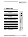
2 Technical Data
Allocation
Central-unit rack
DTA 112 (4 usable slots)
DTA 113 (9 usable slots)
Connection
PAB1-interface
Supply input
18 - 36 V / max. 4 A
Supply output
5 V / max. 9 A (at PAB1)
PROFINET-Connections
Quantity
2
Transmission rate
100 Mbit/Second
Ethernet 100Base-TX
Cable type
Twisted-Pair with RJ-45 connector Cat. 5
Serial interfaces
Quantity
2
Conduction physics
RS-232
Transmission rate
50 - 115.200 Bit/Seconds (usable baud rates are
different in protocols)
Connection
9 pole SubD-Socket
USB
Quantity
1
Conduction physics
USB 1.1
Transmission rate
Full speed (12 Mbps)
Connection
5 pole USB-Socket
Processor
Type
Fujitsu MB96F338USA with 32KB RAM + 544KB FLASH
Mechanical construction
Cardformat
Double europe card (234 mm x 160 mm)
Width
4 TE
Weight
500 g
Environmental conditions
Temperature
0 - 60 °C (in use), -40 - +85 °C (in storage)
Air humidityt
10 % - 80 % (non-condensing)
9
®
© 2012 by APEX automation technologies GmbH, Braunschweig
Stand: 16.04.12
PAD-250MAe-PN • User Manual
2 Technical Data
2.1 Interfaces
2.1 Interfaces
2.1.1
PAB1-Bus
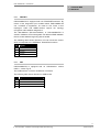
PAD-250MAe-PN exchanges data via PAB1-interface with E/A
cards in the rack and sends them to the PROFINET IO-controller.
Currently following E/A cards will be supported:
•
•
•
•
•
•
•
•
•
•
•
•
DAP 102
DAP 103
DAP 106
DAP 112
DAP 116
DAP 132
DEP 112
ADU 115
ADU 116
DAU 104
DAU 108
DAU 109
Maximum input and output data possible to transmit are 220 Byte.
Sequence time for actualization of input respectively output data
will be, if only digital cards are used, less than 4msec. In case of
using analog input cards, sequence time can be approximately
calculated as follows:
Sequence time < 4ms + 2ms x number of analog input cards.
A more detailed description concerning influence of analog cards
on data sequence time is to be found in attachment.
10
Stand: 16.04.12
®
© 2012 by APEX automation technologies GmbH, Braunschweig
PAD-250MAe-PN • User Manual
2 Technical Data
2.1 Interfaces
2.1.2
PROFINET
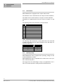
PAD-250MAe-PN is equipped with two PROFINET-interfaces. By
means of the integrated 2-port realtime-switch PAD-250MAe-PN
can, accordant to application, be used for star, linear or bus
topologies. LLDP and SNMP-routines support the topology
recognition and installation diagnostics.
The Mac-Address (Ethernet-Address) of PAD-250MAe-PN is
stored in hardware and unchangeable. All delivered PAD-250MAePN use a Mac-Address beginning with 00:05:DA.
The following table shows allocation of RJ-45 connection socket,
which corresponds to the IEEE802.3 Twisted Pair-interface.
Pin
Signal
1
Transmit +
2
Transmit -
3
Receive +
6
Receive -
2.1.3
USB
PAD-250MAe-PN is equipped with an USB-interface version
USB 1.1, socket Typ A.
The USB-interface is used for installation of firmware.
The following table shows allocation of USB-socket.
Pin
Signal
1
+5 V
2
Data -
3
Data +
4
GND
11
®
© 2012 by APEX automation technologies GmbH, Braunschweig
Stand: 16.04.12
PAD-250MAe-PN • User Manual
2 Technical Data
2.1 Interfaces
2.1.4
Serial Interface
PAD-250MAe-PN is equipped with a 9-pole SubD-socket.
The Firmware uses a serial interface for output of status indication.
The loader uses a serial interface for output of version indication.
Information on applied protocol can be found in chapter 5.1 and
5.3.
The following table shows allocation of serial interface.
Pin
RS-232, V.24 Signal
1
-
2
RxD
3
TxD
4
-
5
GND
6
-
7
-
8
-
9
Prg-Pin
- not allocated
The following table shows how a serial cable has to be converted
in order to be able to look at status indication on PC with help of a
terminal programme.
PAD-250MAe-PN
PC
2
3
3
2
5
5
2.1.5
Operating Voltage
PAD-250MAe-PN will be supplied with operating voltage via the
socket marked with „24 Volt“.
PAD-250MAe-PN may be operated with a feed-in from 18 V up to
36 V, fast fused by 6,3 A.
The trigger level for undervoltage survey is programmed to 20 V.
Thus, for normal operation, voltage should exceed this level.
12
Stand: 16.04.12
®
© 2012 by APEX automation technologies GmbH, Braunschweig
PAD-250MAe-PN • User Manual
2 Technical Data
2.2 Software
2.2 Software
2.2.1
Conformance Class
PAD-250MAe-PN corresponds to conformance class B and
supports the following RT-communication classes:
•
RT C1 (not-synchronized)
•
RT C2 (synchronized/not-synchronized)
2.2.2
Performance
PAD-250MAe-PN supports:
•
100 Mbps, full duplex
•
Sequence times of 1ms
•
Up to 220 Bytes cyclic- IO-data in each direction.
2.2.3
Alarm Signals
PAD-250MAe-PN supports:
•
2.2.4
Pull/Plug-alarm
Ressources
PAD-250MAe-PN supports:
•
9 Slots (a’ 1 Subslot) for alltogether 9 IO-cards in DTA-rack
•
1 Diagnostics-module
13
®
© 2012 by APEX automation technologies GmbH, Braunschweig
Stand: 16.04.12
PAD-250MAe-PN • User Manual
3
Indicating and
Elements
2.2 Software
Operating
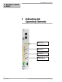
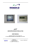
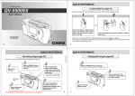
3 Indicating and
Operating Elements
LED P1..P4
PROFINET-Status
LED M1g/r..M9g/r
Rack-Status
Push-Button
LED F1..F8
Firmware-Status
14
Stand: 16.04.12
®
© 2012 by APEX automation technologies GmbH, Braunschweig
PAD-250MAe-PN • User Manual
3
Indicating and Operating
Elements
3.1 Light-Emitting Diodes
Groups
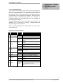
3.1 Light-Emitting Diodes Groups
For diagnostics without special tools PAD-250MAe-PN has 30
light-emitting diodes (LED) in order to represent the active
operating conditions. These LED’s are splitted into three groups:
•
PPOFINET-Status-LED group: is built up of the upper 4
LED’s, arranged in a square.
•
Rack-Status-LED group: is built up of 9 green and 9 red
LED’s, arranged in a double series.
•
Firmware-Status-LED group: is built up of 8 yellow LED’s
below the push-button.
The significance of PPOFINET-Status-LED group as well as RackStatus-LED group is dependent on condition of the FirmwareStatus-LED group. See chapter 3.1.2.
PROFINET-Status-LED group
Identifier
Inscription
Colour
Remark
P1
E.Lnk2
Green
Link Channel 2
P2
E.Lnk1
Green
Link Channel 1
P3
P.Sts
Green/Red
Status PROFINET IODevice Duo-LED
P4
P.Lnk
Green
PROFINET IO-Controller
Communication-Status
Colour
Remark
Double series 2 LED’s/Slot
Rack-Status-LED group
Identifier
Inscription
M1g/r
Slot1
Green/Red
M2g/r
Slot2
Green/Red
M3g/r
Slot3
Green/Red
M4g/r
Slot4
Green/Red
M5g/r
Slot5
Green/Red
M6g/r
Slot6
Green/Red
M7g/r
Slot7
Green/Red
M8g/r
Slot8
Green/Red
M9g/r
Slot9
Green/Red
15
®
© 2012 by APEX automation technologies GmbH, Braunschweig
Stand: 16.04.12
PAD-250MAe-PN • User Manual
3
Indicating and Operating
Elements
3.1 Light-Emitting Diodes
Groups
Firmware-Status-LED group
Identifier
Inscription
F1
PAD
F2
Hardware
F3
Setup
F4
PG
F5
Bus
F6
Serial
F7
Remote
F8
Rack
3.1.1
Colour
Remark
Loader/Firmware-display
Not supported
PROFINET-Status
The 3 green LED E.Lnk1, E.Lnk2 und P.Lnk, as well as the DuoLED P.Sts, conduce to the diagnostics of hardware-status of
PROFINET-interfaces. Control application of LED will be directly
carried out by hardware and is independent from firmware. LED’s
display active status of PROFINET-interfaces.
Display of PROFINET-Status-LED’s is only applied for in normal
operation when PAD-250MAe-PN has finished configurationphase. When this PAD is located in loader PROFINET-StatusLEDs give no information.
16
Stand: 16.04.12
®
© 2012 by APEX automation technologies GmbH, Braunschweig
PAD-250MAe-PN • User Manual
3
Indicating and Operating
Elements
3.1 Light-Emitting Diodes
Groups
Diagnostics PROFINET-Status
Identifier Contents
P1
P2
LINK
LINK
Status
Meaning
on
Port1 connection available
jittering
Port1 data transfer
off
Port1 no connection
on
Port2 connection available
jittering
Port2 data transfer
off
Port2 no connection
green on
PROFINET IO-Device initialized, no
error
green 1x
flashing
Diagnostics data
green 2x
flashing
Identification flashing (called up by
engineering-tool)
Configuration errror
- too many modules/submodules
P3
PROFINETSTATUS
red 1x
flashing
- too many IOs in IO-Controller
configuration
- IO-Controller-configuration does
not comply with existing
red 3x
flashing
No station name or IP-Address
red 4x
flashing
Internal error
off
Not initialized
Online, RUN
on
P4
PROFINETConnection
- Connection to IO-Controller OK
- IO-Controller in RUN-Status
Online, STOP
1x flashing
- Connection to IO-Controller OK
- IO-Controller in STOP-Status
off
3.1.2
Offline, no connection to IO-Controller
Firmware-Status
The Yellow LEDs conduce to diagnostics of firmware- or loaderstatus. When push-button is not actuated and the yellow PG-LED
(F4) is offline, firmware is running and the following description is
to be applied for. When PG-LED runs or flashes, PAD-250MAe-PN
is located in loader and description of chaper 3.1.3 is to be applied
for.
It can be distinguished between 4 phases when firmware is
running:
17
®
© 2012 by APEX automation technologies GmbH, Braunschweig
Stand: 16.04.12
PAD-250MAe-PN • User Manual
3
Indicating and Operating
Elements
3.1 Light-Emitting Diodes
Groups
3.1.2.1
FW: Boot-Phase
After power-up respectively reset all LEDs of rack-status-group and
firmware-status-group flash shortly. During boot-phase hardware
will be initialized and tested as well as active implementation of
DTA-rack will be find out. The yellow PAD-LED (F1) flashes.
After successful hardware-initialization the yellow PAD-LED (F1)
flashes constantly and PAD-250MAe-PN changes into
configuration-phase. This determined PAD-configuration will be
compared later with the one expected by the PROFINET IOController.
If an error is find out during the boot-phase, the yellow hardwareLED (F2) will start to flash and with help of the red rack-statusLEDs (M1r-M8r) an error code will be displayed (see chapter 6.1).
PAD-250MAe-PN rests in this state until next restart.
3.1.2.2
PROFINET-Connection-Establishment-Phase
After successful hardware-initialization PAD-250MAe-PN is in
PROFINET-Connection-Establishment-Phase and is waiting or
setup-data of PROFINET IO-Controller. This phase will be
displayed by flashing of the yellow Bus-LED (F5) and the remoteLED (F7). The PAD- LED (F1) is still running. The yellow Bus-LED
wil change to permanent online if another participant is found on
one of the two ethernet-channels.
After receipt of setup-data from PROFINET IO-Controller, the
yellow, constantly flashing, remote-LED (F7) displays the
established connection to PROFINET IO-Controller and PAD250MAe-PN changes into the setup-phase.
3.1.2.3
Setup-Phase
After successful communication-setup with PROFINET IOController, PAD-250MAe-PN is in setup-phase. In addition to the
PAD- LED (F1), the Bus-LED (F5) and Remote-LED (F7) are now
constantly running.
PAD-250MAe-PN compares the PAD-configuration expected by
the PROFINET IO-Controller with the determined PADconfiguration during the boot-phase. If all PADs expected by
PROFINET IO-Controller are available, the yellow Setup-LED (F3)
will be switched on constantly at the end of the setup-phase. The
yellow Setup-LED will flash if cards are missing or are plugged
incorrectly. Thereafter, PAD-250MAe-PN changes into the datatransfer-phase.
18
Stand: 16.04.12
®
© 2012 by APEX automation technologies GmbH, Braunschweig
PAD-250MAe-PN • User Manual
3
Indicating and Operating
Elements
3.1 Light-Emitting Diodes
Groups
3.1.2.4
Data-Transfer-Phase
After receipt and interpretation of setup-data by PROFINET IOController, PAD-250MAe-PN is in data-transfer-phase. PAD-LED
(F1), Bus-LED (F5)- und Remote-LED (F7) are flashing constantly.
Corresponding to the configuration comparison during the setupphase the yellow Setup-LED (F3) flashes or is switched on
constantly. Besides the yellow Rack-LED (F8) now displays the
state of PADs in DTA-rack.
A permanently flashing Rack-LED means that all PADs are
available and run error-free. In contrast a flashing Rack-LED
signals missing or defective PADs.
State of the single PADs will be displayed with the help of rackstatus-LED-group.
Diagnostics Firmware-Status
ID
Inscription
F1
PAD
F2
F3
F4
Hardware
Setup
PG
Status
Meaning
on
Normal state, HW-initialization completed
off
Boot-Phase, HW-Initialization + test wll be effected
off
Normal state, no error.
flashing
Firmware has discoverd a hardware error.
Rack-Status-LED-group displays error code (see
appendix)
off
Configuration data of PROFINET IO-Controller not yet
received.
flashing
Received configuration data do not comply with rack
interior.
on
Received configuration data comply with rack interior.
off
Normal operating state.
on
flashing
F5
Bus
F6
Serial
F7
F8
on
At least one ethernet connection available.
flashing
No Link at ethernet-port available.
off
Normal state, is currently not being supported
on
Communication with PROFINET IO-Controller runs
error-free.
flashing
No or defective communication with PROFINET IOController.
On
Normal state
flashing
Projected and found PAB1-card do not accord.
Or error-flag of PAB1-IO-card marked.
Or IO-outlets of a PAB1-card could not be set on proven
values.
Remote
Rack
Loader is running.
* Flashing of Setup-LED cannot be confirmed with the help of push-button.
19
®
© 2012 by APEX automation technologies GmbH, Braunschweig
Stand: 16.04.12
PAD-250MAe-PN • User Manual
3
Indicating and Operating
Elements
3.1 Light-Emitting Diodes
Groups
Causes for error messages
LED
Possible Cause
F2
Hardware
M1r..M8r-LED display error code (see appendix)
Task: Repair required.
F3
Setup
Will flash if configuration determined after power-up does not
comply with the one expected by PROFINET IO-Controller.
Task: Implement PADs according to expected configuration and
initialize restart.
F5
BUS
No link available at Ethernet-Port
Task: Check Ethernet-configuration
F7
Remote
No communication with PROFINET IO-Controller
Task: Check device name and IP-address.
F8
Rack
No or wrong PAD, Error-flag of PAB1-IO-card marked.
Task: Substitute defective IO-card .
20
Stand: 16.04.12
®
© 2012 by APEX automation technologies GmbH, Braunschweig
PAD-250MAe-PN • User Manual
3
Indicating and Operating
Elements
3.1 Light-Emitting Diodes
Groups
3.1.3
Loader-Status
Loader needs for status-display only the yellow PG-LED (F3). All
other LED are switched off when loader is active.
Diagnostics Loader-Status
ID
F4
3.1.4
Inscription
PG
Status
Meaning
off
Firmware runs and corresponding valid
table is to be found in chapter 3.1.2
on
Loader is in active state and new firmware
can be loaded via USB-interface.
flashing
Loader loads new firmware
Rack-Status
The state of a PAD found in a configured slot will be signalized by
the rack-status- LED’s M1r/g..M9r/g.
Diagnostics Rack-Status
Green Red
LED
LED
Meaning
on
off
Slot has been configured. Configured E/A-card is available
and operates error-free.
on
flashing
E/A-card signalizes an error. No data will be transferrred to
the PAD.
on
on
Meanwhile, E/A-card signalized an error that is no more
existent. Red LED can be confirmed by loader and
switches off thereafter.
off
flashing
No or wrong E/A card in slot.
off
off
Slot not configured.
*only valid, if PG-Status- and Hardware-LED are offline.
When PAD is defective the yellow rack-status-LED is also flashing.
If an hardware error of PAD-250MAe-PN is recognized during the
boot-phase of the firmware, the yellow hardware-LED and the
M1r..M8r-LED will display an error code (see appendix).
21
®
© 2012 by APEX automation technologies GmbH, Braunschweig
Stand: 16.04.12
PAD-250MAe-PN • User Manual
3
Indicating and
Elements
3.2 Push-Button
Operating
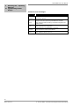
3.2 Push-Button
The push-button has different functions which are being activated
depending on activity time of push-button and active operation
type:
•
Confirm error Æ see chapter 3.2.1
•
Activate loader Æ see chapter 3.2.2.1
•
Quit loader Æ see chapter 3.2.2.2
•
Initiate restart Æ see chapter 3.2.3
•
Delete PROFINET-Address via Factory-Reset Æ see
chapter 3.2.4
3.2.1
Error confirmation
Pushing of push-button (at most 1 second) causes deletion of
internal error markers of firmware. Associated with this action the
yellow rack-LED (F8) changes from flashing to constant light and
the LED M1r..M8r switch off. Is the cause of error still existent, the
LED related to this error cause begins to flash again after some
time.
This flashing of the setup-LED (F3) cannot be resetted by pushing
of push-button. The yellow setup-LED will only flash constantly if
the PAD-configuration determined after a restart complies with the
one expected by the PROFINET IO-Controller.
A flashing hardware-LED can only be deleted by means of a
restart.
Bus-LED (F5) and remote-LED (F7) always display the active
status. Error markers will not be set. Flashing of this LED changes
to constant light when error cause is no more existent.
3.2.2
Loader
Depending on the aim to activate or quit the loader, it has to be
recognized before if loader or firmware is running. Differentiation is
possible with the help of PG-LED (F4). Firmware is running when
push-button is not being pushed and the PG-LED is offline. PAD250MAe-PN is in the loader when LED is running or flashing.
22
Stand: 16.04.12
®
© 2012 by APEX automation technologies GmbH, Braunschweig
PAD-250MAe-PN • User Manual
3
Indicating and
Elements
3.2 Push-Button
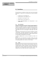
3.2.2.1
Operating
Activate
The following table shows how to activate the loader when
firmware is running. The image of the yellow LED F1 up to F8 is
marked in each column.
F1
F2
F3
F4
F5
F6
F7
F8
Column
1
2
3
4
5
6
z
{
z
{
z
{
z
z
{
{
{
{
{
{
{
{
z
{
{
{
{
{
{
{
z
z
z
z
z
z
z
z
{
{
{
{
{
{
{
{
{
{
{
z
{
{
{
{
Meaning
1
Firmware is running and no errors are existent.
2
Push-button has been pushed and all LED switch-off.
3
Every second further LED switch-off.
4
After 8 seconds all LED are.switched-on. If push-button is being
unhanded now, firmware will receive information to start loader.
5
All LED switch-off.
6
PAD-250MAe-PN initiates restart and is plugged in loader what is
recognizable by flashing PG-LED (F4).
23
®
© 2012 by APEX automation technologies GmbH, Braunschweig
Stand: 16.04.12
PAD-250MAe-PN • User Manual
3
Indicating and
Elements
3.2 Push-Button
Operating
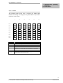
3.2.2.2
Quit
The following table shows how an activated loader can be quit
again. The image of the yellow LED F1 up to F8 is marked in each
column.
F1
F2
F3
F4
F5
F6
F7
F8
Column
1
2
3
4
5
6
{
{
{
z
{
{
{
{
z
{
{
{
{
{
{
{
{
z
{
{
{
{
{
{
{
{
{
{
{
{
{
z
{
{
{
{
{
{
{
{
z
{
z
{
z
{
z
z
Meaning
1
Loader is running.
2
Push-button has been pushed and LED F1 up to F8 switch-off.
3
In about a second timing the LED light walks down.
4
All yellow LED F1 up to F8 walked through.
5
When the last yellow LED F8 switches-off, PAD-250MAe-PN
initiates a restart. In this moment the push-button has to be
unhanded for firmware can start.
6
Firmware is running.
24
Stand: 16.04.12
®
© 2012 by APEX automation technologies GmbH, Braunschweig
PAD-250MAe-PN • User Manual
3
Indicating and
Elements
3.2 Push-Button
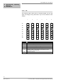
3.2.3
Operating
Restart
The following table shows how to initiate a restart. The image of
the yellow LED F1 up to F8 is marked in each column.
F1
F2
F3
F4
F5
F6
F7
F8
1
2
3
4
5
6
7
z
{
z
{
z
{
z
z
{
{
{
{
{
{
{
{
z
{
{
{
{
{
{
{
z
z
z
z
z
z
z
z
{
{
{
{
{
{
{
{
Å
{
Å
{
Å
{
Å
Å
{
{
{
{
{
{
{
{
Column
Meaning
1
Firmware is running and no errors are existent..
2
Push-button has been pushed and all LED switch-off.
3
Every second further LED switch-off.
4
After 8 seconds all LED are.switched-on.
5
After another second all LED switch-off. The push-button has to be
unhanded now, and firmware receives information to initiate a
restart.
6
Those LED, that flashed before pushing the push-button, flash one
time for a short moment.
7
All LED switch-off. Restart will be initiated
25
®
© 2012 by APEX automation technologies GmbH, Braunschweig
Stand: 16.04.12
PAD-250MAe-PN • User Manual
3
Indicating and
Elements
3.2 Push-Button
Operating
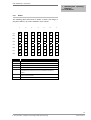
3.2.4
Factory-Reset
The Factory-Reset deletes the device unit name from the nonvolatile memory of PAD-250MAe-PN.
The following description is based on the state of PAD-250MAe-PN
without supply voltage.
F1
F2
F3
F4
F5
F6
F7
F8
Column
1
2
3
4
5
6
{
{
{
{
{
{
{
{
z
{
{
{
{
{
{
{
z
z
z
{
{
{
{
{
{
{
{
{
{
{
{
{
Å
Å
Å
Å
Å
Å
Å
Å
z
{
{
{
z
{
Å
{
Meaning
1
Push-button will be pushed, voltage returns and LED F1 up to F8
are switched-off.
2
The rack-LED switch-on, beginning with the PAD-LED (F1).
3
If the Setup-LED (F3) flashes, push-button will be unhanded. IPaddress and device name will be deleted.
4
The PAD effects a restart.
5
All Rack-LED flash for a short moment.
6
The rack-LED display the active operating state of PAD-250MAePN.
26
Stand: 16.04.12
®
© 2012 by APEX automation technologies GmbH, Braunschweig
PAD-250MAe-PN • User Manual
4
Configuration and
Operation
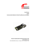
4.1 Hardware
4 Configuration and
Operation
4.1 Hardware
The PROFINET IO-Device PAD-250MAe-PN will be inserted into
the first slot of rack. When inserting into the rack the device unit
has to engage properly. After engaging of device unit safetyscrews have to be tightened. The device unit may only be inserted
if the state of the PAD is without supply voltage.
4.2 DIP-Switch
The 8-pole DIP-switch influences firmware in the following manner:
DIP-Switch
No
1
Status
Meaning
OFF
Expanded info-signals via serial interface
ON
Normal operation
2
3
Reserved
OFF
Data transfer only if expected rack configuration corresponds to
found rack configuration.
ON
Even though configured PADs are missing, data transfer will be
started with available PADs.
4..6
Reserved
7,8
DAP-Selection
Default-regulation of DIP-Switches: ON.
27
®
© 2012 by APEX automation technologies GmbH, Braunschweig
Stand: 16.04.12
PAD-250MAe-PN • User Manual
4
Configuration and
Operation
4.3 GSD-File
DIP-SW7/8 DAP-Selection
SW7
SW8
Meaning
OFF
ON
DAP-v2-RT
ON
OFF
DAP-v1-RT
OFF
OFF
ON
ON
DAP-Auto-Mode
In state of DAP-Auto-Mode PAD-250MAe-PN registers itself as
DAP-v2-RT device unit when first connection will be established.
Should be detected during first connection establishment that
PROFINET IO-Controller does not support the RT-C2communication-class, PAD-250MAe-PN reinitializes and registers
itself as DAP-v1-RT device unit (only RT-C1-communication).
4.3 GSD-File
The included GSD-File describes all modules supported by PAD250MAe-PN (see chapter 2.1.1), as well as the performance of
PAD-250MAe-PN in network.
The GSD-File will be integrated into the configuration tool of
PROFINET IO-Controller.
This file comprises 2 Device Access Points (DAP) for compatibility
with different interface characteristics respectively firmware
versions of the PROFINET IO-Controller:
•
DAP v1 RT
Corresponds to the GSDML-Specification 1.0 and is not
designed for PROFINET IO-Controller, which do not
support the interface- and port-concept of the GSDMLSpecifications 2.2. This DAP enables the RT-C1communication.
•
DAP v2 RT
Corresponds to the GSDML-Specification 2.2 and supports
its interface- and port-concept. This DAP enables the
synchronized and asynchronous RT-C2-communication.
Note: The communication-class will not be determined by means of
the application but only via the PROFINET IO-Controller during the
Network-Start-UP-Phase.
The name of the GSD-File is composed of the following
components:
GSDML-V2.2-APEX-PAD250MAe-PN-yyyymmtt.xml’
yyyy indicates the year, mm the month and tt the day of
generation.
28
Stand: 16.04.12
®
© 2012 by APEX automation technologies GmbH, Braunschweig
PAD-250MAe-PN • User Manual
4
Configuration and
Operation
4.4 Device-Identification
4.4 Device-Identification
PAD-250MAe-PN reports the following parameters in network:
Name
Value
Station Name
‘ ‘ will be generated during configuration
Station Type
PAD250PN
Manufacturer-ID
0x01B0 (440dez)
Device-ID
0x0010
MAC-Address
00:05:DA:xx:yy:xx
APEX automation technologies GmbH
4.5 PROFINET-Addressing
PAD-250MAe-PN will be addressed by PROFINET IO-Controller
via device name.
The assignment of device unit name will be done by the
configuration tool of the PROFINET IO-Controller. The IP-Address
will be assigned by PROFINET IO-Controller. The device name will
be backed-up non-volatile in PAD-250MAe-PN.
Delivery status of PAD-250MAe-PN is: No device name and no IPAddress (respectively 00:00:00:00:00:00). This status can be
restored by:
•
Factory-Reset with the push-button (see chapter 3.2.4).
•
Configuration tool (see chapter 6.2.2)
29
®
© 2012 by APEX automation technologies GmbH, Braunschweig
Stand: 16.04.12
PAD-250MAe-PN • User Manual
4
Configuration and
Operation
4.6 Diagnostics-Module
4.6 Diagnostics-Module
Status data of the respective PAB1-IO-cards will be gathered in the
diagnostics-module and broadcasted togehter with the cyclic IOdata.
Configuration Diagnostics-Module
Offset
Name
Meaning
0
DIAG_ERR_FLAGS
Error-bits of each single IO-card
2
DIAG_INFO
Reserved
4
DIAG_SLOT1
Status information Slot 1
6
DIAG_SLOT2
Status information Slot 2
….
….
….
20
DIAG_SLOT9
Status information Slot 9
Configuration DIAG_ERR_FLAGS-WORD
BIT-Offset
Meaning
0
Error-bit PAB1-IO-card Slot 1
1
Error-bit PAB1-IO-card Slot 2
….
....
8
Error-bit PAB1-IO-card Slot 9
9…13
Reserved (0)
14
Global error flag*
15
Reserved (always 1)
*The global error flag’ will be set, if an error bit of an IO-card is set or it is an existing
configuration mismatch in slot. The value for error-free status is 0x8000 in
DIAG_ERR_FLAGS.
30
Stand: 16.04.12
®
© 2012 by APEX automation technologies GmbH, Braunschweig
PAD-250MAe-PN • User Manual
4
Configuration and
Operation
4.6 Diagnostics-Module
Configuration DIAG_SLOTx-WORD
BIT-OFFSET Value
1
0
1
2
Meaning
Slot is configured
0
Slot is not configured
1
Wrong card in configured slot
0
-
1
No card in slot
0
-
3…14
Reserved (0)
15
1
Error-bit of PAB1-IO-card set
0
Error-bit of PAB1-IO-card deleted
Bit0..2 in DIAG_SLOT-WORD
B_2
B_1
B_0
Meaning
0
0
0
Not configured slot with card
1
0
0
Not configured slot without card
0
0
1
Configured slot with right IO-card
1
0
1
Configured slot without IO-card
0
1
1
Wrong card in configured slot
31
®
© 2012 by APEX automation technologies GmbH, Braunschweig
Stand: 16.04.12
PAD-250MAe-PN • User Manual
4
Configuration and
Operation
4.7 Shutdown of outputs
4.7 Shutdown of outputs
For device protection the outputs are shut down (all digital outputs
are set to ’0’, all analog output-register are set to 0x0000).
Following causes initiate shutdown of outputs:
•
PROFINET IO-Controller has entered ‚STOP’-state.
•
Connection to PROFINET IO-Controller is broken.
•
Undervoltage-detection is active.
After ‚Power-Up’ respectively ‚Reset’ of PAD-250MAe-PN all
found outputs are shut down until configuration data of
PROFINET IO-Controller are available.
4.8 Undervoltage-Detection at restart
After ‚Power-Up’ respectively reset and occured hardware
initialization the PAD-250MAe-PN checks input voltage as long as
valid voltage range has been reached (undervoltage-detection will
no longer be activated).
During this timing (a few ms) the yellow PAD-LED (F1) and yellow
Hardware-LED (F2) are flashing. The red rack-status LEDs
M1r...M8r are flashing and signalize the error-code 255
(undervoltage).
After input voltage has entered the valid voltage range the PAB1Bus will be scanned and found outputs will be shut down.
32
Stand: 16.04.12
®
© 2012 by APEX automation technologies GmbH, Braunschweig
PAD-250MAe-PN • User Manual
4
Configuration and
Operation
4.9 Undervoltage-Detection
during operation
4.9 Undervoltage-Detection during operation
If input voltage during operation drops in such a manner that
undervoltage-detection is activated automatically, first action will be
that all the outputs will be shut down for device protection.
Afterwards an undervoltage alarm signal will be sent to the
PROFINET IO-Controller. 1,5 seconds later PAD-250MAe-PN
initializes a restart.
Characteristics after restart are described in chapter 4.8.
33
®
© 2012 by APEX automation technologies GmbH, Braunschweig
Stand: 16.04.12
PAD-250MAe-PN • User Manual
5 Update
5.1 Display of active firmwareversion
5 Update
The PAD-250MAe-PN has to be in loader-mode for all
consecutively described updates . Chapter 3.2.2.1 describes how
to activate the loader in PAD-250MAe-PN.
Firmware as well as loader will be stored in separate ranges in the
CPU flashmemory of the PAD-250MAe-PN. The device name will
be stored in a separate flash memory.
Modifications of firmware or device name (eg. IP-Address) do not
influence the other ranges.
Setup-data will be broadcasted to PAD-250MAe-PNduring restart
of PROFINET IO-Controller.
5.1 Display of active firmware-version
Active firmware-version and HW-revision of the PAD-250MAe-PN
are stored in the I&M0-data. These values can be read by the
PROFINET IO-Controller and be displayed by a configuration tool.
See also chapter 6.3.
After Power-Up a version message will be registered via the serial
interface and can be recorded by the terminal programme.
Following interface parameter are to be used:
•
115.200 Baud
•
8 data bits
•
1 stop bit
•
no parity
34
Stand: 16.04.12
®
© 2012 by APEX automation technologies GmbH, Braunschweig
PAD-250MAe-PN • User Manual
5 Update
5.2 Firmware Update
5.2 Firmware Update
The firmware update will be done via the USB-interface with an
USB-Stick (FAT16/32) in whose main directory the firmware file
app.mhx has to be located.
For loading a new firmware, the following steps are essential:
•
Storing of the new firmware file in main directory of USBStick with file name „app.mhx“.
•
To bring PAD-250MAe-PN to enter the loader-status by
pushing of push-button (see chapter 3.2.2.1).
•
To connect the USB-Stick with the firmware-files.
•
After succesful download the PAD-250MAe-PN initializes a
reset and starts the new firmware.
5.3 Display of active loader-version
After activation of loader its version number will be registered via
the serial interface.
The loader activation is described in chapter 3.2.2.1.
The loader uses following protocol:
•
115.200 Baud
•
8 data bits
•
1 stop bit
•
no parity
35
®
© 2012 by APEX automation technologies GmbH, Braunschweig
Stand: 16.04.12
PAD-250MAe-PN • User Manual
6 Appendix
6.1 Error Codes
6 Appendix
6.1 Error Codes
If a hardware-error is find out during the boot-phase of firmware,
the yellow Hardware-LED (F2) will flash and the M1r..M8r-LED will
display an error-code.
Diagnostics Error-Code
Error-Code
Meaning
1
Error during I2C-Initialization
2..4
Eeprom-error
5
Error during PROFINET-Initialization
255
Powerfail.
The error-code is the sum of priority rating of the single rack-LED.
The priority rating of the LED is as follows:
LED
Priority rating
M1r
M2r
M3r
M4r
M5r
M6r
1
2
4
8
16
32
M7r M8r
64
128
36
Stand: 16.04.12
®
© 2012 by APEX automation technologies GmbH, Braunschweig
PAD-250MAe-PN • User Manual
6 Appendix
6.2 Configuration with Step7
6.2 Configuration with Step7
The description for configuration of PAD-250MAe-PN requires the
following preconditions:
•
The application of Step7, version V5.4 or higher.
•
A PROFINET IO-Controller with configured PROFINETSubnet.
The PAD-250MAe-PN will be integrated into the Step7 project in
the following manner:
•
The delivered GSD-file will be installed into the catalogue
of the HW-configuration.
•
PAD-250MAe-PN of the catalogue will be added to the
PROFINET- Subnet.
•
The rack of PAD-250MAe-PN will be provided with the
corresponding modules.
•
The device name of PAD-250MAe-PN will be assigned.
37
®
© 2012 by APEX automation technologies GmbH, Braunschweig
Stand: 16.04.12
PAD-250MAe-PN • User Manual
6 Appendix
6.2 Configuration with Step7
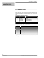
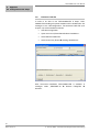
6.2.1
Installation of GSD-File
In order to be able to use PAD-250MAe-PN in Step7, PAD250MAe-PN including all optional modules will be installed into the
catalogue of the HW-configuration. The delivered GSD-File (see
chapter 4.3) will be installed as follows:
•
Start HW configuration.
•
Open menu item „Extras Î GSD-Datei installieren“ .
•
Select delivered GSD-File.
•
Select menu item „Extras Î Katalog aktualisieren“.
After successful installation PAD-250MAe-PN is available in
catalogue under „PROFINET IO Î Weitere Feldgeräte Î
General“.
38
Stand: 16.04.12
®
© 2012 by APEX automation technologies GmbH, Braunschweig
PAD-250MAe-PN • User Manual
6 Appendix
6.2 Configuration with Step7
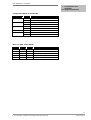
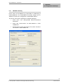
6.2.2
PROFINET-Addressing
Device name and IP-Address are responsible for addressing of
PAD-250MAe-PN. The PROFINET IO-Controller assigns the IPAddress on basis of the configuration of PROFINET-Subnet.
The device name will be assigned in the Simatic-Manager:
•
Select menu item „ZielsystemÎ Ethernet-Teilnehmer
bearbeiten“.
•
Select with „Durchsuchen“ the MAC-Address of PAD250MAe-PN.
•
Register device name and back-up with „Name zuweisen“
non-volatile in PAD-250MAe-PN.
39
®
© 2012 by APEX automation technologies GmbH, Braunschweig
Stand: 16.04.12
PAD-250MAe-PN • User Manual
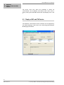
6 Appendix
6.3 Display of HW- and FWVersion
The above menu also offers the possibility to delete via
„Zurücksetzen“ the IP-Address and device name. After reset to
factory setting the PROFINET-Status LED (P3) displays error code
3.
6.3 Display of HW- and FW-Version
The hardware- and firmware-version numbers can be displayed by
the Simatic-Manager under menu item „HW Konfig Î Zielsystem
Î Baugruppenzustand“.
40
Stand: 16.04.12
®
© 2012 by APEX automation technologies GmbH, Braunschweig
PAD-250MAe-PN • User Manual
6 Appendix
6.4 Sequence Time
6.4 Sequence Time
The sequence time for update of input and output data depends on
implementation of the DTA-rack. The run-time for all global
routines without the data transfer time is about ~ 3ms. The data
transfer time to respectively of a digital IO-card is less than 0,1ms.
The data transfer time to an analog output card is also less than
0,1ms. The data transfer time for all data of an analog input card is
for example for the ADU 115 ~2ms (for the ADU 116 ~0,5ms). The
sequence time is the sum of all data transfer times of configured
cards and the 3ms run-time.
The data transfer time to an analog output card is the time needed
to write the output data into the D/A converter’s register. Until the
output data actually appear at the output another time interval
passes by which depends on the used converter on the analog IOcard. More detailed information to this topic are to be found in the
respective documents of the analog IO-card.
The data transfer time of an analog input card is the time needed
to make the measured values available in memory. The PAD250MAe-PN has no influence on the update time of measured
values in memory. This time will be determined only by the used
analog input card and is to be read in the documentation of the IOcard. The actual measure time for one channel can definitely be
about 20ms. Consequently, for 16 channels, an update time of
320ms can be expected.
41
®
© 2012 by APEX automation technologies GmbH, Braunschweig
Stand: 16.04.12