1
FreeWave Technologies
Multipoint Diagnostics Program
User Manual
Version 2.16D
LUM0003AB Rev C
1 of 63
FreeWave Technologies, Inc.
1880 South Flatiron Court
Boulder, CO 80301
(303) 444-3862
(303) 786-9948 Fax
www.freewave.com
FreeWave Technologies
900MHz, 2.4GHz, and 1.4GHz Spread Spectrum Modem
Multipoint Diagnostics Manual V 2.16D
Table of Contents
1
2
3
4
5
6
7
Introduction ............................................................................................................................................ 4
Hardware set-up...................................................................................................................................... 5
2.1
Diagnostics Computer .................................................................................................................... 5
2.2
Accessing the FreeWave Network.................................................................................................. 5
2.2.1
Direct access through the Diagnostics Port (FGR series Master) ........................................... 5
2.2.2
Direct access through an Ethernet network ............................................................................ 6
2.2.3
Indirect access through a Terminal Server.............................................................................. 7
2.3
Limitations...................................................................................................................................... 9
Radio set-up.......................................................................................................................................... 10
3.1
Set-up the Master.......................................................................................................................... 10
3.1.1
Invoke the Set-Up mode ....................................................................................................... 10
3.1.2
Ensure that the packet is big enough .................................................................................... 10
3.1.3
Set the Diagnostics rate ........................................................................................................ 11
3.1.4
Assign an IP address............................................................................................................. 12
3.2
Set up the other radios in the network .......................................................................................... 12
Communications set-up with the Master .............................................................................................. 13
4.1
Direct access through Serial Ports ................................................................................................ 13
4.2
Direct access through an Ethernet network .................................................................................. 15
4.3
Indirect access through a Terminal Server ................................................................................... 16
Managing the Network List.................................................................................................................. 19
5.1
Adding radios to the list................................................................................................................ 19
5.1.1
Adding a radio automatically................................................................................................ 19
5.1.2
Adding a radio manually ...................................................................................................... 19
5.1.3
Retrieving a Network List .................................................................................................... 20
5.2
Editing a radio's name................................................................................................................... 21
5.3
Deleting a radio ............................................................................................................................ 21
5.4
Saving the Network List ............................................................................................................... 22
Gathering and saving Data ................................................................................................................... 23
6.1
Polling method.............................................................................................................................. 23
6.1.1
Random Polling .................................................................................................................... 23
6.1.2
Sequential Polling................................................................................................................. 23
6.1.3
Manual Polling ..................................................................................................................... 23
6.2
Saving data ................................................................................................................................... 24
6.2.1
Generating a Diagnostics Log .............................................................................................. 24
6.2.2
Saving Radio Settings and plot data ..................................................................................... 25
Interpreting the Data............................................................................................................................. 27
7.1
Identifying Radios ........................................................................................................................ 27
7.2
Selecting display preferences ....................................................................................................... 28
7.2.1
Displaying Radio Serial Numbers or Names ........................................................................ 29
7.2.2
Selecting Signal Units........................................................................................................... 30
7.2.3
Selecting Imperial ("American") Or Metric Units ................................................................ 31
7.3
Reading Screen 0 .......................................................................................................................... 32
7.3.1
Network file.......................................................................................................................... 32
7.3.2
System Clock........................................................................................................................ 32
7.3.3
Master Radio line.................................................................................................................. 32
7.3.4
List of radios......................................................................................................................... 33
7.3.5
Scroll bars............................................................................................................................. 33
7.3.6
Radio's Serial Number or Name ("Radio")........................................................................... 34
7.3.7
Radio's function ("Fn") ......................................................................................................... 34
7.3.8
Radio link signal strength ("Sig")......................................................................................... 35
7.3.9
Radio link noise level ("Nse") .............................................................................................. 35
7.3.10 Receive success rate ("%") ................................................................................................... 36
7.3.11 Radio frequency error ("Freq ppm")..................................................................................... 36
7.3.12 Bytes transmitted ("DATA bytes")....................................................................................... 37
LUM0003AB Rev C
2 of 63
FreeWave Technologies
900MHz, 2.4GHz, and 1.4GHz Spread Spectrum Modem
Multipoint Diagnostics Manual V 2.16D
7.3.13 Length of radio link ("Dist")................................................................................................. 37
7.3.14 Total number of disconnects ("Num Dis") ........................................................................... 37
7.3.15 Repeater info ("Rep n" "N" "Sg")......................................................................................... 38
7.3.16 Diagnostics response rate ("Poll %").................................................................................... 42
7.3.17 Time of latest diagnostics response ("Time Rcvd").............................................................. 42
7.3.18 Number of Radios ("Number of Radios") ............................................................................ 43
7.3.19 Alarm Time .......................................................................................................................... 43
7.3.20 Poll Status Indicators ............................................................................................................ 43
7.4
Reading Screen 1 .......................................................................................................................... 44
7.4.1
Radio ID ("ID") .................................................................................................................... 44
7.4.2
Firmware Revision ("Rev") .................................................................................................. 44
7.4.3
Radio temperature ("Temp") ................................................................................................ 44
7.4.4
Supply voltage ("Vtg") ......................................................................................................... 45
7.4.5
State of RS232 port lines ("RTS", "CTS", "DTR") .............................................................. 45
7.4.6
Number of diagnostics requests received ("Polls Rcvd") ..................................................... 45
7.5
Reading Screen 2: "Remote Radio Setup Settings" ...................................................................... 46
7.5.1
Selecting a particular Radio.................................................................................................. 46
7.5.2
Settings' display .................................................................................................................... 47
7.6
Reading Screen 3, Signal Quality over Time................................................................................ 48
7.6.1
Selecting a particular Radio.................................................................................................. 48
7.6.2
Horizontal time scale ............................................................................................................ 49
7.6.3
Variables displayed............................................................................................................... 50
7.6.4
Vertical scale ........................................................................................................................ 50
7.7
Reading Screen 4: "Temp, Voltage, PPM Over Time"................................................................. 51
7.7.1
Variables displayed............................................................................................................... 52
7.7.2
Vertical scale ........................................................................................................................ 52
8 Editing the Radio's Settings.................................................................................................................. 53
8.1
Strategy......................................................................................................................................... 53
8.2
Changing a Radio's Settings ......................................................................................................... 55
8.3
Details about the Settings ............................................................................................................. 55
8.3.1
Risky changes ....................................................................................................................... 56
8.3.2
Xtal tune / SlicerThreshold / Frequency ............................................................................... 56
8.3.3
Settings that appear different from the Set-UP menu ........................................................... 57
9 Ending the session ................................................................................................................................ 61
10
Troubleshooting................................................................................................................................ 63
LUM0003AB Rev C
3 of 63
FreeWave Technologies
900MHz, 2.4GHz, and 1.4GHz Spread Spectrum Modem
Multipoint Diagnostics Manual V 2.16D
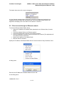
1
Introduction
2
The Diagnostics Program is used to monitor the performance of a
FreeWave Technologies Multipoint* network. Diagnostics helps to
identify actual or potential problems, quickly and conveniently, with
little or no interference to the normal operation of the network.
Diagnostics also makes it possible to remotely change almost any
setting of any modem.
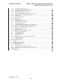
The Diagnostics System includes:
! A FreeWave Multipoint network
! A Computer running a Diagnostics Application
! A connection between the Diagnostics Computer and the Master radio.
* The Diagnostics System may be used in a Point-to-point network if the network is temporarily
reprogrammed as a Multipoint network.
LUM0003AB Rev C
4 of 63
FreeWave Technologies
3
900MHz, 2.4GHz, and 1.4GHz Spread Spectrum Modem
Multipoint Diagnostics Manual V 2.16D
Hardware set-up
To use Diagnostics, a diagnostics computer must be able to access the FreeWave network.
3.1
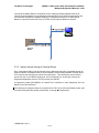
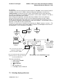
Diagnostics Computer
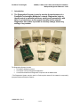
The Diagnostics Computer may be an additional computer; or it may be the computer already
connected to the FreeWave network's Master radio (as long as the computer has an extra RS232 port available, and it can run this application simultaneously).
Data Cable
Master
Polling Computer
Diag cable
Diagnostics Computer
The diagnostics computer's operating system must be Windows (’95, NT 4.0 or later).
Obtain the Diagnostics application from FreeWave Technologies (either on the User’s Manual CD
or by e-mail).
Create a new folder (such as “FreeWave Diagnostics”) on the Diagnostics Computer. Place the
Diagnostic application in this folder. The Diagnostic application will also store log and data files in
this folder. Creating a shortcut to the Diagnostic application on the desktop will make future use
easier.
3.2
Accessing the FreeWave Network
The Diagnostics Computer may access the FreeWave network Master radio in one of 3 ways:
! directly through the Diagnostics Port using RS232 (FGR, IM, and LRS series only)
! through an Ethernet network using UDP/IP (FGR and IM series Ethernet Radio only)
! through a Terminal Server and a network (LAN, Internet,…) using TCP/IP
3.2.1 Direct access through the Diagnostics Port (FGR, IM, and LRS series
Master)
If the network's Master radio is a series FGR, IM, or LRS radio, connect the diagnostics computer
to its Diagnostics Port.
Note: Do not confuse the Diagnostics Function with the Set-Up Mode. While the Set-up
Mode may use either the Diagnostics Port or the Data Port, the Diagnostics Function may
only use the Diagnostics port.
Two different Diagnostics cables are available, one for enclosed radios, and one for board level
radios. To acquire a diagnostics cable, contact FreeWave Technologies.
LUM0003AB Rev C
5 of 63
FreeWave Technologies
900MHz, 2.4GHz, and 1.4GHz Spread Spectrum Modem
Multipoint Diagnostics Manual V 2.16D
3.2.1.1 Diagnostics Cable for enclosed radio
For an enclosed FGR, IM, or LRS series, FGRM Series, and Ethernet board-level radios, the
diagnostics connection is through its dedicated Diagnostics port, using the diagnostics cable
ASC0409DC.
3.2.1.2 Diagnostics Cable for Board level radio
For full sized and non-Ethernet board-level FGR, IM, and LRS series Radios, the diagnostics
connection is through a black 20-pin port on the board using diagnostics cable ASC2009DC.
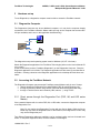
3.2.2 Direct access through an Ethernet network
The Diagnostics application can communicate directly with an Ethernet Master Radio through an
Ethernet network (such as a LAN) or even over the Internet. Both the Master Radio and the
Diagnostic computer must be connected to an Ethernet network, which typically is already the
LUM0003AB Rev C
6 of 63
FreeWave Technologies
900MHz, 2.4GHz, and 1.4GHz Spread Spectrum Modem
Multipoint Diagnostics Manual V 2.16D
case when the Master Radio is an Ethernet model. Assign the Ethernet Master Radio an IP
(Internet Protocol) address, just for diagnostic purposes (NOT the IP address of any device that
communicates through the FreeWave network). For Diagnostics directly to a FGR Ethernet
Master, the protocol used is UDP /IP (not TCP/IP), and no special cables are required.
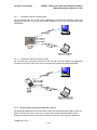
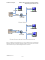
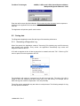
3.2.3 Indirect access through a Terminal Server
Even if the Master Radio is not an Ethernet model, diagnostics may still be accessed through an
Ethernet network. An additional device will be needed: a commercially available Terminal Server.
A Plus Series radio may also be used as a terminal server. Terminal Servers are an Internet
server with one or more RS232 serial ports, and one Ethernet port. In this type of setup, the
Diagnostics Application uses the TCP/IP protocol (not UDP/IP).
A Diagnostics Cable (ASC0409DC) is needed from FreeWave to send diagnostics from the
Master to the Terminal Server.
The following two examples show the connections for FGR, IM, or LRS series Master radios, and
for hosts connected either directly to the Master, or through the LAN/Internet.
LUM0003AB Rev C
7 of 63
FreeWave Technologies
900MHz, 2.4GHz, and 1.4GHz Spread Spectrum Modem
Multipoint Diagnostics Manual V 2.16D
LAN
FGR master, RS232 host
FGR master, Ethernet host. Note that 2 Terminal Server serial ports are used.
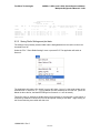
Enter the IP address of the Terminal Server in the "Chg IP Address" menu of the Diagnostics
Application. Afterwards, the Diagnostics Application will ask for a port number; enter the number
of the Terminal Server's port to which the Diagnostics cable is connected.
LUM0003AB Rev C
8 of 63
FreeWave Technologies
3.3
900MHz, 2.4GHz, and 1.4GHz Spread Spectrum Modem
Multipoint Diagnostics Manual V 2.16D
Limitations
Only radios with firmware at least level 2.29 (900 MHz), 1.58 (2.4 GHz) or 9.34 (1.4GHz) will
support diagnostics. (Certain features require even later firmware versions, as noted in this
manual).
While FreeWave radios will operate in the network regardless of the firmware revision level,
Diagnostics will be able to access, monitor and remotely set-up only radios with firmware that
supports diagnostics. Otherwise, the application will be limited to displaying the serial numbers of
such radios. Also, the application cannot access radios (even if they support diagnostics) through
repeaters with firmware that does not support diagnostics.
In the field, the firmware of any 2.4 GHz radio or any 900 MHz radio with serial number 571-0001
and higher can be upgraded. Older radios must be sent back to FreeWave for a hardware
upgrade. Contact FreeWave Technologies for more information.
While running diagnostics on a network has little or no effect on network operation, FreeWave
strongly recommends that the normal data flow is interrupted in a radio before using the
Diagnostics Application to change any of the radio's settings.
LUM0003AB Rev C
9 of 63
FreeWave Technologies
4
4.1
900MHz, 2.4GHz, and 1.4GHz Spread Spectrum Modem
Multipoint Diagnostics Manual V 2.16D
Radio set-up
Set-up the Master
To use diagnostics, the Master must be setup directly through its Set-up mode.
! Ensure that the packets have at least 32 bytes
! Turn on diagnostics and set a polling rate
! Assign an IP address to the radio (if using UDP/IP)
4.1.1 Invoke the Set-Up mode
Connect a terminal to the Master radio (see the Main Manual for more information on opening a
terminal window). Invoke the set-up mode (see the Main Manual for details on how to enter setup
with a particular radio).
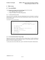
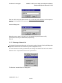
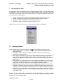
The terminal will show the Main Menu.
MAIN MENU
Version 2.47 5-24-2005
Standard Hop Table
Modem Serial Number 919-1968
(0)
(1)
(2)
(3)
(4)
(5)
(6)
(8)
(Esc)
Set Operation Mode
Set Baud Rate
Edit Call Book
Edit Radio Transmission Characteristics
Show Radio Statistics
Edit MultiPoint Parameters
TDMA Menu
Chg Password
Exit Setup
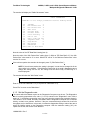
4.1.2 Ensure that the packet is big enough
Diagnostics require that the minimum packet size be at least 32 bytes. The radio calculates the
minimum packet size from the "Min Packet Size" and the "RF Data Rate" settings. (See the Main
Manual for information regarding packet sizes)
To check packet sizes from the Main Menu, press '3' ("Edit Radio Transmission Characteristics")
LUM0003AB Rev C
10 of 63
FreeWave Technologies
900MHz, 2.4GHz, and 1.4GHz Spread Spectrum Modem
Multipoint Diagnostics Manual V 2.16D
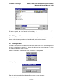
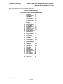
The terminal will display the "Radio Parameters" menu.
RADIO PARAMETERS
WARNING: Do not change parameters without reading manual
(0)
(1)
(2)
(3)
(4)
(5)
(6)
(7)
(8)
(9)
(A)
(B)
(C)
(Esc)
FreqKey
5
Max Packet Size 8
Min Packet Size 9
Xmit Rate
1
RF Data Rate
2
RF Xmit Power
9
Slave Security
0
RTS to CTS
0
Retry Time Out 255
Lowpower Mode
0
High Noise
0
MCU Speed
0
RemoteLED
0
Exit to Main Menu
Note the value of the "RF Data Rate" setting (item 4).
Note the value of the "Min Packet Size" setting (item 2). With an "RF Data Rate" of '2' the “Min
Packet Size" value must be '3' or more. With an RF rate of '3' the "Minimum Packet Size" value
must be '6' or more.
If the minimum packet size needs to be changed, press '2" ("Min Packet Size"),
NOTE: If the minimum packet size setting is changed, it must also be changed in all the
other radios in the network. If the Minimum Packet size is too small, diagnostics cannot
change the setting over the air; the change must be done locally via EZConfig or a
terminal program.
The terminal will show the "Min Packet" menu.
Enter Min Packet (0-9)
Enter '3' (if the "RF Data Rate" is '2') or '6'(if the "RF Data Rate" is '3').
Press "Esc" to return to the "Main Menu".
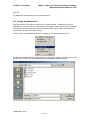
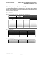
4.1.3 Set the Diagnostics rate
The rate at which the Master reports to the Diagnostics Computer must be set. The Diagnostics
rate is inversely proportional to the value ('1' to '63') entered in the "Diagnostics" menu. With a
setting of '1', the Master reports after every slot (every time the master hops to another channel).
This results in a lot of data. Normally, the Master and the Diagnostics Computer are connected
directly, so that's not a problem. However, if they are connected through another link, that link's
throughput may be insufficient. In that case, increase the diagnostics setting to reduce the rate at
which the Master reports to the Diagnostics computer. With the maximum setting ('63'), the
update rate is slow, but the link is not stressed.
LUM0003AB Rev C
11 of 63
FreeWave Technologies
900MHz, 2.4GHz, and 1.4GHz Spread Spectrum Modem
Multipoint Diagnostics Manual V 2.16D
The Diagnostics rate is set in the Master.
To do so, from the "Multi-Point Settings" Menu, press 'B' to select the “Diagnostics" menu.
Enter the Diagnostics Rate (0-63)
Code
0
1
2
n
63
Function
Diagnostics mode off
Diagnostics data sent every slot
Diagnostics data sent every other slot
Diagnostics data sent every nth slot
Diagnostics data sent every 63rd slot
The factory default is “0” (Diagnostics Off).
Press '1', or whatever rate is desired, then press Enter.
4.1.4 Assign an IP address
If the Diagnostics of an Ethernet Master Radio will be accessed directly through UDP/IP, a unique
IP address will need to be assigned to it.
NOTE: This IP address is only for diagnostics, and is unrelated to the IP address of any
device connected to the network.
From the Main Menu select "Set Operation Mode" ('0').
From the Operation Mode menu, select "Ethernet" ('F').
Form the Ethernet menu, select "IP Address" ('4').
Enter the IP address that will be used to access diagnostics.
Enter the address in the "Chg IP Address" menu of the Diagnostics application.
See the Ethernet addendum for more information.
4.2
Set up the other radios in the network
If the Master's "Min Packet Size" was changed, the setting must be changed in the other radios in
the network, through Set-Up mode (changing the min packet size requires a direct connection to
the radio: the setting can't be changed over the network from the Diagnostics Computer).
Instructions on invoking the Set-up mode and changing the "Min Packet Size" setting are in the
previous section.
LUM0003AB Rev C
12 of 63
FreeWave Technologies
5
900MHz, 2.4GHz, and 1.4GHz Spread Spectrum Modem
Multipoint Diagnostics Manual V 2.16D
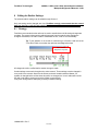
Communications set-up with the Master
In the Diagnostics computer, start the Diagnostics application. The program will open with
"Screen 0", with no diagnostics data and with the message “No Connection” (bottom left).
A connection between the Diagnostics Application and the Master radio must be established.
As mentioned, the Diagnostics Computer may access the Master radio in one of 3 ways:
! directly through Serial Ports using RS232
! directly through an Ethernet network using UDP/IP (Ethernet Master Radio only)
! indirectly through a Terminal Server and a network (LAN, Internet,…) using TCP/IP
5.1
Direct access through Serial Ports
To access the FreeWave network through a Serial Port (Data Port or Diagnostics Port):
! Connect the Master Radio to the Diagnostics computer using a Diagnostics cable;
! Select the Serial Port to which the Diagnostics cable is connected;
! Open that Serial Port.
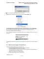
The Diagnostics Computer can use any of its Serial Ports (COM1 to COM8). The default is
COM1. Change the serial port via the "Communication" / "Chg Comm Port" menu.
LUM0003AB Rev C
13 of 63
FreeWave Technologies
900MHz, 2.4GHz, and 1.4GHz Spread Spectrum Modem
Multipoint Diagnostics Manual V 2.16D
A dialog opens. The currently selected port is highlighted.
Select the Serial Port, or press "Cancel" to retain the previous selection.
NOTE: If connected to a 1.4GHz network, the diagnostics baud rate must be changed to
57600. Both 900MHz and 2.4GHz use the 115200 baud rate.
Then, open the port with the "Communication" / "Open Comm" menu.
LUM0003AB Rev C
14 of 63
FreeWave Technologies
900MHz, 2.4GHz, and 1.4GHz Spread Spectrum Modem
Multipoint Diagnostics Manual V 2.16D
The bottom right corner of the screen changes to:
A Com1 Opened message doesn't necessarily mean that the Diagnostics Application has
established communications with the Master radio. When the program does connect, the
Application will display a list of the radios in the network in "Screen 0".
5.2
Direct access through an Ethernet network
To access an Ethernet Master Radio directly:
! Assign an IP address to the Master Radio (described in the "Software Set-up" section
above)
! Connect the Master Radio to the Ethernet network
! Connect the Diagnostics Computer to the Ethernet network
! Have the Diagnostics Computer create a connection to the Internet (The Application will
not create an Internet connection)
! Specify the IP address of the Master Radio
! Start the UDP/IP connection
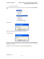
Specify the IP address of the Master Radio with the "Communications"/"Chg IP Address" menu.
A dialog opens.
Enter the new IP address of the Master Radio and click "OK".
A new dialog opens.
LUM0003AB Rev C
15 of 63
FreeWave Technologies
900MHz, 2.4GHz, and 1.4GHz Spread Spectrum Modem
Multipoint Diagnostics Manual V 2.16D
Click "OK" (the Master Radio doesn't use a Port Number).
Establish the IP connection with the "Communications"/"Connect UDP" menu.
The Application will try to establish the connection for approximately one minute. During that
time, the Application will stop responding to actions. If the IP connection is not established within
the time-out period, the Diagnostic Application will respond to commands and the “No
Connection” message remains on the screen.
If the connection is established, the Application displays the IP address in the lower left corner of
the screen.
The Application saves the IP settings when the Network file is saved (see "Saving the Network
List").
5.3
Indirect access through a Terminal Server
To access the Master Radio through a Terminal Server:
! Connect the Master Radio to a serial port on the Terminal Server.
! Connect the Diagnostics Computer to the Internet
! Have the Diagnostics Computer create a connection to the Internet (The Application will
not create an Internet connection by itself)
! Specify the IP address of the Terminal Server;
! Specify the port number of the Terminal Server;
LUM0003AB Rev C
16 of 63
FreeWave Technologies
!
900MHz, 2.4GHz, and 1.4GHz Spread Spectrum Modem
Multipoint Diagnostics Manual V 2.16D
Start the TCP/IP connection
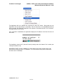
Specify the IP address of the Terminal Server with the "Communications"/"Chg IP Address"
menu.
A dialog opens.
Enter the new IP address of the Terminal Server and click "OK".
A new dialog opens.
Enter the port number of the Terminal Server to which the diagnostics cable is connected and
click "OK". (If a 'Y" diagnostics cable is used, use the port to which the end labeled "Diagnostics
Computer" is connected.)
Establish the IP connection with the "Communications"/"Connect TCPIP" menu.
LUM0003AB Rev C
17 of 63
FreeWave Technologies
900MHz, 2.4GHz, and 1.4GHz Spread Spectrum Modem
Multipoint Diagnostics Manual V 2.16D
The Application will try to establish the connection for about one minute. During that time, the
Application will stop responding to commands. If the IP connection is not established within the
time-out period, the Diagnostic Application will respond to commands and the “No Connection”
message remains on the screen.
If the connection is established, the Application displays the IP address in the lower left corner of
the screen.
The Application saves the IP (Internet Protocol) settings when the Network file is saved (see
"Saving the Network List").
IMPORTANT NOTE: If either a 900MHz or 2.4GHz radio is being used, the baud rate on the
terminal server should be set to 115,200kbps. If a 1.4GHz radio is being used, the baud rate
should be set to 57,600kbps.
LUM0003AB Rev C
18 of 63
FreeWave Technologies
900MHz, 2.4GHz, and 1.4GHz Spread Spectrum Modem
Multipoint Diagnostics Manual V 2.16D
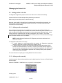
5 Managing the Network List
5.1
Adding radios to the list
The Diagnostics Application prepares a list of the radios in the network automatically.
A network list from a file that was previously saved may be retrieved.
Radios may also be added, edited or deleted manually.
Note that, once a radio is included in the list, and that radio is removed from the network, the
serial number will not be automatically removed from the list. The serial number should be
removed from the list manually.
5.1.1 Adding a radio automatically
Once the Diagnostics Application has established a connection with the Master Radio, the
software begins compiling a list of the radios in the network automatically. As the software finds a
radio, the radio will be added to the Network List, in the order that the radios were found. As the
software discovers a Repeater radio, the radio is assigned an "R #" number. The number
corresponds to the order in which the repeater functionality was found. The software also assigns
all of the radios a default name: "New Radio".
NOTE: A radio will not be listed as an “Rx” (Repeater) until a slave has been found
beyond the repeater.
The Application finds radios in two ways:
! If a radio happens to communicate within the network, the Diagnostics Application
notices the radio and the serial number will be added to the list
! If "Random polling" is selected, the Diagnostics Application generates random Serial
Numbers and asks the Master to call them. If a radio by that Serial Number happens to
be in the network, and responds to the call, the Diagnostics Application will add the serial
number to the list. The Diagnostics Application will eventually find any radio capable of
communicating with the Master.
For more information on polling see “Polling Method” later in this manual.
5.1.2 Adding a radio manually
A radio that wasn't discovered automatically may be added manually. However, its Serial Number
must be known.
Select the "EditRadio" / "AddRadio" menu, or press 'A' on the keyboard.
A dialog opens.
LUM0003AB Rev C
19 of 63
FreeWave Technologies
900MHz, 2.4GHz, and 1.4GHz Spread Spectrum Modem
Multipoint Diagnostics Manual V 2.16D
Enter the radio’s seven-digit Serial Number. Do not enter any other character (such as spaces or
hyphens) or the application will truncate the number.
Click OK.
A second dialog opens.
Optionally, enter a name for the radio, up to 8 characters long (any character is OK).
(This name is used for your identification purposes only)
Click OK.
5.1.3 Retrieving a Network List
If a Network List was previously saved, the list may be retrieved (instead of letting the Diagnostics
Application create the list from scratch every time the Application is run).
For more information on saving a network list, see “Saving The Network List” later in this manual.
Select the "File" / "Open Network File" menu or press alt-F-O.
The Windows' standard Open File dialog opens.
LUM0003AB Rev C
20 of 63
FreeWave Technologies
900MHz, 2.4GHz, and 1.4GHz Spread Spectrum Modem
Multipoint Diagnostics Manual V 2.16D
Find and select and open the Network List file desired, using standard Windows methods. (If the
file name is typed in, the ".rad" extension is not needed.)
5.2
Editing a radio's name
The only data about a radio that can be edited is its name. The radio's Serial Number must be
known. Follow the same procedure used to add a radio, and enter the new name.
5.3
Deleting a radio
If a radio is removed from the network, the Diagnostics Application will not automatically remove
the serial number from the Network List. Instead, the radio must be removed manually. To do so,
the radio's Serial Number must be known.
Select the "EditRadio" / "DeleteRadio" menu, or press 'D' on the keyboard.
A dialog will open.
Enter the radio’s seven-digit Serial Number. Do not enter any other character.
LUM0003AB Rev C
21 of 63
FreeWave Technologies
900MHz, 2.4GHz, and 1.4GHz Spread Spectrum Modem
Multipoint Diagnostics Manual V 2.16D
Click OK.
The Application removes that radio from the Network List.
5.4
Saving the Network List
Once the Network List of radios is complete, the list may be saved. The Network List will be
available the next time the same network needs to be analyzed. Saving the list has the advantage
of being faster and avoids having to manually enter the radios' names. Saving the Network List
also saves the IP (Internet Protocol) settings.
Select the "File" / "Save Network File" menu or pressing 'F' on the keyboard or alt-F-S.
The Windows' standard Save File dialog opens. Give the network a name so the list can be easily
accessed in the future. Save the Network List file using standard Windows methods.
LUM0003AB Rev C
22 of 63
FreeWave Technologies
6
900MHz, 2.4GHz, and 1.4GHz Spread Spectrum Modem
Multipoint Diagnostics Manual V 2.16D
Gathering and saving Data
The Diagnostics Application gathers data from the radios in the network through polling.
Specifically, the software gives the Master Radio the Serial Number of a radio to call. If the radio
with that Serial Number is accessible by the Master, the Application queries the radio about its
settings, performance and conditions.
6.1
Polling method
There are 3 polling methods: Random, Sequential and Manual.
Initially, the Application polls random Serial Numbers; random polling allows the Diagnostics
Application to eventually find any radio capable of communicating with the Master. Random
Polling is inefficient because there are 10,000,000 possible Serial Numbers, and the network has
relatively few radios. Once the Network List is complete, FreeWave recommends polling the
network through Sequential Polling.
In either case, a specific radio may be manually polled, if the Serial Number is known.
6.1.1 Random Polling
Select “Poll options” / “Poll in RANDOM mode”. Alternatively, press R while the Application is the
active window.
The application will poll all the possible Serial Numbers, randomly.
6.1.2 Sequential Polling
Select “Poll options” / “Poll in Sequential mode”. Alternatively, press S while the Application is the
active window.
The application will poll all the radios in the Network List, sequentially.
6.1.3
Manual Polling
Select the "EditRadio" / "PollRadio" menu or press 'P' on the keyboard.
A dialog opens:
LUM0003AB Rev C
23 of 63
FreeWave Technologies
900MHz, 2.4GHz, and 1.4GHz Spread Spectrum Modem
Multipoint Diagnostics Manual V 2.16D
Enter the radio’s seven-digit Serial Number. Do not enter any other character (such as spaces or
hyphens) or the application will truncate the number.
Click OK.
The Application will poll that specific serial number.
6.2
Saving data
The Diagnostics Application saves files with logs of the networks performance.
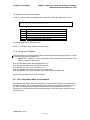
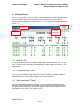
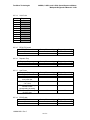
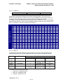
6.2.1 Generating a Diagnostics Log
When first opened, the Application creates a "Current.log" file (replacing any such file that may
have already been present). Every minute, the Application automatically logs events and
diagnostics data into this file.
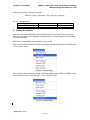
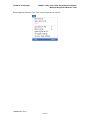
A file with a snapshot in time of that log may also be created: select the "File" / "Write Log File"
menu or press 'W' on the keyboard or alt-F-W.
The Application will create an "xxxxxxxxx.log" file with that snap shot. The name of the file is
based on when the snapshot was taken (month, day, hour, and minute). For example, the file
09072146.log was created on September 7 at 21:46 (9:46 PM).
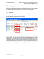
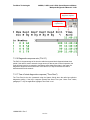
These files can be opened with any text editor or word processor. The following example of a log
file was opened in WordPad.
LUM0003AB Rev C
24 of 63
FreeWave Technologies
900MHz, 2.4GHz, and 1.4GHz Spread Spectrum Modem
Multipoint Diagnostics Manual V 2.16D
Diagnostics FGR Version 2.16
C:\Demo2.RAD
08-20-2005 12:44:35
424
Radio
Name
9191968
9191812
9191814
9192125
9192159
Fn
ID
M
SR1
Rep1
SR Slave
R1 Slave
R2
R1
S
S
9999
9999
9999
9999
Rev Temp VTG
C
V
47
29
13.6
47
47
47
47
29
30
27
30
13.8
13.7
13.1
13.3
RCD Sig Nse
%
Freq
ppm
44
LHL
LHL
LHL
LHL
89
95
98
85
57
31
71
62
Data
bytes
Dist Num Rep1 Rep2 Rep3 Rep4 Poll
Dis N Sg N Sg N Sg N Sg
%
0
99 -0.1
100 0.2
100 -1.1
92 0.2
0
0
0
0
Time
Rcvd
12:44:35
0.3
0.4
0.2
0.4
0
0
0
0
1
0
2
1
88
98
98 1 87
75
100
100
100
100
12:42:06
12:42:52
12:43:02
12:43:55
Number Radios=4
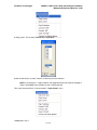
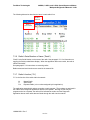
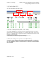
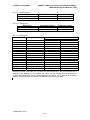
6.2.2 Saving Radio Settings and plot data
The settings of the presently selected radio and the data gathered from the radio over time can
be saved into a file.
Select the "File" / "Save Radio Settings" menu or press alt-F-R. The application will switch to
Screen 2.
The Application will create a file named "yyyyyyy.dat" where "yyyyyyy" is the serial number of the
selected radio. In Screen 0 or 1, yyyyyyy will be the radio at the top of the radio list. (Since the
Master is above the list, the Master's settings from Screen 0 or 1 can’t be saved.)
These files can’t be opened by double-clicking them because of the extension (".dat") which is
reserved by Windows. Instead, the file must be opened utilizing a text editor. Right clicking on
the file and selecting a text editor will also work.
LUM0003AB Rev C
25 of 63
FreeWave Technologies
900MHz, 2.4GHz, and 1.4GHz Spread Spectrum Modem
Multipoint Diagnostics Manual V 2.16D
Here is an example of such a file opened in Notepad.
Remote Radio Setup Settings
Radio Number 0 Serial 9065064 NAME:MASTER
0
Modem Mode
2
1
Baud Rate
48
2
Baud High Byte
0
3
RS232 Mode
16
4
MODBus RTU
255
5
Retry TimeOut
255
6
Xtal Tune
53
7
SlicerThreshold
144
8
Frequency
131
9
Freqkey
5
10 Max Packet Size
8
11 RF Data Rate
3
12 Min Packet Size
9
13 Xmit Power
255
14 RTS/CTS Control
0
15 Hop table size
112
16 Number Repeaters 1
17 Master Repeat
2
18 Max Slave Retry
9
19 Retry Odds
9
20 DTR Connect
0
21 Repeater Freq
0
22 LowPower
255
23 PPS Enable
255
24 Slave/Repeater
255
25 Master Sync
255
26 Network ID High
2
27 Network ID Low
232
28 SubNet ID
255
29 Radio ID High
255
30 Radio ID low
255
31 Freq Table
0
32 Diagnostics
0
33 Radio ID Super
255
34 Reflected Power 0
35 High Noise
255
36 Turn On Delay
255
37 Turn Off Delay
255
38
Xmit Power Cal. 168
39 Remote LED
0
40 Radio Name
1634
LUM0003AB Rev C
26 of 63
FreeWave Technologies
7
900MHz, 2.4GHz, and 1.4GHz Spread Spectrum Modem
Multipoint Diagnostics Manual V 2.16D
Interpreting the Data
The application uses five separate screens to display diagnostics data. These screens provide
comprehensive monitoring of all radio network settings including automatic logging of data from
each radio in the network. Screen 2 also allows changes to the operating settings of any radio in
the network from the Master radio.
!
!
!
!
"Screen 0" and "Screen 1" report the performance of all the radios in the network.
"Screen 2" display the settings of a given radio and allows changes to them.
"Graphics 3" plots the performance of a given radio over time
"Graphics 4" plots the conditions of a given radio over time
Select a Screen with the "Show” menu, or simply type its number on the keyboard.
7.1
Identifying Radios
In the following discussion there are as many as six ways of identifying a particular radio:
! Serial number (such as "123-4567"), a unique number permanently assigned to each
radio at the factory.
! Radio ID (such as "1234") which may be assigned to a radio, for convenience (not
necessarily a unique number).
! Name (such as "Repeater 2") which can be defined within the Diagnostics Application. In
newer firmware (2.64 for 900MHZ, 3.64 for 2.4GHz, and 8.34 for 1.4GHz), the radio
name can be assigned as an alpha-numeric value in the radio while being set up through
HyperTerminal.
! Radio Number (such as Radio # 0, which is the Master, and Radio #1, which is listed in
the top-most line in Screens '0' and '1'). The Diagnostics Application assigns this number
sequentially, as radios are discovered, and as radios are manually entered.
! Repeater Number (such as "R 3", which is the 3rd Repeater in Screens '0' and '1'). The
Diagnostics Application assigns this number sequentially, as radios are discovered to be
a Repeater. Note: a Repeater is not labeled as such until a Slave has reported through it.
! Repeater Order (such as "Rep1"; when the Diagnostics Application shows the record of a
given Slave, the Repeater Number of the Repeater directly linked to the Slave is placed
in the "Rep1" field).
Of these, only the Serial Number, the Radio ID, and the Radio Name are actually physically
located in the radio. All the other identifiers exist only within the Diagnostics Application, and are
exclusively for use of that application.
LUM0003AB Rev C
27 of 63
FreeWave Technologies
900MHz, 2.4GHz, and 1.4GHz Spread Spectrum Modem
Multipoint Diagnostics Manual V 2.16D
For example:
A radio to which the factory assigned the Serial Number of "123-4567", and into which a Radio ID
of "1234" is set by the user. In addition, within the Diagnostics Application, the radio name
"Hilltop Repeater" is entered by the user. (There is a 20-character limit on each radio name.)
The radio is programmed as a Repeater and placed in service within a Network. The radio is
directly linked to the Master and to a Slave.
Start the Diagnostics application, which first discovers the Master. Then 3 more radios are
discovered before serial number 123-4567 is found. Diagnostics assigns the radio a Radio
Number '4' and displays the serial number in the 4th line of the Radio List in Screens '0' and '1'.
The Diagnostics Application acknowledges the radio as a Repeater. The first radio is also a
Repeater, so radio S/N 123-4567 is labeled "R 2".
The path of a radio may be deciphered by examining the “Repx” columns in screen 1. The
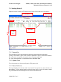
columns will always follow the same pattern: Rep1 is closest to the radio Rep2 is next and so on.
See paragraph 7.3.15 for information on Repeaters.
Repeater
R1
Slave
#2
Slave
#3
#1
Master
Diagnostics
computer
Serial Number 123-4567
Radio ID 1234
Repeater
#0
R2
#4
This is the 2nd repeater that the
Diagnostics Application
discovers and names it "R 2"
This is the 4th modem that the Diagnostics
Application discovers, placing it as the 4th
record in the Modem List
Selecting display preferences
LUM0003AB Rev C
28 of 63
#5
When looking at
this Slave's record,
the Repeater is in
column REP1
This modem can be identified six ways
This radio is identified as:
! Serial Number 123-4567
! Radio ID 1234
! “Hilltop Repeater”
! “R 2”
! #4 in the Radio List
! in the Rep1 column of Radio #5
7.2
In the Diagnostics
Application, this
modem has been
named "Hilltop
Repeater"
Slave
FreeWave Technologies
900MHz, 2.4GHz, and 1.4GHz Spread Spectrum Modem
Multipoint Diagnostics Manual V 2.16D
The Diagnostics Application offers a few choices for its displays.
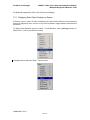
7.2.1 Displaying Radio Serial Numbers or Names
In Screens 0 and 1, there is a choice of displaying the radio’s Serial Numbers or the names that
have been assigned to them. Use the ‘N’ key on the keyboard to toggle between Serial Numbers
and names.
To display Serial Numbers, select the “Show” / “Serial Numbers” menu (warning: pressing ‘S’
doesn’t work: ‘S’ has a very different function)
To display names, select the “Show” / “Names” menu.
LUM0003AB Rev C
29 of 63
FreeWave Technologies
900MHz, 2.4GHz, and 1.4GHz Spread Spectrum Modem
Multipoint Diagnostics Manual V 2.16D
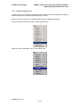
7.2.2 Selecting Signal Units
In Screens 0 and 1, the units for Signal Strength and Noise Level are either standard (just as they
would be displayed in the Radio’s Statistics Menu), or in dB!V.
Note that the units in Screen 3 are standard (dB!V cannot be displayed in that plot).
Select the “Show”/”RSSI regular” menu to select standard units.
Select the “Show”/”RSSI dB!V” menu to select dB!V units.
LUM0003AB Rev C
30 of 63
FreeWave Technologies
900MHz, 2.4GHz, and 1.4GHz Spread Spectrum Modem
Multipoint Diagnostics Manual V 2.16D
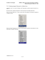
7.2.3 Selecting Imperial (“American”) or Metric Units
In Screens 0 and 1, the units for Distance and Temperature are either Imperial (“American”), or
metric.
Note that Screen 4 displays temperature in Celsius (that plot can’t display Fahrenheit).
Select the “Show”/”Metric km, C” menu to select metric units (distance in Kilometers, temperature
in degrees Celsius).
Select the “Show”/”American mi, F” menu to select Imperial (“American”) units (distance in miles,
temperature in degrees Fahrenheit).
LUM0003AB Rev C
31 of 63
FreeWave Technologies
7.3
900MHz, 2.4GHz, and 1.4GHz Spread Spectrum Modem
Multipoint Diagnostics Manual V 2.16D
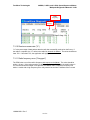
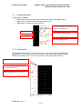
Reading Screen 0
Diagnostic Screen 0 reports the RF performance of each individual radio link in the network.
Network file
System clock
Master
List of
all other
radios
Scroll-up the
list of radios
Scroll-down the
list of radios
7.3.1 Network file
This is the name of the file (and its path) from which the present network info was taken.
Typically, each network is given a name. When the application is setup to monitor that network, a
file can be saved and typically, the network’s name is used as the file name.
For a new, unsaved network, the application default is “NONAME.RAD”.
7.3.2 System Clock
This is the present time of day according to the CPU system clock.
7.3.3 Master Radio line
This screen displays a line for each radio in the network. The top-most line, above the bar, is the
Master Radio. This line displays fewer items than the other lines, as much of the data is relative
only to the Master and are meaningless in the context of the Master itself.
LUM0003AB Rev C
32 of 63
FreeWave Technologies
900MHz, 2.4GHz, and 1.4GHz Spread Spectrum Modem
Multipoint Diagnostics Manual V 2.16D
7.3.4 List of radios
Below the bar is a list of all the radios other than the Master. Just below the bar is a line for what
is referred to as radio number 1; below that is a row for radio 2; etcetera. The radios are listed in
the order that the application detected them, or in the order they were entered by hand.
7.3.5 Scroll bars
Two bars at the top are buttons that scroll up the list on radios. Similarly, two bars at the bottom
are buttons that scroll down. The Master radio line does not scroll. When the list is scrolled all the
way down, the top-most line is for radio number ‘1’. Otherwise, the text in the middle of the top
scroll bar displays the number of the radio in top-most line.
Master
Radio 1
Number of the radio in
the top-most line
Radio 2
Radio 3
Radio 4
Up to 33 radios plus the master radio may be displayed on a single page of Screen 0. Scroll bars
at the top and the bottom of the page allow the radio list to be scrolled up or down to display
additional radios. The upper scroll bar contains the message “Starting At Radio Number”
followed by the network number of the radio listed immediately below the upper scroll bar. The
lower scroll bar contains the message “Ending at Radio Number” followed by the network number
of the radio immediately above the lower scroll bar. The radio list may be scrolled up or down by
moving the mouse pointer to either scroll bar and clicking on the bar. The display may also be
scrolled up or down by pressing the up or down arrow keys on the keyboard.
LUM0003AB Rev C
33 of 63
FreeWave Technologies
900MHz, 2.4GHz, and 1.4GHz Spread Spectrum Modem
Multipoint Diagnostics Manual V 2.16D
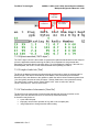
The following discussion describes the items in each radio’s line.
Radio’s
function
Radio’s
S/N or name
7.3.6 Radio’s Serial Number or Name (“Radio”)
“Radio” is the Serial Number or the name of the radio. See paragraph 7.2.1 for information on
toggling the Serial number/Name display. When the application discovers a radio, the radio is
named “New radio”.
See paragraph 3.7 for instructions on renaming radios.
Radio names and serial numbers are saved in the network file.
7.3.7 Radio’s function (“Fn”)
“Fn” is the function of the radio within the network.
M
S
Rn
Master Radio
Slave Radio
Repeater Radio (n is a number assigned by this application).
The application automatically assigns a number to each repeater. The numbers are assigned in
the order that the Diagnostic application detects each repeater. Although a radio may be
programmed to be a repeater, the radio will be indicated as a slave until the Diagnostic
application detects other radios that are linked through the radio into the network.
LUM0003AB Rev C
34 of 63
FreeWave Technologies
900MHz, 2.4GHz, and 1.4GHz Spread Spectrum Modem
Multipoint Diagnostics Manual V 2.16D
Radio link
noise level
Radio link
signal strength
7.3.8 Radio link signal strength (“Sig”)
“Sig” is the strength of the signal that the radio receives. For repeaters, “Sig” refers just to the
radio link towards the Master. The units are either standard (as they would be displayed in the
Radio Statistics Menu), or in dB!V. See paragraph 7.2.2 for information on Selecting Signal
Units.
For reliable radio performance under all conditions, the signal level should be at least 40 (in
standard units). (RSSI = Received Signal Strength Indicator.)
This signal
Master
Rep.
This signal
Slave
Master
This radio is
being described
Rep.
Slave
This radio is being
described
7.3.9 Radio link noise level (“Nse”)
Nse is the average level of the noise the radio receives when linked and not transmitting. The
units are the same as for the signal strength. For reliable radio performance under all conditions,
the “Nse” value should be at least 30 (in standard units) below the signal strength reading. If the
difference is less than 30, the application displays the value in red.
This noise
Master
Rep.
Slave
Not
transmitting
This radio is being
described
LUM0003AB Rev C
35 of 63
FreeWave Technologies
900MHz, 2.4GHz, and 1.4GHz Spread Spectrum Modem
Multipoint Diagnostics Manual V 2.16D
Radio
frequency
Receive
success
7.3.10 Receive success rate (“%”)
“%” is the percentage of data packets that the radio has successfully received on the first try. If
the radio is a repeater, the “%” refers to the radio link towards the Master. The value should be at
least 75%. If less than 75%, the application will highlight the value in red.
7.3.11 Radio frequency error (“Freq ppm”)
The PPM is the error of the radio’s frequency with respect to the Master. The value should be
within " 10 ppm. If the value exceeds " 5 ppm, the application will highlight the serial number in
red. If all the values are biased in one direction, the Master radio is where the frequency has
drifted. A radio with a high Frequency Error may need to be sent into FreeWave to be re-tuned.
LUM0003AB Rev C
36 of 63
FreeWave Technologies
900MHz, 2.4GHz, and 1.4GHz Spread Spectrum Modem
Multipoint Diagnostics Manual V 2.16D
Length of
radio link
Bytes
transmitted
Total number of
disconnects
7.3.12 Bytes transmitted (“DATA bytes”)
The “DATA bytes” column is the number of bytes that the radio has transmitted from the data port
(since the application started monitoring the radio). Since Repeaters do not generate data
themselves, but repeat data from another radio, a ‘0’ will be displayed. However, if the radio is a
Slave/Repeater, the count is for the data transmitted while operating as a Slave.
7.3.13 Length of radio link (“Dist”)
The Dist is the distance between the selected radio and the radio to which the selected radio is
directly linked. If the radio is linked directly to the Master, Dist is the distance to the Master.
Otherwise, Dist is the distance to the repeater to which the radio is linked. Distances greater than
1 km are typically accurate to within 30 meters. Shorter distances are not reported accurately.
The units are km or miles; use the “Show”/”Metric km/C” menu to select km, and the
“Show”/”American mi/F” menu to select miles.
7.3.14 Total number of disconnects (“Num Dis”)
The Num Dis is the total number of times that the selected radio has lost connection to the
network (since the radio was turned on or since Set-up mode was ended).
A disconnect may be due to:
! a poor radio link path,
! temporary removal from operation of any radio in the complete path,
! using Diagnostics to change another radio’s setting.
LUM0003AB Rev C
37 of 63
FreeWave Technologies
900MHz, 2.4GHz, and 1.4GHz Spread Spectrum Modem
Multipoint Diagnostics Manual V 2.16D
Repeater directly
linked to "Rep 1"
Repeater
directly linked
to this modem
Repeater directly
linked to "Rep 3"
Repeater directly
linked to "Rep 2"
Repeater's
'R' number
Repeater's received
signals strength
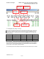
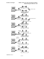
7.3.15 Repeater info (“Rep n” "N” "Sg”)
“Rep n N Sg” is the path that the radio uses to communicate to the Master. “Rep 1” refers to the
radio (Master or repeater) to which the radio is directly linked. “Rep 2” is the repeater (not the
master) to which “Rep 1” is directly linked, and so forth. Use the table below to see what each
column refers to.
# of repeaters
0
1
2
3
4
5+
“Rep1"”
Master
Repeater
Rep. closest to slave
Rep. closest to slave
Rep. closest to slave
Rep. closest to slave
“Rep2”
"Rep3"
"Rep4"
Other rep.
2nd rep.
2nd rep.
2nd rep.
3rd rep.
3rd rep.
3rd rep.
4th rep.
4th rep.
Up to 4 repeaters are shown (the 4 "closest" to the radio being displayed). The rest of the path
may also be derived: first observe which radio is listed under the "Rep 4" column (for example "R
5") then, in the "Fn" column, find that repeater ("R 5" for this example); that line will display the
rest of the path, from that repeater, towards the Master.
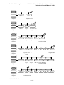
The next drawings show some examples of networks and how these networks may be numbered.
LUM0003AB Rev C
38 of 63
FreeWave Technologies
Master
Diagnostics
computer
Diagnostics
computer
Diagnostics
computer
Diagnostics
computer
Slave
"Rep 1"
This is the radio
being described
Master
Rep.
"Rep 2"
"Rep 1"
Master
Rep.
Rep.
Rep.
"Rep 4"
"Rep 3"
"Rep 2"
"Rep 1"
Master
Rep.
Rep.
Rep.
Rep.
Rep.
"Rep 3"
"Rep 2"
"Rep 1"
Rep.
Rep.
Diagnostics
computer
Diagnostics
computer
900MHz, 2.4GHz, and 1.4GHz Spread Spectrum Modem
Multipoint Diagnostics Manual V 2.16D
Slave
This is the radio
being described
Data on this "Rep 4"
repeater is not
shown
Master
Rep.
Rep.
Rep.
"Rep 4"
"Rep 3"
"Rep 2"
"Rep 1"
Master
Rep.
Rep.
Rep.
"Rep 1"
This is the radio
being described
LUM0003AB Rev C
39 of 63
Slave
This is the radio
being described
Slave
This is the radio
being described
Slave
This is the radio
being described
Rep.
Rep.
Slave
FreeWave Technologies
900MHz, 2.4GHz, and 1.4GHz Spread Spectrum Modem
Multipoint Diagnostics Manual V 2.16D
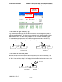
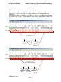
Each "Rep n" column has 2 items: "N" (number) and "Sg" (signal).
"N" is the number of the next repeater down the path. For example, 'N' = '1' refers to the radio
that has "R 1" in the "Fn" column. 'N' = '0' refers to the Master (in the top line, just above the
scroll bars).
Don't confuse repeater "R 1" with "Rep 1": repeater "R 1" is the 1st repeater that the application
found, while "Rep 1" is the 1st repeater down the path, from the radio towards the Master (not
necessarily the same location). The “N” digit will define the Fn location of the repeater.
"N"=0
"N"=1
"N" of Rep 1" is 1,
so "Rep 1" must be radio "R 1"
Master
Rep.
Slave
Rep1,
"R 1"
Looking at
modem #4
"N"=0
"N"=1
"N" of Rep 1" is 0,
So "Rep 1" must be the Master
Master
Rep1,
Master
Rep.
Looking at
radio #3, "R 1"
LUM0003AB Rev C
40 of 63
Slave
FreeWave Technologies
900MHz, 2.4GHz, and 1.4GHz Spread Spectrum Modem
Multipoint Diagnostics Manual V 2.16D
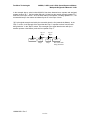
In the example above, serial number 906-0510 has been detected as a repeater and assigned
repeater number "R 1". Serial number 906-4441 is linked into the network through repeater "R 1"
as shown in the Rep1 column. All of the other radios in the network, including repeater "R 1", are
connected directly to the master as indicated by the '0' in the Rep1 column.
"Sg" is the signal strength received by the next radio down the line (towards the Master). In the
"Rep 1" column, is the strength of the signal that the "Rep 1" repeater receives from the radio
being looked at. In the "Rep2" column, is the strength of the signal that the next radio (be it
another repeater or the Master) receives from repeater "Rep 1".
"Sg" of
"Rp 2"
Master
"Sg" of
"Rp 1"
Rep.
Rep.
Rep2
Rep1
LUM0003AB Rev C
41 of 63
Slave
This is the radio
being described
FreeWave Technologies
900MHz, 2.4GHz, and 1.4GHz Spread Spectrum Modem
Multipoint Diagnostics Manual V 2.16D
Time of latest
diagnostics response
Diagnostics
response rate
7.3.16 Diagnostics response rate ("Poll %")
The Poll% is the percentage of the time the radio has reported back diagnostics data when
polled. If the radio is used to transmit a large amount of data as part of normal operation, the
radio will have less time to respond to the Master polling diagnostics data; in that case, the
diagnostics response rate will decrease. If the value is 0, it may be because the radio is
disconnected from the network.
7.3.17 Time of latest diagnostics response ("Time Rcvd")
The Time Rcvd is the time (measured using the System Clock) when the radio last replied to
diagnostics polling. If the lag in response exceeds the Alarm Time (see "Alarm Time" below,
paragraph 7.3.19), the application highlights Time Rcvd in red.
LUM0003AB Rev C
42 of 63
FreeWave Technologies
Number of
Radios
900MHz, 2.4GHz, and 1.4GHz Spread Spectrum Modem
Multipoint Diagnostics Manual V 2.16D
Alarm time
Poll status indicators: ignore
7.3.18 Number of Radios ("Number of Radios")
The Number of Radios is the total number of radios in the list, not counting the Master. (A radio
may be listed even if the radio is no longer in the network, as radios must be deleted from the list
manually.)
7.3.19 Alarm Time
The Alarm Time is the maximum acceptable time without a diagnostics response from a given
radio (see "Time of latest diagnostics poll" above, paragraph 7.3.17). After that time, the
application highlights in red the radio's "Time Rcvd" time. The default is 60 seconds. Use the '+'
and '-' keys of the computer's numeric keypad to change the value.
7.3.20 Poll Status Indicators
The counters and indexes displayed on the lower right corner of the display are troubleshooting
indicators for use by FreeWave Technologies. They serve no purpose in the Diagnostic
application other than to provide an indication that the program is running correctly. One of the
indicators will display Random or Sequen depending on the polling method that is active, either
random or sequential. If Sequen is displayed, the number indicates which radio number in the list
is currently being polled. The number display next to the indicator indicates where the diagnostic
program is in the polling process.
LUM0003AB Rev C
43 of 63
FreeWave Technologies
7.4
900MHz, 2.4GHz, and 1.4GHz Spread Spectrum Modem
Multipoint Diagnostics Manual V 2.16D
Reading Screen 1
Screen 1 is very similar to "Screen 0". Screen 1 provides additional information about the radios,
such as the status of the data port lines (RS-232 only) and information on the operating
environment. Some fields in screen 1 are the same as in "Screen 0", the following section
describes only the fields that are unique to "Screen 1". (For information on the other fields, see
Section 7.3.)
Supply
voltage.
Firmware rev.
Modem
temperature
Radio ID
7.4.1 Radio ID ("ID")
“ID” is the radio ID that was set in the radio's programming ("multipoint settings" menu, 'D' submenu). The ID may be used to identify the radio's site or to track a device connected to it. The
default is 65535.
7.4.2 Firmware Revision ("Rev")
“Rev” is an indirect indication of the version of the firmware installed in this radio. FreeWave
technical support can convert the Rev number to the actual revision level.
7.4.3 Radio temperature ("Temp")
“Temp” is the operating temperature of the radio. The units are degrees Celsius (default) or
Fahrenheit; use the "Show"/"Metric km/C" option to select Celsius, and the “Show"/"American
mi/F" option to select Fahrenheit. All FreeWave radios are 100% tested for operation over a
temperature range of –40 C to +75C (-40F to +167F).
LUM0003AB Rev C
44 of 63
FreeWave Technologies
900MHz, 2.4GHz, and 1.4GHz Spread Spectrum Modem
Multipoint Diagnostics Manual V 2.16D
7.4.4 Supply voltage ("Vtg")
“Vtg” is the supply voltage of the radio, in Volts.
State of the
CTS output
State of the
RTS input
State of the
DTR input
Number of
diagnostics
requests
received
7.4.5 State of RS232 port lines ("RTS", "CTS", "DTR")
“RTS”, “CTS”, and “DTR” refer to the states of the RTS, and DTR inputs and the CTS output of
the radio's Data Port. 'H" refers to a high state (~ 10 V, asserted, logic '0') and 'L' refers to a low
state (~-10 V, deasserted, logic '1'). Note that in inverted-TTL models, the screen reports '0' if the
line is high (5 V) and vice versa.
In RS485 radios only the state of the DTR input is reported.
In Ethernet radios there are no such inputs, so these reports are invalid.
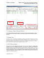
7.4.6 Number of diagnostics requests received ("Polls Rcvd")
“Polls Rcvd” is the total number of replies to diagnostic polling that the master received from the
radio, since the application started. (In a multipoint network, a master may miss some messages
from another radio.)
LUM0003AB Rev C
45 of 63
FreeWave Technologies
7.5
900MHz, 2.4GHz, and 1.4GHz Spread Spectrum Modem
Multipoint Diagnostics Manual V 2.16D
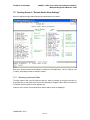
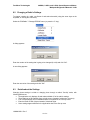
Reading Screen 2: "Remote Radio Setup Settings"
Screen 2 displays a single radio's settings and allows them to be edited.
Note: If the firmware version of the Master is earlier than 5.68 (900 MHz), 1.60 (2.4 GHz) or 9.34
(1.4GHz), the settings cannot be edited or viewed.
7.5.1 Selecting a particular Radio
To select another radio, scroll through the radio list, either by clicking on the gray scroll bars, or
by pressing the up and down arrow keys on the diagnostics computer. When either end of the list
is reached, the list restarts from the opposite end.
At the top of the screen, the Serial Number and the radio’s name are displayed.
LUM0003AB Rev C
46 of 63
FreeWave Technologies
900MHz, 2.4GHz, and 1.4GHz Spread Spectrum Modem
Multipoint Diagnostics Manual V 2.16D
Serial number and
name of this modem
"UP" scroll bar
At the bottom, the screen displays the order of the radio within the radio list (of the previous
screens). Specifically, '0' refers to the Master.
Setting presently
being updated
"DOWN" scroll bar
Order of this modem
in the modem list
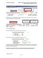
7.5.2 Settings' display
Initially, the application uses "XXX" for the value of each setting.
As the radio reports a setting, the application displays the value.
The process is slower if the network is transferring a lot of data. Pressing 'P' on the diagnostics
computer keyboard will force the radio to respond quicker, as this sends a poll request to that
specific radio for all of its settings.
Each setting is marked with a number, 0 to 40. (Screen 2 handles only the most important 35
settings.) At the bottom right, the screen shows which setting is presently being updated.
LUM0003AB Rev C
47 of 63
FreeWave Technologies
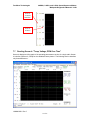
7.6
900MHz, 2.4GHz, and 1.4GHz Spread Spectrum Modem
Multipoint Diagnostics Manual V 2.16D
Reading Screen 3, Signal Quality over Time
Screen 3 displays a rolling graph of the performance over time of a single radio.
7.6.1 Selecting a particular Radio
To select another radio, scroll through the radio list, either by clicking on the gray scroll bars, or
by pressing the up and down arrow keys on the keyboard. When either end of the list is reached,
the list will restart from the opposite end.
At the top left, the screen displays the Serial Number of the selected radio, and the order of the
radio within the radio list (of the '0' and '1' screens). Specifically, '0' refers to the Master.
At the top right, the screen displays the name of the selected radio, and the Radio ID.
LUM0003AB Rev C
48 of 63
FreeWave Technologies
900MHz, 2.4GHz, and 1.4GHz Spread Spectrum Modem
Multipoint Diagnostics Manual V 2.16D
Serial number
of this radio
Name assigned
to this radio
Order of this radio in
the radio list
Radio ID of this
radio
"UP" scroll bar
"DOWN" scroll bar
7.6.2 Horizontal time scale
The application starts gathering data when first started. The software displays the data starting
from the right edge, and then rolls to the left. The right edge of the graph is always "now". Each
time the traces reach the left end, the application changes the horizontal time scale by a factor of
2, so that all the data is displayed in a single screen. The numbers at the top of the graph indicate
the horizontal time scale (in minutes or hours); '0' is on the right, representing 0 hours (or
minutes) ago.
Now
Units
Horizontal
time scale
Total number of data
points gathered
LUM0003AB Rev C
49 of 63
FreeWave Technologies
900MHz, 2.4GHz, and 1.4GHz Spread Spectrum Modem
Multipoint Diagnostics Manual V 2.16D
7.6.3 Variables displayed
The graph plots 5 variables:
! "Receive %": the percentage of packets that are successfully received the first time
! "Signal Lv": the signal strength, in standard units (dB!V is not available)
! "Noise Lv": the background noise level, in standard units
! "Transmit Data Rate": the number of kilobytes that the radio transmits*, per seconds
! "Bad Pckts": portion of packets received that are bad
* For repeaters, this is only that data that is locally generated (non-zero only when a
Slave/Repeater is operating as a Slave). Repeaters with older firmware also include the data that
is repeated through them.
Percentage of packets that are successfully
received the first time (blue)
Signal strength, in standard units (green)
Overall maximum
Background noise level, in standard units
(red)
Overall average
Overall minimum
Number of kilobytes that this radio
transmits*, per seconds (gold)
Total number of bad packets received
(orange)
The first 3 variables display the overall minimum, maximum and average.
7.6.4 Vertical scale
The graph has 2 vertical scales. The gold colored scale ("0.0K“ to "4.0K") is for the Transmit Data
Rate. The black scale ("0" to "100") is for all the other variables.
LUM0003AB Rev C
50 of 63
FreeWave Technologies
900MHz, 2.4GHz, and 1.4GHz Spread Spectrum Modem
Multipoint Diagnostics Manual V 2.16D
Scale for
"Transmit
Data Rate"
Scale for
all others
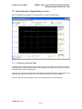
7.7
Reading Screen 4: "Temp, Voltage, PPM Over Time"
Screen 4 displays a rolling graph of the operating parameters over time of a single radio. Screen
4 is similar to Screen 3, except for the variables that are plotted. The following section describes
only those differences. .
LUM0003AB Rev C
51 of 63
FreeWave Technologies
900MHz, 2.4GHz, and 1.4GHz Spread Spectrum Modem
Multipoint Diagnostics Manual V 2.16D
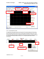
7.7.1 Variables displayed
The graph plots 5 variables:
! "Radio PPM": Error in the radio's radio frequency with respect to the Master [ppm]
! "Radio Vtg": the voltage of the radio's power supply {Volts]
! "RadioTemp": the temperature of the radio [C]
Error in the modem's radio frequency with
respect to the Master (blue)
Overall maximum
Modem supply voltage (green)
Overall minimum
Modem temperature (red)
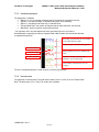
7.7.2 Vertical scale
The graph has 3 vertical scales. The green scale (0 to 15) is for the voltage of the radio's power
supply [Volts]. The blue scale (-15 to 15) is for the error in the radio's radio frequency [parts per
million]. The red scale (-50 to 75) is for the temperature of the radio [degrees Celsius].
Modem supply voltage [Volts] (green)
Error in the modem's radio frequency
[parts per million] (blue)
Modem temperature [degrees C] (red)
LUM0003AB Rev C
52 of 63
FreeWave Technologies
8
900MHz, 2.4GHz, and 1.4GHz Spread Spectrum Modem
Multipoint Diagnostics Manual V 2.16D
Editing the Radio's Settings
The selected radio's settings can be edited through Screen 2.
Only one setting can be changed at a time. FreeWave strongly recommends that the normal
data flow through a radio be interrupted while changing any settings using diagnostics.
8.1
Strategy
FreeWave recommends that the radio not be used to transfer data until all settings changes are
complete. The reason is because the radio disconnects from the network when settings are
changed. Afterwards, if the radio is able to reestablish the link, it will do so automatically.
Tip: To see whether or not a radio is connected, go to Screen 0 and look at the
"Time Rcvd" field, to see when the radio last sent diagnostics data.
Time of latest
diagnostics response
All changes should be verified before another change is made.
Certain settings must match throughout the entire network. These settings must be changed in
every radio in the network. Start from the Slaves, and work inward toward the Master; if a
repeater is changed before all the slaves beyond it are changed, the "outer" radios will lose the
link and not be able to reconnect once the master is reconfigured.
Verify each change before attempting to change a different setting.
LUM0003AB Rev C
53 of 63
FreeWave Technologies
900MHz, 2.4GHz, and 1.4GHz Spread Spectrum Modem
Multipoint Diagnostics Manual V 2.16D
Rep.
Diagnostics
computer
Slave
Edit a Slave first
Master
Rep.
Slave
This link
breaks
Rep.
Diagnostics
computer
Slave
Master
Edit another Slave
Rep.
Slave
Edit this repeater next
Rep.
Diagnostics
computer
Master
This link
breaks
Rep.
Slave
This link
breaks
Diagnostics
computer
Slave
Rep.
Slave
Edit this repeater next
Master
Rep.
Slave
Rep.
Slave
Rep.
Slave
Rep.
Slave
Rep.
Slave
Edit the
Master last
Diagnostics
computer
Master
This link
breaks
The links
restart
Diagnostics
computer
Master
LUM0003AB Rev C
54 of 63
FreeWave Technologies
8.2
900MHz, 2.4GHz, and 1.4GHz Spread Spectrum Modem
Multipoint Diagnostics Manual V 2.16D
Changing a Radio's Settings
To change a setting in a radio, use Screen 2 and select that radio (using the arrow keys on the
keyboard, or clicking the scroll bars).
Select the "EditRadio" / "Change EPROM" menu (or press the 'C' key).
A dialog appears.
Enter the number of the setting that is going to be changed (0 to 40) and click "OK".
A new dialog appears.
Enter the new value of the setting and click "OK"
8.3
Details about the Settings
Changing these settings is similar to changing them through a radio's "Set-Up" mode, with
following differences.
! The application only displays 40 and makes editable 35 of the radio's settings.
! These settings are all available from a single screen (instead of a hierarchy of menus)
! Five of these settings are not editable and are not reported in the "Set-up" mode.
! Enter the Radio ID with 3 bytes instead of 4 decimal digits.
! Some settings appear different in the Application than in the Set-up menu
LUM0003AB Rev C
55 of 63
FreeWave Technologies
900MHz, 2.4GHz, and 1.4GHz Spread Spectrum Modem
Multipoint Diagnostics Manual V 2.16D
Please refer to the Main Manual for an explanation of the significance of each setting displayed in
the screen, and what values are acceptable for each setting.
8.3.1 Risky changes
Changing certain parameters through Diagnostics is somewhat risky, as communication may be
lost. Therefore, a change may not be undone without going to the remote site to correct the
offending entry by use of direct access to the radio through "Set-Up" mode.
8.3.2 Xtal tune / SlicerThreshold / Frequency
These 3 settings report data that are not editable and are not even reported in the normal "Setup" mode. They are not described either here or in the Main Manual. They are only useful to a
FreeWave Technologies technician.
LUM0003AB Rev C
56 of 63
FreeWave Technologies
900MHz, 2.4GHz, and 1.4GHz Spread Spectrum Modem
Multipoint Diagnostics Manual V 2.16D
8.3.3 Settings that appear different from the Set-UP menu
The following settings relate directly to the settings in Set-Up mode however, they are displayed
differently. See the Main Manual for information of what these settings mean. Described here is
how they differ from the Set-Up menu:
8.3.3.1
Baud Rate
Baud rate is set using two parameters: 1- Baud Rate and 2- Baud High Byte.
Diagnostics setting
Baud Rate
Set-up Menu
setting
2- Baud High Byte
1- Baud Rate
1200
9
1
128
2400
8
0
192
4800
7
0
96
9600
6
0
48
19200
5
0
24
38400
4
0
12
57600
3
0
8
76800
2
0
6
115200
1
0
4
230400
0
0
2
8.3.3.2
RS232 Mode
Data Bits, Parity, Stop Bits
8,None, 1
7,Even, 1
7, Odd, 1
8, None, 2
8, Even, 1
8, Odd, 1
8.3.3.3
Set-up Menu setting
0
1
2
3
4
5
Diagnostics setting
0
2
3
16
18
19
MODBus RTU
MODBus RTU
Enabled
Disabled
Set-up Menu setting
1
0
LUM0003AB Rev C
57 of 63
Diagnostics setting
0
255
FreeWave Technologies
8.3.3.4
Xmit Power
Set Up
0
1
2
3
4
5
6
7
8
9
10
8.3.3.5
Diagnostics
0
16
32
48
64
80
96
112
128
144
160
RTS/CTS Control
RTS/CTS Control
Enabled
Disabled
8.3.3.6
8.3.3.8
Set-up Menu setting
1
0
Diagnostics setting
255
0
Set-up Menu setting
1
0
Diagnostics setting
255
0
Set-up Menu setting
0
1
2
Diagnostics setting
255
1
2
3
3
…
…
63
63
Set-up Menu setting
1
0
Diagnostics setting
255
0
Repeater Freq
Repeater Frequency
Enabled
Disabled
8.3.3.7
900MHz, 2.4GHz, and 1.4GHz Spread Spectrum Modem
Multipoint Diagnostics Manual V 2.16D
Low Power
Repeater Frequency
Disabled
LEDs dimmed
LEDs dimmed, radio sleeps
every other slot
LEDs dimmed, radio sleeps
2 of 3 slots
LEDs dimmed, radio sleeps
number of slots
corresponding to setting.
LEDs dimmed, radio sleeps
62 of 63 slots.
PPS Enable
PPS Enable
Enabled
Disabled
LUM0003AB Rev C
58 of 63
FreeWave Technologies
8.3.3.9
900MHz, 2.4GHz, and 1.4GHz Spread Spectrum Modem
Multipoint Diagnostics Manual V 2.16D
Slave/Repeater
Slave Repeater
Enabled
Disabled
Set-up Menu setting
1
0
Diagnostics setting
0
255
Set-up Menu setting
1
0
Diagnostics setting
0
255
8.3.3.10 Master Sync
Master Sync
Enabled
Disabled
8.3.3.11 Network ID
Network ID
Set-up Menu setting
Diagnostics setting
High Byte
Low Byte
0 to 255
Network ID
255
Network ID
256 to 511
Network ID
0
Network ID - 256
512 to 767
Network ID
1
Network ID - 512
768 to 1023
Network ID
2
Network ID - 768
1024 to 1279
Network ID
3
Network ID - 1024
1280 to 1535
Network ID
4
Network ID - 1280
1536 to 1791
Network ID
5
Network ID - 1536
1792 to 2047
Network ID
6
Network ID - 1792
2048 to 2303
Network ID
7
Network ID - 2048
2304 to 2559
Network ID
8
Network ID - 2304
2560 to 2815
Network ID
9
Network ID - 2560
2816 to 3071
Network ID
10
Network ID - 2816
3072 to 3327
Network ID
11
Network ID - 3072
3328 to 3583
Network ID
12
Network ID - 3328
3584 to 3839
Network ID
13
Network ID - 3584
3840 to 4095
Network ID
14
Network ID - 3840
Note: Radios with firmware versions earlier than 5.68 (900 MHz) or 1.62 (2.4 GHz) will not accept
Network ID values larger than 255. The entry into the Low Byte up to 255 is the number that is
desired for the Network ID. For Network ID’s above 255 set the High Byte accordingly and
subtract the stated value from the desired Network ID number. e.g. A network ID of 2000 is
desired. Set the High Byte to 6 and the Low Byte will equal (2000-1792) 208.
LUM0003AB Rev C
59 of 63
FreeWave Technologies
900MHz, 2.4GHz, and 1.4GHz Spread Spectrum Modem
Multipoint Diagnostics Manual V 2.16D
8.3.3.12 SubNet ID
SubNet ID
Rcv & Xmit = 01h to FFh
Set-up Menu setting
Rcv 1-F, Xmit 1-F
Diagnostics setting
1 to 255
Transmit Subnet ID (_X)
Diagnostics requires that the Subnet be entered as a decimal number. The 2 values of the
Receive and Xmit settings are loaded as one byte into the EPROM. The table below shows the
correlation of how to calculate the proper value to load into the diagnostic location.
For example, if the value desired in the Set-Up menu is Rcv = E and Xmit = 3. The corresponding
decimal number will be 62. Enter 62 into the SubNet ID setting. Please note that a setting of 255
(Rcv = F and Xmit = F) will set the SubNet ID to Disabled.
0
1
2
3
4
5
6
7
8
9
A
B
C
D
E
F
0
N/A
16
32
48
64
80
96
112
128
144
160
176
192
208
224
240
1
1
17
33
49
65
81
97
113
129
145
161
177
193
209
225
241
2
2
18
34
50
66
82
98
114
130
146
162
178
194
210
226
242
3
3
19
35
51
67
83
99
115
131
147
163
179
195
211
227
243
4
4
20
36
52
68
84
100
116
132
148
164
180
196
212
228
244
Receive Subnet ID (X_)
5
6
7
8
9
5
6
7
8
9
21
22
23
24
25
37
38
39
40
41
53
54
55
56
57
69
70
71
72
73
85
86
87
88
89
101 102 103 104 105
117 118 119 120 121
133 134 135 136 137
149 150 151 152 153
165 166 167 168 169
181 182 183 184 185
197 198 199 200 201
213 214 215 216 217
229 230 231 232 233
245 246 247 248 249
A
10
26
42
58
74
90
106
122
138
154
170
186
202
218
234
250
B
11
27
43
59
75
91
107
123
139
155
171
187
203
219
235
251
C
12
28
44
60
76
92
108
124
140
156
172
188
204
220
236
252
D
13
29
45
61
77
93
109
125
141
157
173
189
205
221
237
253
8.3.3.13 Radio ID
The Diagnostics Application allows any number below 2^24 to be set. While the radio's Set-up
mode will display the entire number, Diagnostics will only let numbers up to 9999 be entered.
Radio ID
0 to
255
256 to
9999
10000 to
65535
65536 to
16777215
Set-up Menu setting
Radio ID
Super Byte
0
Radio ID
0
Not available
0
Not available
INT(Radio ID /
65535)
The Radio ID must be set using 3 entries:
! Super byte: "33 Radio ID Super".
! High byte: "29 Radio ID High".
! Low byte: "30 Radio ID Low".
LUM0003AB Rev C
60 of 63
Diagnostics setting
High Byte
0
Low Byte
Radio ID
INT((Radio ID
MOD 65535) / 256)
INT((Radio ID
MOD 65535) / 256)
INT((Radio ID
MOD 65535) / 256)
Radio ID MOD
256
Radio ID MOD
256
Radio ID MOD
256
E
14
30
46
62
78
94
110
126
142
158
174
190
206
222
238
254
F
15
31
47
63
79
95
111
127
143
159
175
191
207
223
239
255
FreeWave Technologies
900MHz, 2.4GHz, and 1.4GHz Spread Spectrum Modem
Multipoint Diagnostics Manual V 2.16D
Each entry uses a value between 0 and 255.
Radio ID = 65535 * Super byte + 256 * High byte + Low byte.
8.3.3.14 32 Diagnostics
Diagnostics
Enabled
Disabled
9
Set-up Menu setting
1 to 63
0
Diagnostics setting
1 to 63
255
Ending the session
Saving the information gathered through the session may be a good idea if it has not already
been saved previously. See paragraph 5.4 Saving Network File and paragraph 6.2 Saving Data
for further information.
When done, communication with the Master must be ended.
If the communication was directly through the serial port, close the port with the "Communication"
/ "Close Comm" menu.
If the communication was directly through an Ethernet Network (either TCP/IP or UDP/IP), close
the connection with the "Communication" / "Close TCP/UPD" menu.
LUM0003AB Rev C
61 of 63
FreeWave Technologies
900MHz, 2.4GHz, and 1.4GHz Spread Spectrum Modem
Multipoint Diagnostics Manual V 2.16D
Quit the application with the "File" / "Exit" menu or press alt-F4 or alt-F-X.
LUM0003AB Rev C
62 of 63
FreeWave Technologies
900MHz, 2.4GHz, and 1.4GHz Spread Spectrum Modem
Multipoint Diagnostics Manual V 2.16D
10 Troubleshooting
To run the diagnostic program, make sure that:
! The network is Point-to-multipoint.
! The Diagnostics computer is able to access the FreeWave network
o either through its Master (through a Diagnostics Cable)
o or through the Internet.
! The Diagnostics application is installed and running on the Diagnostic computer.
! The Diagnostics setting in the Master radio is set to a value between 1 and 63, inclusive.
LUM0003AB Rev C
63 of 63