1
DELTAplus Meter
User’s Manual
Rev C
ABB Automation Technologies AB
P.O. Box 1005
SE-611 29 NYKÖPING
Sweden
Tel: +46 - 155 295000
Fax: +46 - 155 288110
Page 1 of 137
DELTAplus meter User’s Manual Rev C
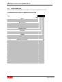
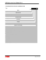
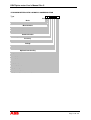
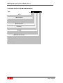
TABLE OF CONTENTS
TABLE OF CONTENTS
1
GENERAL ............................................................................................................ 6
2
PRODUCT DESCRIPTION .................................................................................. 7
2.1
FAMILY OVERVIEW ............................................................................................................................. 7
2.2
METER PARTS ........................................................................................................................................ 8
2.3
METER TYPES ........................................................................................................................................ 9
2.3.1
NETWORK TYPE............................................................................................................................ 10
2.3.2
TYPE DESIGNATION..................................................................................................................... 11
2.4
ENERGY INDICATOR ......................................................................................................................... 15
2.5
BUTTONS................................................................................................................................................ 15
2.5.1.1 SET BUTTON .............................................................................................................................. 15
2.5.1.2 SCROLL BUTTON / LIGHT SENSOR ....................................................................................... 15
2.6
DISPLAY INFORMATION................................................................................................................... 16
2.6.1
DISPLAY OVERVIEW.................................................................................................................... 17
2.6.2
VOLTAGE INDICATORS............................................................................................................... 17
2.6.3
OK AND ERROR SYMBOLS ......................................................................................................... 17
2.6.4
7-SEGMENT 7 CHARACTERS AND UNIT .................................................................................. 18
2.6.5
INDICATION OF ACTIVE TARIFF ............................................................................................... 18
2.6.6
LOAD INDICATOR......................................................................................................................... 18
2.7
DISPLAY MODES.................................................................................................................................. 19
2.7.1
NORMAL MODE............................................................................................................................. 19
2.7.1.1 Energy display in Normal mode.................................................................................................... 20
2.7.2
ALTERNATIVE MODE .................................................................................................................. 20
2.7.2.1 LCD test ........................................................................................................................................ 21
2.7.2.2 Error information .......................................................................................................................... 21
2.7.2.3 Energy display in Alternative mode .............................................................................................. 21
2.7.2.4 Transformer ratio .......................................................................................................................... 21
2.7.2.5 Pulse output frequency .................................................................................................................. 21
2.7.2.6 Baud rate ....................................................................................................................................... 22
2.7.2.7 Primary address ............................................................................................................................. 22
2.7.2.8 Communication status ................................................................................................................... 22
2.7.2.9 LED reactive ................................................................................................................................. 22
2.7.2.10
Input counter(s) ......................................................................................................................... 22
2.7.2.11
Input status ................................................................................................................................ 22
2.7.2.12
Input stored status...................................................................................................................... 22
2.7.2.13
Date ........................................................................................................................................... 22
2.7.2.14
Time .......................................................................................................................................... 23
2.7.2.15
Write protection level................................................................................................................ 23
2.7.3
INSTRUMENTATION MODE........................................................................................................ 23
2.7.3.1 Power ............................................................................................................................................ 23
2.7.3.2 Voltage .......................................................................................................................................... 23
2.7.3.3 Current .......................................................................................................................................... 24
2.7.3.4 Power factor .................................................................................................................................. 24
2.7.3.5 Active quadrant ............................................................................................................................. 24
2.7.3.6 Frequency...................................................................................................................................... 24
2.7.3.7 Current harmonics ......................................................................................................................... 24
2.7.4
SET MODE....................................................................................................................................... 25
2.7.4.1 Current transformer ratio (CT) ...................................................................................................... 25
2.7.4.2 Voltage transformer ratio (VT) ..................................................................................................... 26
Page 2 of 137
DELTAplus meter User’s Manual Rev C
2.7.4.3
2.7.4.4
2.7.4.5
2.7.4.6
2.7.4.7
2.7.4.8
2.7.4.9
2.8
TABLE OF CONTENTS
Pulse output frequency .................................................................................................................. 26
Reset of energy registers ............................................................................................................... 27
Primary address ............................................................................................................................. 27
Baud rate ....................................................................................................................................... 28
Time .............................................................................................................................................. 28
Date ............................................................................................................................................... 30
Communication write access level ................................................................................................ 31
INSTRUMENTATION........................................................................................................................... 32
2.9
INPUTS AND OUTPUTS....................................................................................................................... 33
2.9.1
FUNCTIONALITY OF INPUTS...................................................................................................... 33
2.9.2
FUNCTIONALITY OF OUTPUTS.................................................................................................. 34
2.10 TARIFF INPUTS .................................................................................................................................... 34
2.10.1
CONNECTIONS............................................................................................................................... 34
2.10.2
INDICATION OF ACTIVE TARIFF ............................................................................................... 34
2.10.3
INPUT CODING .............................................................................................................................. 34
2.11 PULSE OUTPUTS .................................................................................................................................. 35
2.11.1
PULSE FREQUENCY AND PULSE LENGTH .............................................................................. 35
2.12 INTERNAL CLOCK AND TIME DEPENDANT FUNCTIONS....................................................... 36
2.12.1
INTERNAL CLOCK ........................................................................................................................ 36
2.12.2
MONTHLY VALUES ...................................................................................................................... 36
2.12.3
LOAD PROFILE .............................................................................................................................. 37
2.12.4
MAXIMUM DEMAND.................................................................................................................... 38
2.12.5
EVENT LOG .................................................................................................................................... 39
2.12.6
TARIFF CONTROL BY CLOCK .................................................................................................... 39
2.12.7
OUTPUTS CONTROL BY CLOCK ................................................................................................ 40
2.13 ELECTRONICS...................................................................................................................................... 41
2.13.1
MAIN BOARD ................................................................................................................................. 41
2.13.2
INPUT/OUTPUT BOARDS ............................................................................................................. 42
2.13.3
COMMUNICATION BOARDS....................................................................................................... 43
2.14
DELTAPLUS MEASUREMENT METHODS..................................................................................... 44
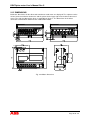
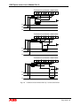
2.15
DIMENSIONS ......................................................................................................................................... 45
3
TECHNICAL DATA............................................................................................ 46
3.1
DIRECT CONNECTED METER ......................................................................................................... 46
3.1.1
VOLTAGE/CURRENT INPUTS ..................................................................................................... 46
3.1.2
GENERAL DATA ............................................................................................................................ 46
3.1.3
MECHANICAL DATA AND TESTS.............................................................................................. 46
3.1.4
ENVIRONMENT DATA AND TESTS ........................................................................................... 46
3.1.5
PULSE OUTPUT (STANDARD ON ALL METERS EXCEPT LON, MBUS) .............................. 46
3.1.6
VISIBLE PULSE INDICATOR ....................................................................................................... 46
3.1.7
STANDARDS................................................................................................................................... 47
3.1.8
ELECTROMAGNETIC COMPATIBILITY (EMC) AND INSULATION PROPERTIES............. 47
3.2
TRANSFORMER RATED METER ..................................................................................................... 47
3.2.1
VOLTAGE INPUTS......................................................................................................................... 47
3.2.2
CURRENT INPUTS ......................................................................................................................... 47
3.2.3
GENERAL DATA ............................................................................................................................ 47
3.2.4
MECHANICAL DATA AND TESTS.............................................................................................. 47
3.2.5
ENVIRONMENT DATA AND TESTS ........................................................................................... 48
3.2.6
PULSE OUTPUT (STANDARD ON ALL METERS EXCEPT LON, MBUS) .............................. 48
Page 3 of 137
DELTAplus meter User’s Manual Rev C
3.2.7
3.2.8
3.2.9
3.2.10
TABLE OF CONTENTS
TRANSFORMER RATIOS.............................................................................................................. 48
VISIBLE PULSE INDICATOR ....................................................................................................... 48
STANDARDS................................................................................................................................... 48
ELECTROMAGNETIC COMPATIBILITY (EMC) AND INSULATION PROPERTIES............. 48
3.3
OPTIONS................................................................................................................................................. 48
3.3.1
INPUTS............................................................................................................................................. 48
3.3.2
OUTPUTS......................................................................................................................................... 49
3.3.3
INTERNALCLOCK ......................................................................................................................... 49
4
INSTALLATION ................................................................................................. 50
4.1
MOUNTING............................................................................................................................................ 50
4.1.1
DIN-RAIL MOUNTED .................................................................................................................... 50
4.1.2
WALL MOUNTED .......................................................................................................................... 50
4.1.3
FLUSH MOUNTED ......................................................................................................................... 51
4.2
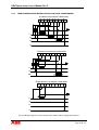
WIRING DIAGRAMS............................................................................................................................ 52
4.2.1
DIRECT CONNECTED METERS................................................................................................... 52
4.2.2
TRANSFORMER RATED METERS WITHOUT VOLTAGE TRANSFORMER......................... 53
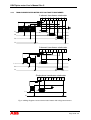
4.2.3
TRANSFORMER RATED METER WITH VOLTAGE TRANSFORMER ................................... 54
4.2.4
INPUTS/OUTPUTS.......................................................................................................................... 55
4.2.5
TARIFF INPUTS .............................................................................................................................. 55
4.2.6
PULSE OUTPUTS............................................................................................................................ 55
4.2.7
COMMUNICATION........................................................................................................................ 55
4.3
INSTALLATION TEST ......................................................................................................................... 55
4.3.1
TEST PROCEDURE ........................................................................................................................ 56
4.3.1.1 Phase voltage presence test ........................................................................................................... 56
4.3.1.2 Phase connected to neutral test...................................................................................................... 56
4.3.1.3 Power measurement ...................................................................................................................... 56
4.3.2
ERROR CODES ............................................................................................................................... 57
5
MEASUREMENT METHODS............................................................................. 58
5.1
ACTIVE AND REACTIVE POWER.................................................................................................... 58
5.2
SINGLE PHASE METERING .............................................................................................................. 60
5.3
3-PHASE 2-ELEMENT METERING................................................................................................... 61
5.4
3-PHASE 3-ELEMENT METERING................................................................................................... 65
5.5
SUMMATION......................................................................................................................................... 68
6
COMMUNICATION ............................................................................................ 69
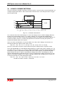
6.1
M-BUS...................................................................................................................................................... 70
6.1.1
COMMUNICATION OBJECTS ...................................................................................................... 70
6.1.2
PHYSICAL INTERFACE ................................................................................................................ 71
6.1.2.1 Optical interface ............................................................................................................................ 71
6.1.2.2 Optional board............................................................................................................................... 71
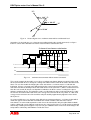
6.1.3
PROTOCOL DESCRIPTION........................................................................................................... 72
6.1.3.1 Telegram formats .......................................................................................................................... 72
6.1.3.1.1 Field descriptions ................................................................................................................... 73
6.1.3.2 Communication process ................................................................................................................ 79
6.1.3.2.1 Selection and Secondary Addressing...................................................................................... 79
6.1.4
TELEGRAMS................................................................................................................................... 80
Page 4 of 137
DELTAplus meter User’s Manual Rev C
TABLE OF CONTENTS
6.1.4.1 Examples of telegram 1-4 readouts ............................................................................................... 82
6.1.4.2 Sending data to the meter .............................................................................................................. 87
6.1.4.2.1 Set tariff.................................................................................................................................. 87
6.1.4.2.2 Set primary address ................................................................................................................ 87
6.1.4.2.3 Change baud rate .................................................................................................................... 87
6.1.4.2.4 Reset power fail counter ......................................................................................................... 87
6.1.4.2.5 Set current transformer (CT) ratio .......................................................................................... 87
6.1.4.2.6 Set voltage transformer (VT) ratio ......................................................................................... 87
6.1.4.2.7 Set transformer ratio (CT*VT) ............................................................................................... 87
6.1.4.2.8 Select status information ........................................................................................................ 87
6.1.4.2.9 Reset of stored state for input 1 .............................................................................................. 87
6.1.4.2.10 Reset of stored state for input 2 ............................................................................................ 87
6.1.4.2.11 Reset of input counter 1........................................................................................................ 87
6.1.4.2.12 Reset of input counter 2........................................................................................................ 87
6.1.4.2.13 Set output 1........................................................................................................................... 87
6.1.4.2.14 Set output 2........................................................................................................................... 87
6.1.4.2.15 Reset of power outage time .................................................................................................. 87
6.1.4.2.16 Send password ...................................................................................................................... 87
6.1.4.2.17 Set password......................................................................................................................... 87
6.1.4.2.18 Set date and time .................................................................................................................. 87
6.1.4.2.19 Set date ................................................................................................................................. 87
6.1.4.2.20 Reset maximum demand, monthly values, load profile or event log.................................... 87
6.1.4.2.21 Freeze maximum demand..................................................................................................... 87
6.1.4.2.22 Set write access level............................................................................................................ 87
6.1.4.2.23 Set tariff source..................................................................................................................... 87
6.1.4.2.24 Suppress LCD error display ................................................................................................. 87
6.1.4.3 Reading data from the meter that require a read request command .............................................. 87
6.1.4.3.1 Read request and readout of load profile data ........................................................................ 87
6.1.4.3.2 Read request and readout of maximum demand data ............................................................. 87
6.1.4.3.3 Read request and readout of monthly values .......................................................................... 87
6.1.4.3.4 Read request and readout of event log data ............................................................................ 87
6.1.4.3.5 Read request and readout of current harmonics...................................................................... 87
6.1.4.4 Error/Information flags ................................................................................................................. 87
6.1.5
INSTALLATION.............................................................................................................................. 87
6.2
LONWORKS........................................................................................................................................... 87
6.2.1
TECHNICAL DATA (ADDITIONS TO THE BASIC METER)..................................................... 87
6.2.1.1 Communication objects................................................................................................................. 87
6.2.2
COMMISSIONING/OPERATION................................................................................................... 87
6.2.3
INSTALLATION.............................................................................................................................. 87
7
ACCESORIES.................................................................................................... 87
8
SERVICE AND MAINTENANCE........................................................................ 87
8.1
RECALIBRATION................................................................................................................................. 87
8.2
CLEANING ............................................................................................................................................. 87
Page 5 of 137
DELTAplus meter User’s Manual Rev C
1 GENERAL
This manual contains information about the DELTAplus meter, which is a family of electronic electricity
meters manufactured by ABB Automation Technologies AB.
The purpose of this manual is to give the user a good overview and understanding of the many
functions and features the DELTAplus meter offers. It also describes general metering aspects. The
end goal is to help the user to use the meter in the most optimal and correct way and to give the
proper service and support to maintain the highest stability and lifetime.
The degree of the DELTAplus meter functions is controlled by its hardware (electronic boards,
mechanics, etc), software (resided in a small computer inside the meter) and the meter type specific
programming done when it is produced (stored in a non-volatile EEPROM memory).
Features (both hardware and software) which are not standard (incorporated in all meters) are pointed
out in the manual as options.
WARNING! The voltages connected to the DELTAplus meter are dangerous and can be
lethal. Therefore it must be insured that the terminals are not touched during operation. When
installing the DELTAplus meter all voltages must be switched off.
Page 6 of 137
DELTAplus meter User’s Manual Rev C
2 PRODUCT DESCRIPTION
This chapter contains a description of the basic functions and practical handling of the DELTAplus
meter. Functionality regarding communication is described in chapter 6.
2.1
FAMILY OVERVIEW
The DELTAplus meter is a product family consisting of a broad range of electronic electricity meters,
primarily used for DIN-rail mounting in a closed environment. The meter exists in 2 basic types, one
“direct connected meter” which is aimed to be connected directly to the mains supply and one
“transformer rated meter” aimed to be connected via external current transformers and optionally
voltage transformers.
All DELTAplus meters follow ABB'
s pro M-standard, which defines mechanical dimensions, way of
mounting (35 mm DIN-rail) and design outlook.
All DELTAplus meters are type approved according to international electricity meter IEC standards. All
meter types are approved according to IEC 62052-11 which contains general requirements for
electricity meters and IEC 62053-21 which contains particular requirements for active electricity energy
meters. Depending on functionality the meters can also be type approved to other standards.
Combined meters which also measure reactive electricity energy are approved according to IEC
62053-23 which contains particular requirements for reactive electricity energy meters. Meter types
which have a built in clock are approved according to IEC 62054-21 which contains particular
requirements for time switches. These standards cover technical aspects regarding climatic
conditions, electrical requirements, electromagnetic compatibility (EMC), accuracy and some
mechanical requirements.
The meter is equipped with an easy to read liquid crystal display (LCD) which displays all the
important information. With the use of two buttons (under the sealable cover) and a light sensitive
sensor (handled by a small torch) additional information can be viewed.
The DELTAplus meter normally has a polarity independent solid state (semiconductor) relay which
generates pulses proportional to the measured energy and a red light emitting diode (LED) on the
front which flashes in proportion to measured energy.
All DELTAplus meters have an infra-red communication port on the left side using the Meter-bus (Mbus) protocol. Optionally the meter can also be equipped with a 2-wire electrical bus. The different
alternatives that exists are M-Bus, LonWorks and EIB.
When the DELTAplus meter is used with external voltage transformers (VT’s) and current transformers
(CT’s) the transformer ratios can easily be set by using the two buttons under the sealable cover. The
energy value(s) shown in normal mode in the display is the real (primary) energy consumption.
Page 7 of 137
DELTAplus meter User’s Manual Rev C
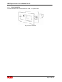
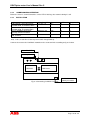
2.2
METER PARTS
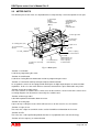
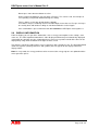
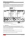
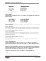
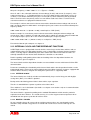
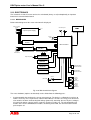
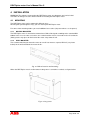
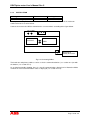
The different parts of the meter are depicted below, accompanied by a short description of each part.
3. Tariff input/
Inputs/
Outputs/
Communication
(Option)
2. Scroll
button
4. Sealable cover
Wiring diagram for:
Tariff input/
Inputs/
Outputs/
Communication
1. Set
5. Meter type label
6. Sealing tape
(on the side)
15. Sealing points (four)
7. Light sensor
14. Communication
window
8. LED
13. LCD
9. Pulse output(s)
or communication
12. Space for ownership
marking
11. Terminal block
and numbering
10. Sealable cover
Wiring diagram for:
Meter connections,
Pulse output(s)/
Communication
Fig. 2-1 Meter parts
-Position 1: Set button
Used when programming the meter.
-Position 2: Scroll-button
Used when viewing different information and when programming the meter.
-Position 3: Terminal for tariff inputs/Inputs/Outputs/Communication
As an option the meter can be equipped with tariff inputs or digital inputs/outputs or communication
capabilities. In this case the meter will have terminals mounted in the place indicated in the picture.
-Position 4 and 10: Sealable covers
The meter contains 2 sealable covers, which cover all the terminals. On the inside of the covers there
are wiring diagrams for all terminals covered by the sealable cover.
-Position 5: Meter type label
Label with important information about the meter.
-Position 6: Sealing tape
A piece of tape sealing the meter, which will leave traces on the meter in case it is broken.
-Position 7: Light sensor
The meter has a light sensor which can be used to view different information in the meter.
-Position 8: LED
The meter has a red Light Emitting Diode that flashes in proportion to the consumed energy.
-Position 9: Pulse output(s) or communication
Page 8 of 137
DELTAplus meter User’s Manual Rev C
Here the meter has terminals for either pulse output(s) or communication (M-bus or LON) purposes.
-Position 10: See position 4.
-Position 11: Terminal block
All the voltages and currents sensed by the meter are connected here.
-Position 12: Space for ownership marking
A small label, marking ownership, can be inserted here.
-Position 13: LCD
A 7-digit Liquid Crystal Display displaying data and settings.
-Position 14 Communication window
For use of external communication devices.
-Position 15: Sealing points
The meter has 2 sealable covers with 2 sealable points on each, where thread seals can be used to
seal the meter (covers all meter connections and the 2 buttons).
2.3
METER TYPES
As mentioned above the DELTAplus meter product family is divided into two groups:
•
•
Direct connected meters for currents 80A
Transformer rated meters (also often called CT-meter) for currents > 80A using external
current transformers (CT’s) with secondary current 6A and optionally external voltage
transformers (VT’s).
Both groups are divided into subgroups:
•
•
•
•
•
•
•
One or three phase connection
Active energy measurement
Combined energy measurement (both active and reactive)
Tariff controlled meters
Meters equipped with communication option
Meters equipped with clock
Meters equipped with inputs and/or outputs
Page 9 of 137
DELTAplus meter User’s Manual Rev C
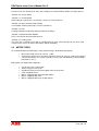
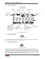
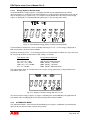
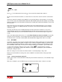
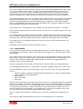
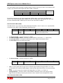
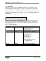
The meter type is reflected on the front label, see figure below.
ABB idnumber
Customization
information
Symbol for
network type
Type designation
Voltage
Frequency
Rated (and maximum) current
and accuracy class
Pulse output frequency
LED frequency
Approval symbols:
Declaration of product
safety, MID, year of
verification,
notified body id
Serial number
Clock
backup time
Protective class II
Year and
week of
manufacture
Operating temperature
range
Fig. 2-2 Meter type label
Note that the nominal voltage spans over a range, 57 to 288 V AC from phase to neutral and 100 to
500 V AC from phase to phase.
A meter is identified with its type designation. For explanation of the positions in the type designation
see further down in this chapter.
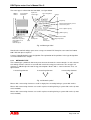
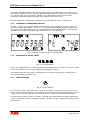
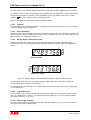
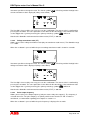
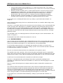
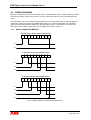
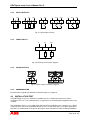
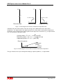
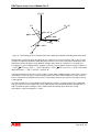
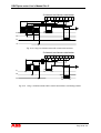
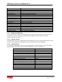
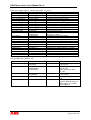
2.3.1
NETWORK TYPE
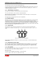
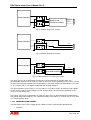
The network type symbol tells how many measurement elements the meter contains. In each element
one voltage and one current is measured and used in the energy measurement. The energy in all
elements is added to give the total energy consumption. Meters with 1, 2 and 3 elements exist, see
figure below.
1 measuring element
2 measuring elements
3 measuring elements
Fig. 2-3 Network symbol
Meters with 1 measuring element are used in single phase metering having a system with 2 wires.
Meters with 2 measuring elements are used in 3-phase metering having a system with 3 wires (2-wattmeter-method).
Meters with 3 measuring elements are used in 3-phase metering having a system with 4 wires (3-wattmeter-method).
Page 10 of 137
DELTAplus meter User’s Manual Rev C
2.3.2
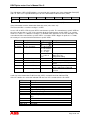
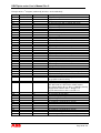
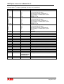
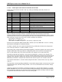
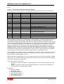
TYPE DESIGNATION
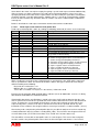
Below are tables with explanation for all positions in the type designation for the meters.
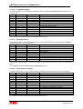
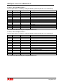
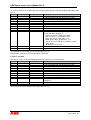
STANDARD METERS WITHOUT COMMUNICATION OPTION
Type
Pos 1 2 3 4 5 6-8
Basic
Standard
Stotz
D
S
Measurement
Active - CTVT connected
Active - direct connected
Combination - CTVT connected
Combination - direct connected
A
B
C
D
Communication
Opto, pulse output
B
Accuracy
Class 1
Class 2
1
2
Voltage
1 x 57-288 V
3 x 100-500 V
3 x 57-288 / 100-500 V
1
2
3
Optional functionality
No options
2 tariffs controlled by 1 input
4 tariffs controlled by 2 inputs
2 tariffs controlled by communication commands
4 tariffs controlled by communication commands
2 tariffs controlled by internal clock or via communication, time dependant functions
4 tariffs controlled by internal clock or via communication, time dependant functions
Time dependant functions
2 tariffs controlled by 1 input, time dependant functions
4 tariffs controlled by 2 inputs, time dependant functions
x00
xx1
xx2
xx3
xx4
xx5
xx6
xx7
xx8
xx9
2 inputs (40V)
2 outputs (230V)
1 in / 1 out (230V)
1 in / 1 out (40V)
2 pulse outputs in combination meters, 1 in all others (230V)
x2x
x4x
x5x
x6x
x7x
Property markings
Verification and inspection
Property markings, verification and inspection
1xx
2xx
3xx
Page 11 of 137
DELTAplus meter User’s Manual Rev C
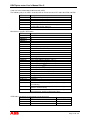
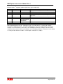
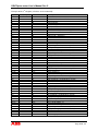
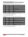
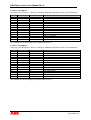
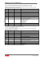
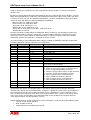
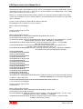
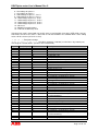
STANDARD METERS WITH M-BUS COMMUNICATION
Type
Pos 1 2 3 4 5 6-8
Basic
Standard
Stotz
D
S
Measurement
Active - CTVT connected
Active - direct connected
Combination - CTVT connected
Combination - direct connected
A
B
C
D
Communication
M-Bus, opto
M
Accuracy
Class 1
Class 2
1
2
Voltage
1 x 57-288 V
3 x 100-500 V
3 x 57-288 / 100-500 V
1
2
3
Optional functionality
No options
2 tariffs controlled by 1 input
4 tariffs controlled by 2 inputs
2 tariffs controlled by communication commands
4 tariffs controlled by communication commands
2 tariffs controlled by internal clock or via communication, time dependant functions
4 tariffs controlled by internal clock or via communication, time dependant functions
Time dependant functions
2 tariffs controlled by 1 input, time dependant functions
4 tariffs controlled by 2 inputs, time dependant functions
x00
xx1
xx2
xx3
xx4
xx5
xx6
xx7
xx8
xx9
2 inputs (40V)
2 outputs (230V)
1 in / 1 out (230V)
1 in / 1 out (40V)
2 pulse outputs in combination meters, 1 in all others (230V)
x2x
x4x
x5x
x6x
x7x
Property markings
Verification and inspection
Property markings, verification and inspection
1xx
2xx
3xx
Page 12 of 137
DELTAplus meter User’s Manual Rev C
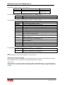
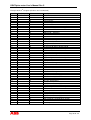
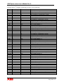
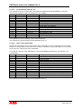
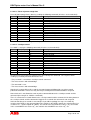
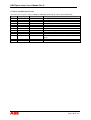
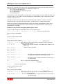
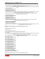
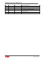
STANDARD METERS WITH LONWORKS COMMUNICATION
Type
Pos 1
2
3
4
5
6-8
Basic
Standard
Stotz
D
S
Measurement
Active - CTVT connected
Active - direct connected
Combination - CTVT connected
Combination - direct connected
A
B
C
D
Communication
LonWorks, opto
L
Accuracy
Class 1
Class 2
1
2
Voltage
1 x 57-288 V
3 x 100-500 V
3 x 57-288 / 100-500 V
1
2
3
Optional functionality
No options
2 tariffs (230V in)
2 tariffs (Com)
4 tariffs (Com)
x00
xx1
xx3
Xx4
1 input (40V)
1 output (230V)
1 pulse output (230V)
x1x
x3x
x7x
Property markings
Verification and inspection
Property markings, verification and inspection
1xx
2xx
3xx
Page 13 of 137
DELTAplus meter User’s Manual Rev C
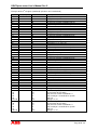
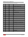
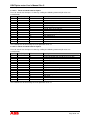
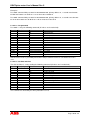
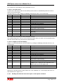
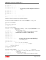
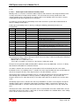
STANDARD METERS WITH EIB COMMUNICATION
Type
Pos 1
2
3
4
5
6-8
Basic
Standard
Stotz
D
S
Measurement
Active - CTVT connected
Active - direct connected
Combination - CTVT connected
Combination - direct connected
A
B
C
D
Communication
EIB, opto, pulse output
E
Accuracy
Class 1
Class 2
1
2
Voltage
1 x 57-288 V
3 x 100-500 V
3 x 57-288 / 100-500 V
1
2
3
Optional functionality
No options
2 tariffs (Com)
4 tariffs (Com)
x00
xx3
xx4
Property markings
Verification and inspection
Property markings, verification and inspection
1xx
2xx
3xx
Page 14 of 137
DELTAplus meter User’s Manual Rev C
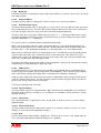
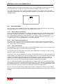
2.4
ENERGY INDICATOR
LED
Fig. 2-4 Energy indicator
The red LED in the middle of the front is an indicator that flashes in proportion to the active energy and
can be used when testing and verifying the meter. Every pulse means that a certain amount of energy
has been registered, that is, it has a certain pulse frequency. This frequency is marked on the
nameplate.
In combined meters (measuring both active and reactive energy) it’s also possible to have the LED
flash in proportion to the reactive energy, see section 2.7.2.9 for more information.
2.5
BUTTONS
The DELTAplus meter has two user buttons behind the sealable cover.
2.5.1.1 SET BUTTON
This is the ”programming” button. It is used to reach Set Mode, activate a change operation and to
confirm a changed setting.
2.5.1.2 SCROLL BUTTON / LIGHT SENSOR
The scroll button and the light sensor lies functionally in parallel, that is pressing the scroll button for a
certain amount of time has the same effect as putting light onto the light sensor for the same amount
of time. The light sensor is placed below the text “SCROLL” and the “torch picture” on the front of the
meter, see picture below. When the meter is sealed only the light sensor can be used. In the text
below only the scroll button is mentioned but everything said is also applicable to the light sensor.
SCROLL
Fig. 2-5 Light sensor
With the scroll button, the information displayed can be changed, such as going to different display
modes or proceeding to the next quantity. No settings can be altered by this button.
The scroll button has two different functions depending for how long time it is pressed:
-Short scroll
When the scroll button is pressed for up to two seconds, it displays the next value. This can
be used if you don’t want to wait for the next quantity to be displayed or you can enter single
step mode to view a value for longer time.
-Long scroll
When the scroll button is pressed for between 2 and 10 seconds it executes an ”Escape”,
see below. When a long scroll is performed in Normal Mode the DELTAplus meter switches
to Alternative Mode. When a long scroll is performed in Alternative Mode the DELTAplus
meter switches to Instrumentation Mode.
Notes:
The activity starts when the button is released.
Page 15 of 137
DELTAplus meter User’s Manual Rev C
Do not press more than one button at a time.
A long scroll in Set Mode lets you step back (”Escape”). This can be used, for example, to
exit a pending set operation without altering the setting.
There is always a ”time out” of two minutes (default).
If a button is not pressed during this time the DELTAplus meter does an ”Escape” and steps
one activity back and continues doing so until Normal Mode is reached again.
If the scroll button is pressed for more than ten seconds the DELTAplus meter ignores it.
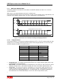
2.6
DISPLAY INFORMATION
From the display you can get all the information, such as energy consumption, active settings, error
status etc. The most important information is either displayed continuously or automatically displayed
sequentially one quantity at a time. Information that is not necessary to be viewed all the time can be
displayed by using either the button or the light sensitive sensor.
The display is two inches wide and has up to 7 characters with a height of 7 mm. The illustration below
shows all segments (forming characters and symbols) that can appear on the display in different
display modes.
Note: In every mode, the energy continues to be measured, the energy registers are updated and the
meter generates pulses.
Page 16 of 137
DELTAplus meter User’s Manual Rev C
2.6.1
DISPLAY OVERVIEW
!
"
!
!
!
"
'
&&
$
&
&& &
$
$
'$
&
(
$
#
%
"
& %
&&
% $
% $
"$
"
Fig. 2-6 DELTAplus meter LCD
2.6.2
VOLTAGE INDICATORS
Fig. 2-7 Voltage indicators
These indicate voltage element presence/absence where a blinking segment means voltage absent
and a segment in a steady on state means voltage present.
2.6.3
OK AND ERROR SYMBOLS
Fig. 2-8 Status symbols
The OK and Error segments constantly indicate the overall status of the meter. Only one of the
segments is lit at a time. Besides indicating the status of the meter itself, they are also used to indicate
the result of an installation check, which is a function where the meter itself every second checks the
installation. If the result of the installation check detected no errors and no meter errors are pending
the OK symbol is on. If an installation error was detected or a meter error is pending the Error symbol
is on. The error segment will be kept on as long as any error is pending.
Page 17 of 137
DELTAplus meter User’s Manual Rev C
Information regarding pending errors can be viewed in alternative mode where each error have an
error code. Installation errors lies between 100-128 and date and time error have error code 140 and
141. Internal meter errors lies between 200-201. If any of the internal errors occur the meter
functionality cannot be guaranteed and the meter shall be taken out of service.
For more information regarding the installation check and installation errors see chapter 4.3.
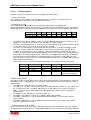
2.6.4
7-SEGMENT 7 CHARACTERS AND UNIT
All values, such as energy, power, voltage and current etc, are displayed by using the 7-segment 7
characters and the unit segments. There are also 2 decimal points to enable display of values with 1
or 2 decimals. The figure below shows an example where the active energy without a decimals with
unit kWh and the reactive total power with 1 decimal and unit var is displayed.
Fig. 2-9 Display of active energy and reactive power
2.6.5
INDICATION OF ACTIVE TARIFF
Fig. 2-10 Tariff indicators
Active tariff is indicated with a constant flashing of the tariff indicator for example ”T1” for tariff 1. When
a value for a tariff which is not active is displayed its indicator remains lit.
The only time when the active tariff is not blinking is when a total energy register is displayed or an
LCD test is pending (all segments on).
2.6.6
LOAD INDICATOR
Fig. 2-11 Load indicator
There are three arrows, which will rotate as soon as the current is above the start current level in at
least one of the measuring elements. The rotating speed is constant and independent of the measured
energy. If the metering is below the start current level all the arrows are constant and not rotating.
If the total active energy is positive the arrows is rotating in the forward direction and if the total active
energy is negative the arrows is rotating backwards. If the total energy is negative the energy registers
will stand still.
Page 18 of 137
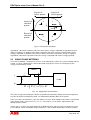
DELTAplus meter User’s Manual Rev C
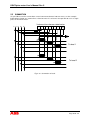
2.7
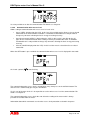
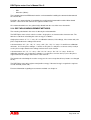
DISPLAY MODES
The DELTAplus meter display system is divided into different display modes: Normal, Alternative and
Instrumentation Mode. They are distinguished from each other by the small triangle at the bottom
middle of the LCD which is off in Normal Mode, continuously on in Alternative Mode and flashing in
Instrumentation Mode. There is also a Set Mode where different programmable settings can be
modified. Some information are always displayed on the LCD, irrespective of active mode. Below in
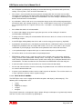
the figure are depicted the display system with its different modes and the different information
displayed.
Always displayed
•Connected phases
•Load indication
•CT/VT ratio used indication
•Active tariff (not at total energy display)
•Error status
Normal mode
Alternative mode
•Total active energy and per tariff
•Total reactive energy and per tariff
LSc
•LCD test
•Error codes
•Active energy consumption/tariff
•Reactive energy consumption/tariff
•Total active and reactive consumption
•Date and time
•Total transformer ratio
•Voltage transformer ratio
•Current transformer ratio
•Input counter 1, counter 2
•Input status 1, 2
•Input stored status 1, 2
•Pulse output frequency
•Primary address
•Baudrate
•Communication status
•LED reactive
•Write protection level
S
Instrumentation mode
•Active power for each element3
•Total active power
•Reactive power for each element
•Total reactive power
•Total apparent power
•Voltage and current for each element
•Total power factor
•Active quadrant
•Frequency
•Current harmonics
LSc
S
LSc
S
Set mode
LSc
LSc
Ct xxxx
S
Set CT ratio
Sc
Ut xxxx
LSc
Sc
S
Set VT ratio
P xxxx
Bd xxxx
S
Set Pulse
frequency
LSc
LSc
Sc
Sc
S
Set M-bus
baud rate
Adr xxx
LSc
Sc
dDDMMYY
S
Set M-bus
address
S
Set Date
S = Set button press
Sc = short press on Scroll button
LSc = Long Scroll (Scroll button pressed 2 sec or more)
When LSc is used in a set operation it acts like an escape, that is,
it goes out of the active set operation and no change is performed.
LSc
LSc
Sc
hh_mm.ss
Sc
OPEn
S
S
Set Time
Sc
Set Write
access level
= VT/CT connected only
= optional
Items with italic font are optional
Fig. 2-12 Display system
2.7.1
NORMAL MODE
Normal Mode is the ”normal” display condition where the most important quantities, normally the
energies which are used for billing, are displayed sequentially and automatically one at a time.
Normally each quantity is being displayed for 6 seconds. When the last quantity has been displayed it
will start all over again displaying the first quantity. If the “scroll” button is pressed shortly it’s possible
to single step and view a quantity for longer time.
All meters will be in Normal Mode after power up.
Normal mode will always be reached after some time if no buttons are pressed as the meter
automatically steps back until it reaches Normal Mode.
The Normal Mode can only be interrupted by entering the Set Mode or the Alternative Mode.
Below is described the format for the energy display in Normal Mode.
Page 19 of 137
DELTAplus meter User’s Manual Rev C
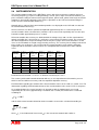
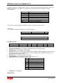
2.7.1.1 Energy display in Normal mode
In Normal Mode the energy registers are displayed in kWh (kvarh) without decimals in direct
connected meters. In tariff meters the tariff indicators are used to indicate which tariff energy register
that are displayed (see section 2.6.5), see example in figure below where the tariff 2 active energy
register is displayed (T1 is blinking indicating that tariff 1 is the currently active tariff).
Fig. 2-13 Normal Mode energy display in direct connected meter
In all transformer rated meters set to secondary metering (CT = VT = 1) the energy is displayed in
kWh (kvarh) with 1 decimal in Normal Mode.
At primary metering (CT*VT > 1) the displayed values in Normal mode is shifted ”one step” to the left
for every factor of 10 in the transformer ratio settings, see below:
Transformer ratio
CT x VT < 10:
10 < CT x VT < 100:
100 < CT x VT < 1000:
1000 < CT x VT < 10 000:
CT x VT >10 000 :
Energy format displayed
kWh (kvarh),1 decimal
kWh (kvarh), without decimal
MWh (Mvarh), 2 decimals
MWh (Mvarh), 1 decimal
MWh (Mvarh), without decimal
The figure below shows an example where the reactive energy (unit kvarh) is displayed when the
transformer ratio is 50.
Fig. 2-14 Display of reactive energy with CT*VT = 50
The internal meter energy registers are kept in secondary form and multiplied by the programmed
transformer ratios and displayed on the LCD in primary form in Normal mode.
2.7.2
ALTERNATIVE MODE
The Alternative Mode is reached from Normal Mode by pressing the scroll button (or activating the
light sensor) for more than two seconds (“long scroll”).
Page 20 of 137
DELTAplus meter User’s Manual Rev C
The DELTAplus meter indicates being in Alternative mode by the triangle (
) being permanently lit:
If no button is pressed after entering Alternative mode the different display items will be automaticaly
displayed one at a time in sequence. If the scroll button is pressed shortly it single steps (”hand”
symbol
on) and each item can be viewed longer time.
Below is described the information shown in Alternative Mode.
2.7.2.1 LCD test
The first display item in Alternative Mode is a display test where all LCD segments are set (see figure
2.6 which displays all LCD segments):
2.7.2.2 Error information
After the LCD test the installation check errors and internal meter errors are displayed. If no errors are
detected the text “no Err” is displayed. The error codes are displayed as “Err xxx” (error code xxx). The
different errors are explained in chapter 4.3.3.
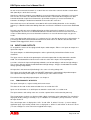
2.7.2.3 Energy display in Alternative mode
In Alternative mode the energy registers are displayed in kWh (kvarh) with 1 decimal in direct
connected meters, see figure below which illustrate the difference between Normal and Alternative
mode.
Normal mode
Alternative mode
Fig. 2-15 Energy display in Normal/Alternative Mode in direct connected meters
In transformer rated meters the secondary energy in kWh (kvarh) with 2 decimals is displayed
(irrespective of the transformer ratio settings).
In tariff meters the tariff indicators are used to indicate which tariff energy register that are displayed
(see section 2.6.5)
2.7.2.4 Transformer ratio
The transformer ratio settings is displayed (in transformer rated meters). The total transformer ratio
(CT*VT) is displayed as “t xxxxxx”, the current transformer ratio (CT) as “Ct xxxx” and the voltage
transformer ratio (VT) as “Ut xxxx”.
2.7.2.5 Pulse output frequency
The pulse output frequency is displayed (in meters with pulse output(s)) as “P xxxxx” where xxxxx is
the frequency in impulses/kWh (kvarh).
Page 21 of 137
DELTAplus meter User’s Manual Rev C
2.7.2.6 Baud rate
The M-bus baud rate is displayed (in meters with electrical M-bus) as “bd xxxx” where xxxx is the baud
rate in bits/seconds.
2.7.2.7 Primary address
The M-bus primary address is displayed as “Adr xxx” where xxx is the primary address.
2.7.2.8 Communication status
The M-bus communication status is displayed as “C-xxxxx” where xxxxx are different codes that reflect
what’s happening on the bus. In meters with electrical M-bus it displays the status of the electrical Mbus and in all other meters the status of the the infrared (IR) communication port.
As long as there are no messages addressed to the meter “C------” is displayed. Note that messages
on the bus with different baud rate than the meter baud rate or messages addressed to other meters
will not be displayed (“C------” displayed).
This can be used as an aid when trouble-shooting communication.
When a message addressed to the meter is detected it displays “C-A x” while communicating. The
letter A stands for that the meter is addressed and x denotes different internal communication states.
Possible states: 1 : Idle (waiting for command), 2-3 : Receiving states, 4-7 : Transmitting states.
When errors are detected “C-Erxxx” is displayed where xxx is a number that varies depending on the
error. Possible error codes: 301 : Checksum error in received message, 302 : Write access not
allowed, 303 : Syntax error (protocol error in received message), 304 : Uart error (for example parity
error), 305 : Timeout error, 306 : Wrong password.
This display item will be displayed for 4 hours if the scroll button is not pressed (short or long scroll) or
until power off. It is displayed only in single step mode.
2.7.2.9 LED reactive
On combined meters it is possible to have the red LED energy indicator to flash in proportion to the
reactive energy instead of the active energy (which it normally does). This is done by single stepping
to the “LED reactive” display item. When this is reached the text “LEd rEA” is displayed.
It will stay in this mode until: 4 hours have passed if the scroll button is not pressed (by short or long
scroll) or a power outage occurs. The pulse frequency for the reactive energy flashing is the same as
for the active energy (marked on the nameplate).
This item is not displayed in auto scroll.
2.7.2.10 Input counter(s)
The input counter registers are displayed with 7 digits (maximum value 9 999 999). The unit which is
displayed (factory setting) is normally ”r” (as in ”rotations” or ”revolutions”) for input counter 1 and ”rh”
for input counter 2.
2.7.2.11 Input status
The current input status is displayed as ”InP1 X” and ”InP2 X” where X is 0 or 1 (1 means voltage
applied to input).
2.7.2.12 Input stored status
The input activity stored status is displayed as ”InPA1 X” and ”InPA2 X” where X is 0 or 1 (1 means
voltage has at least once been applied to the input ).
2.7.2.13 Date
In meters with internal clock the date is displayed as ”dxxxxxx” where xxxxxx is day, month and year.
The 13:th of may 2007 will for example be displayed as ”d130507”.
Page 22 of 137
DELTAplus meter User’s Manual Rev C
If the date is not set ”d------” is displayed.
2.7.2.14 Time
In meters with internal clock the time is displayed as ”xx_xx.xx” where xx_xx.xx is hours, minutes and
seconds. The time 23:37:58 will for example be displayed as ”23_37.58”.
If the time is not set ”--_--.--” is displayed.
2.7.2.15 Write protection level
The active write protection level is displayed. In meters with internal clock some of the programmable
parameters for the time dependant function can be write protected. 3 different protection levels exist:
Open for write accesses (“Open” displayed), open by password for write accesses (“Open P”
displayed) and closed for write accesses (“CLoSEd” displayed).
2.7.3
INSTRUMENTATION MODE
In this mode it is possible to see additional information about the connected currents and voltages.
The Instrumentation Mode is reached from Alternative Mode by pressing the scroll button (or activating
the light sensor) for more than two seconds (“long scroll”).
The DELTAplus meter indicates being in this mode by flashing the triangle (
).
If no button is pressed after entering Instrumentation mode the different display items will be
automaticaly displayed one at a time in sequence. If the scroll button is pressed shortly it single steps
(”hand” symbol
on) and each item can be viewed longer time.
The instrumentation quantities are displayed in primary form, that is, the measured secondary values
are multiplied by the transformer ratios when displayed on the LCD.
A long scroll will take the meter back to Normal mode.
Below is described the information shown in Instrumentation Mode.
2.7.3.1 Power
The format of the power displayed depends on the magnitude. The table below shows the format for
different magnitudes.
Power (kW/kvar/kVA)
P<1:
1 < P < 10 :
10 < P < 100 :
100 < P < 1000 :
1000 < P < 10 000 :
10 000 < P < 100 000 :
100 000 < P < 1 000 000 :
Power format displayed
W/var/VA, no decimal
kW/kvar/kVA with 2 decimals
kW/kvar/kVA with 1 decimal
kW/kvar/kVA, no decimal
MW/Mvar/MVA with 2 decimals
MW/Mvar/MVA with 1 decimal
MW/Mvar/MVA, no decimal
The per element and total active power are displayed on all meters. In combined meters also the per
element and total reactive power and total apparent power are displayed.
The power is presented in the format “Px XXXX unit” where x is the element number (1-3) or “t” for the
total power (for example “P2 2293 var” for the element 2 reactive power or “Pt 15.78 kVa” for the total
apparent power).
2.7.3.2 Voltage
The format of the voltage displayed depends on the magnitude. The table below shows the format for
different magnitudes.
Page 23 of 137
DELTAplus meter User’s Manual Rev C
Voltage (kV)
U<1:
1 < U < 10 :
10 < U < 100 :
100 < U < 1000 :
U ≥ 1000 :
Voltage format displayed
Volt with 1 decimal
Volt, no decimal
kV with 2 decimals
kV with 1 decimal
kV, no decimal
The voltage is displayed for each element in the format “Ux XXX.X unit” with x being the element
number (for example “U1 230.4 V”).
2.7.3.3 Current
The format of the current displayed depends on the magnitude. The table below shows the format for
different magnitudes.
Current (Amperes)
I < 100 :
100 < I < 1000 :
1000 < I < 10 000 :
1000 < I < 10 000 :
I ≥ 10 000 :
Current format displayed
Amperes with 2 decimals
Amperes with 1 decimal
Amperes, no decimal
Amperes, no decimal
kA with 2 decimals
The current is displayed in the format “Ax XX.XX unit” (for example “A3 22.93 a” for a current of 22.93
Amperes on phase 3).
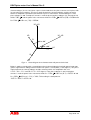
2.7.3.4 Power factor
Power factor is displayed with 2 decimals in the format “Pfx X.XX” where x is the element number (13) or “t” for the total power (for example Pft 0.44). Normally only the total power factor is displayed.
For definition of the different quadrants see section 5.1.
2.7.3.5 Active quadrant
In combined meters the total active quadrant is displayed in the format “Lt X” where X is the active
quadrant number 0-4, for example “Lt 1” if the total load is in quadrant 1 (inductive load). Zero is
presented if the load is zero.
For definition of the different quadrants see section 5.1.
2.7.3.6 Frequency
The frequency is measured in hertz with 2 decimals and displayed in the format “Fr XX.XX” (for
example Fr 50.03).
2.7.3.7 Current harmonics
The total current harmonic distorsion of the harmonics measured is displayed in percent with 1
decimal in the format “dx XXX.X” where x is the phase number (1-3). 999.9 % will be displayed if the
harmonic is bigger than 999.9 %. The separate harmonics is displayed in percent with 1 decimal in the
format “dxy XX.X” where x is the phase number (1-3) and y is the harmonic number (2-9). 99.9 % will
be displayed if the harmonic is bigger than 99.9 %. The separate harmonic frequencies measured is
multiples of the fundamental frequency (normally around 50 or 60 Hz) up to the 9:th harmonic but not
higher than 500 Hz. At 60 Hz for example the 9:th harmonic will have frequency 540 Hz and will then
not be measured. If the harmonic have not been measured “dxy --.-” is displayed.
The current harmonics (2-9) together with the fundamantal is measured sequentially one at a time
(approximately 1 harmonic each second). Each harmonic is calculated according to:
I /I
n
f
• 100%
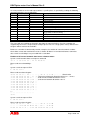
and the total current harmonic distorsion for the harmonics measured is calculated according to:
Page 24 of 137
DELTAplus meter User’s Manual Rev C
9
n=2
where
2
I /I
n
I
f
f
• 100%
is the fundamental current and
I
n
is the current for harmonic with number n.
At each measurement the harmonic is set to 0 if the rms value of the current is below a certain lower
limit.
Note that as only the harmonics up to 500 Hz is measured and because the harmonics is measured
one at a time is not a true total harmonic distorsion which would require that all harmonics up to infinite
frequency would be measured and that all harmonics including the fundamental would be measured at
the same time.
Note also that presence of harmonics over 500 Hz will result in folding distorsion as the sampling
frequency is 1000 Hz. The folding distorsion can affect the measurements below 500 Hz and give
erroneous results.
Due to the possible presence of folding distorsion and the fact that the harmonics is measured
sequentially one at a time it is recommended that the harmonic measurement results of the meter is
used as a tool to detect presence of harmonics and not as an exact instrument to get very precise
results.
In the event log function of the meter (see section Error! Reference source not found.) it is possible
to log presence of harmonics. A percentage limit for the total harmonic distorsion of the harmonics
measured is then set and the start time/date and duration will be logged if this limit is exceeded.
2.7.4
SET MODE
Set mode is reached by pressing the Set button while being in Normal, Alternative or Instrumentation
mode. For a flowchart on Set mode see figure 2-12 in section 2.7 (optional settings are in italic style).
After reaching Set mode the different set items and its respective setting can be viewed by pressing
the scroll button (short scroll). To activate the change procedure the set button is pressed when the
set item to be changed are displayed. The ”hand” symbol (
) is flashing while the change
procedure is active. Doing a “long scroll” while the set operation is pending lets you to exit without
altering the setting (”Escape”).
When all settings have been done the Normal mode is reached by doing a “long scroll”.
Below are listed the different settings that can be modfied in Set mode and the change operation
procedure.
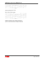
2.7.4.1 Current transformer ratio (CT)
Allows you to set the current transformer ratio (only on transformer rated meters). The allowable range
is 1 – 9999.
When the set button is pressed while the present current transformer ratio is shown in set mode
Page 25 of 137
DELTAplus meter User’s Manual Rev C
it becomes possible to change the ratio. The ”hand” symbol (
current transformer ratio is displayed (always starts with 0)
) is flashing and the first digit in the
The first digit is increased by 1 for every press on the scroll button. The chosen value is confirmed by
pressing the set button. The same procedure is then done for the other digits. If the transformer ratio
set was bigger than 1 (primary metering) the ”primary metering” symbol (
) will be on.
Note that the allowable maximum total transformer ratio (CT*VT) is 999 999.
2.7.4.2 Voltage transformer ratio (VT)
Allows you to set the voltage transformer ratio (only on transformer rated meters). The allowable range
is 1 – 9999.
When the set button is pressed while the present voltage transformer ratio is shown in set mode
it becomes possible to change the ratio. The ”hand” symbol (
voltage transformer ratio is displayed (always starts with 0)
) is flashing and the first digit in the
The first digit is increased by 1 for every press on the scroll button. The chosen value is confirmed by
pressing the set button. The same procedure is then done for the other digits. If the transformer ratio
set was bigger than 1 (primary metering) the ”primary metering” symbol (
) will be on.
Note that the allowable maximum total transformer ratio (CT*VT) is 999 999.
2.7.4.3 Pulse output frequency
Allows you to set the pulse output frequency (only on meters with pulse output(s)). The frequency is
selected from a list. The pulse output(s) are primary which means that the CT and VT ratio are
considered, see information regarding pulse outputs in section 2.11.
When the set button is pressed while the pulse frequency is displayed in set mode
Page 26 of 137
DELTAplus meter User’s Manual Rev C
the ”hand symbol (
) will flash, and you can go through all values with the scroll button (short
scroll) and select the preferred value with the set button.
2.7.4.4 Reset of energy registers
Allows you to reset energy registers. This is an option and is normally present only in some “special
meters”.
When the set button is pressed while “rESEt” is displayed in set mode
) will start flashing. If then the set button is pressed all registers except the total are
the hand (
set to zero (both active and reactive).
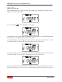
2.7.4.5 Primary address
Allows you set the M-bus primary address.
When the set button is pressed while the primary address is displayed in set mode
Page 27 of 137
DELTAplus meter User’s Manual Rev C
the ”hand” symbol (
with 0)
) starts flashing and the first digit in the address is displayed (always starts
The first digit is increased by 1 for every short press on the scroll button. The chosen value is
confirmed by pressing the set button. The same procedure is then done for the 10-digit and finally the
100-digit. When the 100-digit is confirmed and the meter will start to use the new address. It is only
possible to select valid addresses (0-250). A selected primary address can be used both for the optical
port and the electrical M-bus (if present).
2.7.4.6 Baud rate
Allows you set the M-bus electrical bus baud rate (only in meters with electrical M-bus).
When the set button is pressed while the baud rate is displayed in set mode
the ”hand” symbol (
) begins flashing, and you can now go through all 6 values (300 – 9600 baud)
with the short scroll button, and select the preferred value with the set button.
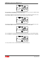
2.7.4.7 Time
Allows setting of the time.
When the SET button is pressed while the time (hour, minute, second) is displayed in Set mode
the ”hand” symbol (
) and the hour digits starts flashing
Page 28 of 137
DELTAplus meter User’s Manual Rev C
The hour digits are increased by 1 for every short press (possible values 0-23) on the SCROLL button.
The chosen value is confirmed by pressing the SET button.
The minute tens digit then starts flashing and is increased for every short press (possible values 0-5)
on the SCROLL button. The chosen value is confirmed by pressing the SET button.
The minute unit digit then starts flashing and is increased for every short press (possible values 0-9)
on the SCROLL button. The chosen value is confirmed by pressing the SET button.
The second digits then starts flashing and is set to zero at every short press on the SCROLL button.
The second digits are confirmed by pressing the SET button which completes the time set operation.
It is also possible to set time via communication. For details see chapter 6.
Page 29 of 137
DELTAplus meter User’s Manual Rev C
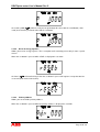
2.7.4.8 Date
Allows setting of the date.
When the SET button is pressed while the date (day:month:year) is displayed in Set mode (13:th of
august year 2007 in figure below)
the ”hand” symbol (
) and the day digits starts flashing
The day digits are increased by 1 for every short press (possible values 1-31) on the SCROLL button.
The chosen value is confirmed by pressing the SET button.
The month digits then starts flashing and is increased for every short press (possible values 1-12) on
the SCROLL button. The chosen value is confirmed by pressing the SET button.
The year tens digit then starts flashing and is increased for every short press (possible values 0-9) on
the SCROLL button. The chosen value is confirmed by pressing the SET button.
The year unit digit then starts flashing and is increased at every short press (possible values 0-9) on
the SCROLL button. When the chosen value is confirmed by pressing the SET button the new date is
set.
Page 30 of 137
DELTAplus meter User’s Manual Rev C
It is also possible to set date via communication. For details see chapter 6.
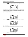
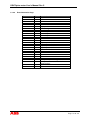
2.7.4.9 Communication write access level
Allows setting of communication write access level. 3 levels exist:
•
Open (“OPEn” displayed on the LCD). In this level it is possible to give all types of user related
commands to the meter without restrictions. It should be mentioned that it is not possible to
change any constants affecting the basic energy measuring accuracy.
•
Open by password (“OPEn P” displayed on the LCD): In this level it is possible to give all
types of user related commands after sending a correct password to the meter. It should be
mentioned that it is not possible to change any constants affecting the basic energy measuring
accuracy.
•
Closed (“CloSEd” displayed on the LCD): In this level the meter is closed for all user related
commands.
When the SET button is pressed while the communication write access level is displayed in Set mode
the ”hand” symbol (
) starts flashing
The communication write access level is changed for every short press on the SCROLL button. The
chosen level is confirmed by pressing the SET button.
If it is in any of the open levels it is also possible to set the write access level via communication. For
details see chapter 6.
The communication write access level does not affect the reading of the meter and it is always
possible to read data from the meter.
Information about which commands use the write access level protection are found in chapter 6.
Page 31 of 137
DELTAplus meter User’s Manual Rev C
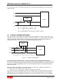
2.8
INSTRUMENTATION
The instrumentation functions in the DELTAplus meter, with all measurements enabled, consist of
measuring frequency, per phase reading of voltage, current, phase angle and current harmonics, per
phase and total reading of active/reactive/apparent power, power factor, power factor angle and active
quadrant. It also includes displaying some of these quantities on the LCD and communicating the
results over the communication interface(s).
Normally only a subset of the instrumentation quantities are displayed on the LCD and sent out over
the communication interface(s).
All measurements are done in parallell and updated approximately once a second except for the
current harmonics where the harmonics (numbers 2-9) are measured sequentially one at a time (one
harmonic number approximately once a second).
All instrumentation data accuracy are defined within the voltage range ±20 % of the stated nominal
voltage and within the current range 5 % of the base current to the maximum current. The accuracy of
all instrumentation data except the voltage and current phase-angles and current harmonics are the
same as the IEC 62053-21 stated energy metering accuracy. The accuracy for the voltage and current
phase-angles are ±2 degrees. The accuracy for the current harmonics varies with the harmonic
amplitude and the harmonic number and are are valid provided that no harmonics above 500 Hz
exists:
Harmonic
number
1%<
distorsion
<5%
± 0.5 %
± 0.7 %
± 1.0 %
± 1.2 %
± 1.5 %
± 1.7 %
± 2.0 %
± 2.5 %
2
3
4
5
6
7
8
9
5%<
distorsion
< 10 %
± 1.0 %
± 1.5 %
± 2.0 %
± 2.5 %
± 3.0 %
± 3.5 %
± 4.0 %
± 5.0 %
10 % <
distorsion
< 20 %
±2%
±3%
±4%
±5%
±6%
±7%
±8%
± 10 %
20 % <
distorsion
< 50 %
±4%
±6%
±8%
± 10 %
± 12 %
± 14 %
± 16 %
± 20 %
50 % <
distorsion
< 100 %
±2%
±3%
±4%
±5%
±6%
±7%
±8%
± 10 %
For distorsion levels below 1 % there’s an absolute uncertainty of ± 0.5 %.
The accuracy of the total harmonic distorsion will vary as it is dependant on all harmonics present
which in turn have different accuracy and also amplitude depndant accuracy.
For information regarding presentation of the instrumentation values on the LCD see section 2.7.3. For
information regarding communication formats of the instrumentation values on the LCD see chapter 6.
As mentioned above the current harmonics (2-9) together with the fundamantal is measured
sequentially one at a time (approximately 1 harmonic each second). Each harmonic is calculated
according to:
I /I
n
f
• 100%
and the total current harmonic distorsion for the harmonics measured is calculated according to:
9
n =2
where
2
I /I
n
I
f
f
• 100%
is the fundamental current and
I
n
is the current for harmonic with number n.
Page 32 of 137
DELTAplus meter User’s Manual Rev C
At each measurement the harmonic is set to 0 if the rms value of the current is below a certain lower
limit (normally 5% of the basic current).
Note that as only the harmonics up to 500 Hz is measured, and because the harmonics is measured
one at a time, it is not the true total harmonic distorsion that is calculated. Measuring the true total
harmonic distorsion require that all harmonics up to infinite frequency is measured and that all
harmonics including the fundamental would be measured at the same time.
Note also that presence of harmonics over 500 Hz will result in folding distorsion as the sampling
frequency is 1000 Hz and that the folding distorsion can affect the harmonic measurements below 500
Hz.
Due to the possible presence of folding distorsion and the fact that the harmonics is measured
sequentially one at a time it is recommended that the harmonic measurement results of the meter is
used as a tool to detect presence of harmonics and not as an exact instrument to get very precise
results.
In the event log function of the meter (see section 2.12.5) it is possible to log presence of harmonics. A
percentage limit for the total harmonic distorsion measured is then set and the start time/date and
duration will be logged if this limit is exceeded.
2.9
INPUTS AND OUTPUTS
As an option the meter can be equipped with inputs and/or outputs: Either 1 or 2 inputs or outputs or 1
input and 1 output.
The inputs/outputs are built with optocouplers and are galvanically isolated from all other meter
electronics.
The inputs consists beside of the optocouplers of interface/protection circuitry towards the outside
world. The microcontroller inside the meter reads the status of the inputs via the optocouplers.
2 versions exist for the input and input/output boards, one for low voltages and one for high voltages.
The versions with only outputs handle both low and high voltages. All types handle both DC and AC
voltage (polarity independent).
An input that is not connected (left floating) is the same as having voltage "off".
The outputs are built with with solid state MOSFET-optocouplers with polarity independent outputs.
The equivalent circuitry of the outputs is an ideal relay in series with a resistor.
For technical data regarding inputs/outputs see chapter 3.
2.9.1
FUNCTIONALITY OF INPUTS
The inputs count pulses, register activity and current status.
This data can be read via the communications bus or read on the LCD.
Inputs can also function as as tariff inputs to control the active tariff, see section 2.10.
The input counters and activity status are saved at a power failure and restored at power up.
The 2 input counter registers are displayed with 7 digits (maximum value 9 999 999). The unit which is
displayed (factory setting) is normally ”r” (as in ”rotations” or ”revolutions”) for input counter 1 and ”rh”
for input counter 2.
The current input status is displayed as ”InP1 X” and ”InP2 X” where X is 0 or 1 (1 means voltage
applied to input). Input activity stored status is displayed as ”InPA1 X” and ”InPA2 X” where X is 0 or 1
(1 means voltage has at least once been applied to the input ).
Page 33 of 137
DELTAplus meter User’s Manual Rev C
The stored status can be reset via the communications bus.
On meters with internal clock and inputs the following additional functions for the inputs can be used:
Load profile, monthly values and maximum demand. For information regarding these functions see
sections describing these functions.
2.9.2
FUNCTIONALITY OF OUTPUTS
The outputs are controlled via communication or via the internal clock.
The status of the outputs can be read via the communication bus.
When the outputs are controlled via communication the status of the outputs is saved at a power
failure and restored at power up.
The output relays are always open if the meter is not powered.
2.10 TARIFF INPUTS
DELTAplus meters with tariff functionality (option) have the tariffs controlled either via communication,
the internal clock or by 1 or 2 tariff inputs. Tariff control via inputs are done by applying a proper
combination of "voltage" or "no voltage" to the input(s). Each combination of "voltage"/"no voltage" will
result in that the meter will register the energy in a particular tariff register. In combined meters with
both active and reactive metering both quantities are controlled by the same inputs and the active tariff
for the active and reactive energy will always be the same.
2.10.1 CONNECTIONS
The tariff inputs consist of 2 inputs numbered 15 (TIN1) and 16 (TIN2) and a 3:rd common input
numbered 13, see below. For 2-tariff meters TIN1 is used. For 4-tariff meters both TIN2 and TIN1 are
used.
C
TIN1
TIN2
13
15
16
Fig. 2-16 Tariff input connection diagram
For more data regarding the tariff inputs see section 2.9 and section 3.3.1 (technical data for high
voltage inputs).
2.10.2 INDICATION OF ACTIVE TARIFF
The active tariff is reflected on the LCD by blinking with one of the 4 segments "T1", "T2", "T3" and
"T4". "T1" blinks if tariff 1 is active, "T2" if tariff 2 is active etc. The active tariff segment will always
blink except when the total active or reactive energy is displayed where all "Tx" segments are off.
2.10.3 INPUT CODING
The normal coding of the inputs is binary as described below. Reservations should be made however
for "special meters" where different coding is required.
Meter with 4 tariffs:
The inputs have the following "input voltage -> active tariff" table:
TIN1/TIN2 = off/off -> Tariff 1 active ("T1" blinks on the LCD)
Page 34 of 137
DELTAplus meter User’s Manual Rev C
TIN1/TIN2 = on/off -> Tariff 2 active ("T2" blinks on the LCD)
TIN1/TIN2 = off/on -> Tariff 3 active ("T3" blinks on the LCD)
TIN1/TIN2 = on/on -> Tariff 4 active ("T4" blinks on the LCD)
Meter with 2 tariffs:
TIN1/TIN2 = off/off -> Tariff 1 active
TIN1/TIN2 = on/off -> Tariff 2 active
TIN1/TIN2 = off/on -> Tariff 2 active
TIN1/TIN2 = on/on -> Tariff 2 active
Note: With the above coding it'
s enough to use only one input (TIN1 or TIN2), the other input can be left
floating.
2.11 PULSE OUTPUTS
The DELTAplus meter is normally equipped with one pulse output for active energy, with terminals
numbered 20 and 21. The meter sends out a certain amount of pulses per kilowatt hour.
Combined meters (measure both active and reactive energy) normally have 2 pulse outputs, one for
the active and one for the reactive energy, with terminals numbered 20, 21 and 22. 21 is the common
terminal, 20 the active and 22 the reactive terminal.
The pulse outputs are primary, which means that the pulses are sent out in proportion to the true
primary energy. For transformer rated meters this is done by using the current and voltage transformer
ratios (CT and VT ratio) programmed into the meter. For direct connected meters there are no external
transformers used and the amount of pulses sent out are in proportion to the energy flowed through
the meter.
The pulse outputs are galvanically isolated from the rest of the electronics in the meter.
They fulfil and supersede the German DIN 43 864 standard (often called S0) and the IEC standard
62053-31.
The outputs have a maximum voltage and current specified to 247 Volt AC, 350 V DC 100 mA. They
are built with MOSFET-optocouplers with polarity independent outputs. The equivalent circuitry of the
outputs is depicted below and consists of an ideal relay and a series resistor of typically 20 Ω.
kvarh
kWh
20Ω
20
21
kWh
20Ω
20Ω
22
21
20
Fig. 2-17 Pulse output equivalent schematic diagram
2.11.1 PULSE FREQUENCY AND PULSE LENGTH
The pulse frequency is programmable (marked on the nameplate) with the pulse frequency selected
from a list using the buttons. The pulse length is fixed and is normally set to 100 ms. Regarding the
choice of pulse frequency, it should be noted that there is a risk that the pulses may go into each other
if the power is too high. In this case the meter may send out a new pulse (closes the relay) before the
previous pulse has been terminated (relay opened) and the pulse will be missed. The worst case
scenario is that the relay can be closed all the time. To avoid this problem a calculation should be
made to work out the maximum pulse frequency allowed at a particular site based upon an estimated
maximum power and the meter pulse output data.
The formula to use when doing this calculation is:
Page 35 of 137
DELTAplus meter User’s Manual Rev C
Max pulse frequency = 1000 * 3600 / U / I / n / (Ppause + Pwidth)
where U and I is the estimated maximum element voltage (in volts) and current (in amperes), n the
number of elements (1 - 3), Pwidth and Ppause is the pulse width and the required pulse pause (in
seconds). A reasonable minimum pulse pause is 0.03 (30 ms) which conforms to the S0 standard.
Note U and I have to be the primary values in a transformer rated meter if the CT and VT for the
external transformers are programmed into the meter.
For example in a direct connected 3-element meter with estimated maximum voltage and current of
250 V and 65 A and pulse width 100 ms and required pulse pause 30 ms the maximum allowed pulse
frequency will be:
1000 * 3600 / 250 / 65 / 3 / (0.030 + 0.100)) = 568 impulses / kWh (kvarh)
Another example: In a transformer rated 3-element meter with estimated maximum voltage and
current of 63 * 100 V = 6300 V (VT ratio 100) and 6 * 50 A = 300 A (CT ratio 50) and pulse width 100
ms and required pulse pause 30 ms the maximum allowed pulse frequency will be:
1000 * 3600 / 6300 / 300 / 3 / (0.030 + 0.100) = 6.16 impulses / kWh (kvarh)
For technical data on pulse outputs see chapter 3.
2.12 INTERNAL CLOCK AND TIME DEPENDANT FUNCTIONS
In DELTAplus meters equipped with internal clock the meter keeps track of date and time and are
equipped with various time dependant functions such as load profile, maximum demand, monthly
values, event log, outputs controlled by time and in tariff meters with internal clock the tariffs are
normally controlled via the internal clock. Below these functions are described.
Details regarding reading/writing of time/date and reading of the time dependant functions via
communication is given in chapter 6.
The internal clock and time dependant functions are not available in meters with internal LON or EIB
communication.
Parameters controlling the functionality of the internal clock and the time dependant functions can be
programmed into the meter via the infrared optical port or the M-bus interface (in meters equipped with
electrical M-bus interface). Program for setting these parameters is supplied by ABB.
2.12.1 INTERNAL CLOCK
The internal clock have a built in calendar and automatically keeps track of leap year and daylight
savings time (DST). Use of DST is optional.
Backup of the clock during power failure is done with a super capacitor.
The time is controlled from a quartz crystal based real time clock.
Time and date is set via the buttons (for details see chapter 2.7.4.7and 2.7.4.8) or via communications
(for details see chapter 6).
The internal clock is approved according to the standard IEC 62054-21 which contains particular
requirements for time switches. The stated accuracy is less than 5 ppm at room temperature when
controlled from the quartz crystal based real time clock.
2.12.2 MONTHLY VALUES
At every monthly change all energy register and input counter values are stored together with a
date/time stamp. All total energy values are stored and in tariff meters also the tariff registers are
stored.
Page 36 of 137
DELTAplus meter User’s Manual Rev C
If the meter is powered during a monthly change the time stamp will be 00:00:00 and the date stamp
the 1:st of the month entered. If there is a power fail during the monthly change the registers are
stored when the meter starts up after the power outage and the date/time stamp will be set to the
date/time when the meter is powered up. If the power outage lasts over more than one monthly
change no monthly values will be stored for the months passed while the meter was not powered.
The number of monthly values to be stored are programmable from 0 up to 31. Note that changing the
number of monthly values will erase all monthly values. It will also erase all load profile, maximum
demand and event log data due to the fact that data for these functions are stored after monthly
values in the EEPROM and changing the number of monthly values change the addresses for data
aftercoming data and requires reset of this data.
It is possible to erase all monthly values by sending a special command, for details see chapter 6.
If the maximum number of values have been stored and new values are stored the oldest values will
be overwritten.
As mentioned above the monthly values are stored at a monthly change. Therefore, when adjusting
time, it should be avoided to change backwards into a previous month (which will then trigger storage
of monthly values both when going into the previous month and when going into the new month).
The monthly values are not displayed on the LCD and can only be read via communications. For
details see chapter 6.
No monthly values will be stored if date and/or time is not set.
2.12.3 LOAD PROFILE
In the load profile function each day is divided into intervals with a certain length where the energy
consumption in each interval is stored. The possible interval lengths are 15, 30 or 60 minutes and is
programmable.
The quantities that can be stored are active and reactive energy and number of pulses registered on
input 1 and 2. Storage of reactive energy is only possible on combined meters and storing of pulses
requires meters with corresponding input. Which quantities to be stored is programmable. All
quantities use the same interval length.
Note that changing the interval length or the quantities to be stored will erase all load profile data.
The load profile function always use normal time irrespective if daylight savings time is active or not.
Each load profile data value are associated with a status value. The status value gives information
such as:
• Interval is longer or shorter than defined length (deviation limit in seconds is programmable)
• Power outage occured during interval
• Data overflow
• Data not available
• Data error
Intervals which have not been passed yet or that haven’t been passed through regular time flow will be
marked “not available”. This will for example happen if the time is changed forward over a number of
intervals. If for example the time is changed forward from 11:23:43 to 14:13:55 and 60 minute intervals
is used the 2 intervals between 12:00 to 14:00 will be marked “not available”. Another case where
intervals will be marked “not available” is when load profile is cleared in the middle of a day. In this
case the previous intervals of that day will be marked “not available”.
If there is a power fail lasting over a complete day or several days no data will be stored for these
days.
The maximum number of load profile days that can be stored depends on several things:
Page 37 of 137
DELTAplus meter User’s Manual Rev C
•
•
•
Interval length. Shorter interval length gives less number of maximum days. For example,
changing the interval length from 60 to 30 minutes gives half or half-1 the maximum amount of
days that can be stored.
Maximum number of monthly values, maximum demand values and events to log selected.
Load profile data, monthly values, maximum demand values and events are stored in the
EEPROM memory and increasing the maximum number of monthly values, maximum
demand values and events results in less amount of memory available for load profile.
Number of quantities stored in load profile. For example using load profile for 2 quantities
instead of 1 gives half or half-1 the maximum amount of days that can be stored.
It is possible to erase all load profile data values by sending a special command, for details see
chapter 6.
If the maximum number of days have been stored and new values are stored the oldest dayily values
will be overwritten.
If the date is set to another date than the current date the meter will always start a new load profile day
record. Therefore, when adjusting time, it should be avoided to change backwards into the previous
date (which will then start a new load profile day record). Note also that, as load profile always uses
the normal time, changing the time backwards from 01:xx:xx to 00:xx:xx when daylight savings time is
active will mean that normal time will change backwards into the previous date and start a new load
profile day record.
The load profile values are not displayed on the LCD and can only be read via communications. For
details see chapter 6.
No load profile data will be stored if date and/or time is not set.
2.12.4 MAXIMUM DEMAND
In the maximum demand function the time is divided into intervals with a certain length and the mean
power in each interval is measured and the maximum mean value is stored together with a date/time
stamp. The possible interval lengths are 15, 30 or 60 minutes and is programmable.
A set of maximum demand values are calculated and stored for each month. It is however also
possible to start a new period at any time by sending a special “freeze maximum demand” command
via communication, for details see chapter 6.
For each set of maximum demand values the end date/time of the period is stored.
The quantities that can be stored are active and reactive power and number of pulses registered on
input 1 and 2 (pulses/interval). Storage of reactive max demand is only done on combined meters and
storing of pulses requires meters with corresponding input. All quantities use the same interval length.
In tariff meters the maximum demand is stored for each tariff for the energies.
If the time is changed backwards (risk of longer interval than specified) the pending interval
calculations are ended and a new interval calculations are started. The same thing happens at a total
power failure.
If there is a power fail lasting over one complete month or months no data will be stored for these
month(s).
The maximum number of maximum demand values to be stored are programmable from 0 up to 31.
Note that changing the number of maximum demand values will erase all maximum demand data. It
will also erase all load profile and event log data due to the fact that data for these quantities are
stored after maximum demand values in the EEPROM and changing the number of maximum demand
values change the addresses for data aftercoming data and requires reset of this data.
It is possible to erase all maximum demand data by sending a special command, for details see
chapter 6.
Page 38 of 137
DELTAplus meter User’s Manual Rev C
If the maximum number of values have been stored and new values are stored the oldest values will
be overwritten.
The maximum demand values are not displayed on the LCD and can only be read via
communications. For details see chapter 6.
No maximum demand data will be stored if date and/or time is not set.
2.12.5 EVENT LOG
The event log function can log the following events:
• Overvoltage on each phase
• Undervoltage level 1 on each phase
• Undervoltage level 2 on each phase
• Phase voltage outage
• Negative power
• Total power outage
• Presence of current harmonics
For the over- and undervoltage events a percentage level with respect to a nominal voltage is given
which is programmable. The phase voltage outage level use the same level as undervoltage level 2.
The negative power event will be logged if abnormal negative power is detected.
For current harmonics a percentage level for the total harmonic distorsion of the harmonics measured
can be set and the event will be logged if that limit is exceeded.
For the different events there exist a programmable minimum time before the event is registered. The
overvoltage and undervoltage events use the same minimum time. The other event types have their
own minimum times.
For each registered event the start date/time and the duration (in seconds) is stored.
A total power outage will always end a pending event (except for the event total power outage which it
will start).
The number of events to be stored are programmable from 0 up to 512. Note that changing the
number of events will erase all load profile data due to the fact that data for this quantity is stored after
the event log data in the EEPROM and changing the number of events change the addresses for data
aftercoming data and requires reset of the load profile data.
It is possible to erase all event log data by sending a special command, for details see chapter 6.
If the maximum number of events have been stored and new events are stored the oldest events will
be overwritten.
The events are not displayed on the LCD and can only be read via communications. For details see
chapter 6.
No event log data will be stored if date and/or time is not set.
2.12.6 TARIFF CONTROL BY CLOCK
In tariff meters with internal clock the tariffs normally are controlled via the internal clock. This is done
by programming the meter to activate desired tariff at specific switchpoints in time.
It is possible to define up to 4 different day types and 4 different seasons with different tariff schemes
for each combination of day type and season. The day types are defined on a weekly basis and the
season switches are defined on a yearly basis.
Page 39 of 137
DELTAplus meter User’s Manual Rev C
It is possible to define yearly cyclic dates where a specific day type or season switch is specified.
It is also possible to define specific dates where a specific day type is specified.
The active tariff is displayed on the LCD (see section 2.6.5) and can also be read via communication.
If date and/or time is not set a programmable default tariff will be active.
2.12.7 OUTPUTS CONTROL BY CLOCK
In meters with internal clock equipped with outputs the outputs can be controlled via the internal clock.
This is done by programming the meter to switch on/off the outputs at specific switchpoints in time.
It is possible to define up to 4 different day types and 4 different seasons with different switch schemes
for each combination of day type and season. The day types are defined on a weekly basis and the
season switches are defined on a yearly basis.
It is possible to define yearly cyclic dates where a specific day type or season switch is specified.
It is also possible to define specific dates where a specific day type is specified.
The daytypes specified by specific dates have highest priority, after which comes the daytypes
specified by yearly cyclic dates and the weekly specified daytypes have lowest priority.
If date and/or time is not set a programmable default state for the ouputs will be active.
The output state is not displayed on the LCD and can only be read via communication, se chapter 6
for details.
Page 40 of 137
DELTAplus meter User’s Manual Rev C
2.13 ELECTRONICS
The electronics inside the meter consist of a main board (always used) and optionally an input/out
board and a communication board.
2.13.1 MAIN BOARD
Below a block diagram of the meter main board is displayed.
)$
"
1
1
1
*
/0
(" $
" %
"
* +
""
,
,
#
#
"
"
3
" &
4
&
&
, "
-
"
&
)
*
#
"
,
+
2
"
)
"
-. $
)
"
-
$
Fig. 2-18 Main board block diagram
The meter hardware (options not included) can be divided into the following parts:
•
A microcontroller that performs the energy measurement. The device is calibrated via registers to
fulfil the accuracy class requirements stated in IEC 62053-21. Besides the energy measurement it
also contains functions for detecting low voltage (power fail), detecting absence of phase voltages,
measuring of voltage, current, power, frequency and phase angles etc. The microcontroller also
handles the LCD, the EEPROM, the buttons, the driving of the LED, the communication and the
pulse outputs etc.
Page 41 of 137
DELTAplus meter User’s Manual Rev C
•
An LCD (liquid crystal display) for display of accumulated energy, transformer ratio, pulse rate,
voltage, current, power, status and error information etc.
•
The current is measured with current transformers through which the current to measure flows.
The output current from the transformer flows through load resistors to produce voltages, which
via multiplexer and amplifier are fed to the microcontroller. The mains voltage is divided by resistor
dividers and fed into the microcontroller
•
2 push buttons called ”scroll” and ”set” to control the display on the LCD and for programming of
transformer ratios, pulse output frequency etc. The ”scroll” button is in most cases used to display
the next quantity or item in a sequence whereas the ”set” button is used for programming the
meter.
•
An oscillator that clocks the microcontroller.
•
A 3-phase wide voltage range power supply that generate +5V for feeding the electronics
(microcontroller, EEPROM etc).
•
A voltage reference used by the microcontroller A/D-converters that is the reference for all current
and voltage samples.
•
A red LED (light emitting diode) that flashes with a certain energy pulse frequency (imp/kWh).
•
A phototransistor which that lies functionally in parallel with the scroll button. Putting a short flash
of light on the phototransistor, for example with a torch, causes the same action as pressing the
scroll button. A plastic light pipe leads down to the phototransistor mounted on the board.
•
1 or 2 optoisolated pulse outputs which give a certain amount of pulses per kWh (kvarh).
•
An interface which can be connected to an input/output board.
•
EEPROM for storing energy (1 total and 4 tariff registers for both active and reactive delivered
energy), historic values (load profile, monthly values, event log etc), calibration- and initialization
values for the microcontroler and for meter specific values which are used by the firmware in the
microcontroller. The data retention time for stored data in the EEPROM is more than 40 years.
•
A communications-interface for connection to an internal communication board.
•
An infra-red communications-interface consisting of a phototransistor and a LED for connection to
an external communication unit.
•
A quartz crystal controlled real time clock used to keep track of date/time. The real time clock uses
a super capacitor as backup source at power outages.
2.13.2 INPUT/OUTPUT BOARDS
The DELTAplus meter can be equipped with different options with input(s) and/or output(s). The
following basic configurations exist:
•
•
•
•
•
1 input
2 inputs
1 input and 1 output
1 output
2 outputs
The principal schematics are depicted in figures below. All inputs and outputs are galvanically isolated
from the rest of the meter electronics by optocouplers.
Page 42 of 137
DELTAplus meter User’s Manual Rev C
Microcontroller
Input 1
Interface and
protection circuitry
Input 2
Common
16
15
13
Fig. 2-19 Block diagram for 2 inputs
Microcontroller
Output 2
Output 1
Common
16
15
13
Fig. 2-20 Block diagram for 2outputs
Microcontroller
Output 2
Interface and
protection circuitry
Input 1
Common
16
15
13
Fig. 2-21 Block diagram for 1 input and 1output
The inputs consists of an optocoupler and interface circuitry towards the outside world. The
microcontroller inside the meter reads the status of the inputs via the optocouplers. 2 versions exist for
the input and input/output boards, one for low voltages (max 40V) and one for high voltages (max 276
V). The versions with 1 or 2 outputs handle both low and high voltages.
The input impedance on the inputs is resistive and has a resistance of 80 - 85 kΩ on the high voltage
version and 8-13 kΩ on the low voltage version. An input that is not connected (left floating) is the
same as having voltage "off".
The outputs consists of an optocoupler of solid state type. They are built with MOSFET-optocouplers
with polarity independent outputs. The equivalent circuitry of the outputs is an ideal relay in series with
a resistor of typically 40 Ω.
2.13.3 COMMUNICATION BOARDS
The DELTAplus meter can be equipped with 3 different 2-wire communication option boards:
-
Lonworks
Page 43 of 137
DELTAplus meter User’s Manual Rev C
-
EIB
Meter bus (M-bus)
The Lonworks board and EIB board contains a microcontroller handling the communication towards
the external bus.
For M-bus the communication is handled by the main board microcontroller and the M-bus board
contains a transceiver that converts the signals to M-bus levels.
All 3 communication buses are galvanically isolated from the rest of the meter electronics.
2.14 DELTAPLUS MEASUREMENT METHODS
The metering calculation in the meter is done by the microcontroller.
The DELTAplus meter exist in 3 basic versions: single phase, 2-element and 3-element meter. The
formulas used when calculating the active energy is as follows:
Single phase meters: K * U * I * cosϕ. K is a calibration constant, U the voltage, I the current and ϕ the
phase angle between the voltage and current.
2-element meters: K1 * (U1 - U2) * I1 * cosϕ1 + K2 * (U3 - U2) * I3 * cosϕ2. K1 and K2 are calibration
constants, U1-U3 the phase voltages, I1 and I3 are the phase 1 and phase 3 currents and ϕ1 and ϕ2
are the phase angles between the voltage and current in each element.
3-element meters: K1 * U1 * I1 * cosϕ1 + K2 * U2 * I2 * cosϕ2 + K3 * U3 * I3 * cosϕ3. K1-K3 are
calibration constants, U1-U3 the phase voltages, I1-I3 the phase currents and ϕ1-ϕ3 are the phase
angles between the voltage and current in each element.
The formulas for calculating the reactive energy are the same except that all cosϕ factors are changed
to sinϕ.
The DELTAplus meter only registers total positive energy. If the total energy is negative the registers
are not affected (stands still).
For more information regarding measurement methods see chapter 5.
Page 44 of 137
DELTAplus meter User’s Manual Rev C
2.15 DIMENSIONS
Below the dimensions for the direct and transformer rated meter are displayed. The 2 pictures to the
left are for the transformer rated meter and the picture to the upper right is for the direct connected
meter. The side view dimensions given is applicable to all types. The dimensions in the direct
connector terminal block conform to the standard DIN 43857.
Fig. 2-22 Meter dimensions
Page 45 of 137
DELTAplus meter User’s Manual Rev C
3 TECHNICAL DATA
3.1
3.1.1
DIRECT CONNECTED METER
VOLTAGE/CURRENT INPUTS
Nominal voltage:
3 x 57-288 / 100-500 V (4-wire, 3-element)
3 x 100-500 V (3 wire, 2-element)
1 x 57-288 V (Single phase)
Voltage range: -20% to +15% of nominal voltage.
Power dissipation voltage circuits: Less than 1 VA, 1 W per phase
2
Power dissipation: Less than I * k VA on all inputs where I is current in amperes and k is less than
0.0005 (typically 0.0003)
Base current: 5 A
Reference current: 5 A
Maximum current: 80 A
Transitional current: 0.5 A
Minimum current: 0.25 A
Starting current: < 20 mA
2
Terminal wire area: 1.0 - 25 mm
Recommended tightening torque: 2.5 Nm
3.1.2
GENERAL DATA
Frequency:
50/60 Hz ± 5%
Accuracy: According to IEC 62053-21 Cl. 2 or Cl. 1 for active energy,
According to IEC 62053-23 Cl. 2 for reactive energy,
Display of energy: LCD with 7 digits, height 7 mm
3.1.3
MECHANICAL DATA AND TESTS
Material: Polycarbonate in transparent front glass, bottom case, upper case and terminal cover. Glass
reinforced polycarbonate in terminal block.
Protection class: II
Glow wire test according to IEC 695-2-1
Dust and water protection acc. to IEC 60529 protection class IP51 mounted in protective enclosure
IP20 on terminal block without protective enclosure
Weight: 0.338 kg
3.1.4
ENVIRONMENT DATA AND TESTS
Operating temperature range: -40°C to +55°C
Storage temperature range: -40°C to +70°C
Humidity: 75% yearly average, 95% on 30 days/year
Resistance to heat and fire: Terminal 960°C, cover 650°C (IEC 60695-2-1)
3.1.5
PULSE OUTPUT (STANDARD ON ALL METERS EXCEPT LON, MBUS)
Current: 0 - 100 mA
Voltage: 0 - 247 V AC, 350 V DC (polarity independent)
2
2
Terminal wire area: 0 - 2.5 mm (except combined meters 0 – 0.5 mm )
Pulse output freq: Programmable
Pulse width:
100 ms as standard
Recommended tightening torque: 0.5 Nm
3.1.6
VISIBLE PULSE INDICATOR
Red LED with frequency
Pulse width:
40 ms
1000 imp/kWh
Page 46 of 137
DELTAplus meter User’s Manual Rev C
3.1.7
STANDARDS
IEC 62052-11, IEC 62053-21 class 1 & 2, IEC 62053-23 class 2
IEC 62054-21
Measurement instrument directive (MID), category A & B, electrical environmental class E2 and
electrical environmental class M2
EN 50470-1, EN 50470-3 category A & B
Pulse output according to IEC 62053-31 (S0, DIN 43864)
3.1.8
ELECTROMAGNETIC COMPATIBILITY (EMC) AND INSULATION PROPERTIES
According to IEC 62052-11, IEC 62053-21 and IEC 62053-23:
Impulse voltage test: 6 kV 1.2/50µs (IEC 600-60).
Surge voltage test: 4 kV 1.2/50µs (IEC 61000-4-5).
Fast transient burst test: 4 kV (IEC 61000-4-4).
Immunity to electromagnetic HF-Fields: 80 MHz - 2 GHz at 10 V/m (IEC61000-4-3)
Immunity to conducted disturbance: 150kHz – 80MHz (IEC 61000-4-6)
Radio frequency emission according to CISPR 22 class B
Electrostatic discharge (ESD): 15 kV for (IEC 61000-4-2).
3.2
3.2.1
TRANSFORMER RATED METER
VOLTAGE INPUTS
Nominal voltage:
3 x 57-288 / 100-500 V (4-wire, 3-element)
3 x 100-500 V (3 wire, 2-element)
1 x 57-288 V (Single phase)
Voltage range: -20% to +15% of nominal voltage.
Power dissipation: Less than 1 VA, 1 W per phase
2
Terminal wire area: 0.5 - 6 mm
Recommended tightening torque: 2 Nm
3.2.2
CURRENT INPUTS
Rated current: 1 A
Reference current: 1 A
Maximum current: 6 A
Transitional current: 0.05 A
Minimum current: 0.02 A
Starting current: < 2 mA
2
Power dissipation: < I * k VA on all inputs where I is current in amperes and k is less than 0.002
2
Terminal wire area: 0.5 - 10 mm
Recommended tightening torque: 2 Nm
3.2.3
GENERAL DATA
Frequency:
50/60 Hz ± 5%
Accuracy: According to IEC 62053-21 Cl. 1 for active energy,
According to IEC 62053-23 Cl. 2 for reactive energy,
Display of energy: LCD with 7 digits, height 7 mm.
3.2.4
MECHANICAL DATA AND TESTS
Material: Polycarbonate in transparent front glass, bottom case, upper case and terminal cover. Glass
reinforced polycarbonate in terminal block.
Protection class: II
Glow wire test according to IEC 695-2-1
Dust and water protection acc. to IEC 60529 protection class IP51 mounted in protective enclosure
IP20 on terminal block without protective enclosure
Weight: 0.304 kg
Page 47 of 137
DELTAplus meter User’s Manual Rev C
3.2.5
ENVIRONMENT DATA AND TESTS
Operating temperature range: -40°C to +55°C
Storage temperature range: -40°C to +70°C
Humidity: 75% yearly average, 95% on 30 days/year
Resistance to heat and fire: Terminal 960°C, cover 650°C (IEC 60695-2-1)
3.2.6
PULSE OUTPUT (STANDARD ON ALL METERS EXCEPT LON, MBUS)
Current: 0 - 100 mA
Voltage: 0 - 247 V AC, 350 V DC (polarity independent)
2
2
Terminal wire area: 0 - 2.5 mm (except Combined meters 0 – 0.5 mm )
Pulse output freq: programmable (primary registering)
Pulse width:
100 ms as standard
Recommended tightening torque: 0.5 Nm
3.2.7
TRANSFORMER RATIOS
Programmable voltage ratio (VT):
1 - 9999
Programmable current ratio (CT):
1 – 9999
Max total transformer ratio (VT * CT): 999999
3.2.8
VISIBLE PULSE INDICATOR
Red LED with frequency
Pulse width:
40 ms
3.2.9
5000 imp/kWh (secondary registering)
STANDARDS
IEC 62052-11, IEC 62053-21 class 1, IEC 62053-23 class 2
IEC 62054-21
Measurement instrument directive (MID), category A & B, electrical environmental class E2 and
electrical environmental class M2
EN 50470-1, EN 50470-3 category A & B
Pulse output according to IEC 62053-31 (S0, DIN 43864)
3.2.10 ELECTROMAGNETIC COMPATIBILITY (EMC) AND INSULATION PROPERTIES
According to IEC 62052-11, IEC 62053-21 and IEC 62053-23:
Impulse voltage test: 6 kV 1.2/50µs (IEC 600-60).
Surge voltage test: 4 kV 1.2/50µs (IEC 61000-4-5).
Fast transient burst test: 4 kV (IEC 61000-4-4).
Immunity to electromagnetic HF-Fields: 80 MHz - 2 GHz at 10 V/m (IEC61000-4-3)
Immunity to conducted disturbance: 150kHz – 80MHz (IEC 61000-4-6)
Radio frequency emission according to CISPR 22 class B
Electrostatic discharge (ESD): 15 kV for (IEC 61000-4-2).
3.3
OPTIONS
3.3.1
INPUTS
2
Max. Wire size: 2.5 mm
Data for low voltage inputs:
Voltage range 0 – 40 V AC/DC.
0 V to 2 V is interpreted as “off “.
4.5 V to 40 V is interpreted as “on“.
Input resistance: 8 - 13 kΩ.
Power consumption: Less than U * U / 8000 where U is voltage in volts.
Minimum pulse length and pause: 30 ms
Data for high voltage inputs:
Voltage range 0 – 276 V AC/DC.
0 V to 20 V AC/DC is interpreted as “off “.
Page 48 of 137
DELTAplus meter User’s Manual Rev C
45 V to 276 V AC/DC is interpreted as “on“.
Input resistance: 80 - 85 kΩ.
Power consumption: Less than U * U / 80000 where U is voltage in volts.
Minimum pulse length and pause: 30 ms
3.3.2
OUTPUTS
Data for low voltage outputs:
Voltage range 0 – 40 V DC/AC.
Output resistance: 12 – 25 Ω
Maximum current: 100 mA.
Data for high voltage outputs:
Voltage range 0 – 400 V DC, 0 - 282 V AC.
Output resistance: 30 - 55 Ω
Maximum current: 100 mA.
3.3.3
INTERNALCLOCK
Data for internal clock:
•
Approved according to IEC 62052-11 which contains general requirements for electricity
meters and time switches and IEC 62054-21 which contains particular requirements for time
switches.
•
Accuracy specified in IEC 62054-21: Time error less than 5 ppm (less than 0.5 second error
per day) at reference temperature (25 degrees centigrade).
•
Backup by super capacitor with backup time more than 2 days. Typical backup time at room
temperature is 6 days.
Page 49 of 137
DELTAplus meter User’s Manual Rev C
4 INSTALLATION
WARNING! The voltages connected to the DELTAplus meter are dangerous and can be lethal.
Therefore all voltages must be switched off when installing the DELTAplus meter.
4.1
MOUNTING
The DELTAplus meter can be mounted in different ways.
We will guide you through the ways you can mount your DELTAplus meter.
For some of the mounting modes you need additional accessories (for part numbers see chapter 8).
4.1.1
DIN-RAIL MOUNTED
The DELTAplus meter is aimed to be mounted on a DIN-rail designed according to the standard DIN
50022. In this case no extra accessories are needed and the meter is fastened on the rail so that the
(black) plastic snap piece on the back of the meter snaps onto the rail.
4.1.2
WALL MOUNTED
The recommended way to mount the meter on a wall is to mount a separate DIN rail (see picture
below) on the wall and mount the meter on this.
Fig. 4-1 DIN-rail used for wall mounting
When the DELTAplus meter is wall mounted a long cover is sometimes needed, see figure below
Fig. 4-2 Long cover
Page 50 of 137
DELTAplus meter User’s Manual Rev C
4.1.3
FLUSH MOUNTED
To flush-mount the meter a flush-mount kit is used, see fig.4-3 below.
Fig. 4-3 Flush-mount kit
Page 51 of 137
DELTAplus meter User’s Manual Rev C
4.2
WIRING DIAGRAMS
Below is described how to connect the different types of DELTAplus meters to your electricity network.
The terminal numbers given in the pictures are also marked in the plastic on the terimal block of the
meter.
The DELTAplus meter must always be protected by fuses on the incoming side. In order to allow the
maintenance of the transformer rated DELTAplus meter, it is recommended that there should be a
short circuiting terminal block installed near the DELTAplus meter. In transformer rated meters the
DELTAplus meter voltage supply must be protected by a maximum 10A fuse.
4.2.1
DIRECT CONNECTED METERS
Single phase direct connected meter
1
3
4
6
7
9
11
L1
N
2-element direct connected meter
1
3
4
6
7
9
11
L1
L2
L3
3-element direct connected meter
1
3
4
6
7
9
11
L1
L2
L3
N
Fig. 4-4 Wiring diagrams for direct connected meters
Page 52 of 137
DELTAplus meter User’s Manual Rev C
4.2.2
TRANSFORMER RATED METERS WITHOUT VOLTAGE TRANSFORMER
3-element transformer rated meter
1
L1
2
3
4
S2
P2
S1
P1
S1
P1
L2
5
S2
L3
6 7
8
S2
P2
S1
P1
9 11
S2
P2
N
2-element transformer rated meter
1
L1
2
S1
P1
3
4
5
6 7
8
9 11
S2
P2
L2
S1
P1
L3
S2
P2
Single phase transformer rated meter
1
L1
S1
P1
2
3
4
5
6 7
8
9 11
S2
P2
L2
L3
N
Fig. 4-5 Wiring diagrams for transformer rated meters without voltage transformers
Page 53 of 137
DELTAplus meter User’s Manual Rev C
4.2.3
TRANSFORMER RATED METER WITH VOLTAGE TRANSFORMER
3-element transformer rated meter
1
2
3
S2
P2
S1
P1
S1
P1
L1
4
L2
5
S2
L3
6 7
8
S2
P2
S1
P1
9 11
S2
P2
N
2-element transformer rated meter
1
2
3
S1
P1
L1
4
5
6 7
8
9 11
S2
P2
L2
S1
P1
L3
S2
P2
Single phase transformer rated meter
1
L1
S1
P1
2
3
4
5
6 7
8
9 11
S2
P2
N
Fig. 4-6 Wiring diagrams for transformer rated meters with voltage transformers
Page 54 of 137
DELTAplus meter User’s Manual Rev C
4.2.4
INPUTS/OUTPUTS
C
INP1
C
INP1
INP2
C
OUT1
C
OUT1
OUT2
C
OUT1
INP2
13
15
13
15
16
13
15
13
15
16
13
15
16
Fig. 4-7 Input/output variants.
4.2.5
TARIFF INPUTS
C
TIN1
TIN2
13
15
16
Fig. 4-8 Tariff input connection diagram
4.2.6
PULSE OUTPUTS
20 21
22 21 20
Fig. 4-9 Pulse output connection diagram
4.2.7
COMMUNICATION
For information regarding installation of communication see chapter 6.
4.3
INSTALLATION TEST
In all DELTAplus meters an automatic installation check is performed to detect an incorrect
installation. The test is run automatically on a regular basis in the background (approximately every
second).
The installation check is a very good aid to find and correct installation errors. However, it is still the
installer that has the final responsibility that the meter is installed correctly. It should be pointed out
that there are combinations of incorrect connections which fall within the normal allowed conditions
Page 55 of 137
DELTAplus meter User’s Manual Rev C
and that will not be detected by the DELTAplus meter. These combinations are however unusual and
the check will discover a high percentage of all incorrect installations that occur in practice.
If any error is detected the ”Error” segment is displayed (and the ”OK” segment is off). If the meter
detects total negative power, the arrows will rotate backwards. The error codes are read on the LCD in
Alternative Mode.
4.3.1
TEST PROCEDURE
The tests made in the installation test are phase voltage presence and connection test and checking
of the polarity of the active power. Below is a description of these tests.
4.3.1.1 Phase voltage presence test
This test is done by measuring the element voltages and comparing it against predefined thresholds. If
the voltage is below this threshold it is assumed that the voltage is not present. The result of this this
test is reflected on the LCD phase voltage indicators (1, 2, 3 with a ~ above; referred to with 1~, 2~, 3~
from now on), LCD "Error" segment and in the error codes (error code 100-102). A flashing 1~, 2 or,
3~ segment means the corresponding phase is low or disconnected.
4.3.1.2 Phase connected to neutral test
The meter checks if any of the phases are mixed up with the neutral. It does this by comparing the
ratio of the 3 phase voltages. If any of the ratios are close to square root of 3 it signals this error. This
test is only made on 3-element meters.
4.3.1.3 Power measurement
The active power is measured and the sign is checked (all DELTAplus meters measure energy in only
one direction, from utility to customer, that is positive energy).
In 3-element meters the active power sign check is done individually on each phase as well as on the
total (phase power summed together).
In 2-element meters only the total power is checked. The individual elements are not checked because
having negative active power on one element can be a normal case in a 2-element meter when having
a highly reactive load (power factor angle of more than 60 degrees). At the extremes of having a
completely capacitive or inductive load the phase angle between voltage and current will be 120
degrees on one element. The total active power however should always be positive.
There is a lower limit of absolute power below which the negative power test is not performed: 0.2 W
for transformer rated meters and 2 W for direct connected meters. This limit works individually for each
test (individual phases on 3-element meters and the total on all meters). The reason for having a lower
limit is to not receive erroneous results due to disturbances at very low input signals.
Thus it is necessary to insure that the power consumed (on each phase in 3-element meters and the
total on all meters) is higher than this low limit when doing the installation check so that the test will be
complete.
Page 56 of 137
DELTAplus meter User’s Manual Rev C
4.3.2
ERROR CODES
Information about the errors in the form of error-codes can be found in Alternative Mode. Below is a list
of all the error codes together with an error description and hints of what can be the cause of the
errors.
Error code
100
101
102
123
124
125
126
128
140
141
200-203
Description
Phase 1 voltage is missing or low
Phase 2 voltage is missing or low
Phase 3 voltage is missing or low
Power in phase 1 negative
Hints: Current connections reversed.
Main current flowing in the wrong direction through current transformer.
Incorrect connection of phase voltages
Current transformers connected to wrong current input.
Power in phase 2 negative
Hints: Current connections reversed.
Main current flowing in the wrong direction through current transformer.
Incorrect connection of phase voltages
Current transformers connected to wrong current input.
Power in phase 3 negative
Hints: Current connections reversed.
Main current flowing in the wrong direction through current transformer.
Incorrect connection of phase voltages.
Current transformers connected to wrong current input.
Total active power negative
Hints: One or more current connections reversed.
Main current flowing in the wrong direction through one or more current
transformers.
Incorrect connection of phase voltages.
Current transformers connected to wrong current input.
Phase voltage connected to meter neutral terminal.
Hints: Incorrect connection of phase voltages and neutral
Time not set.
Hints: Set time with buttons or via communication
Date not set.
Hints: Set date with buttons or via communication
Internal error. Contact supplier.
Page 57 of 137
DELTAplus meter User’s Manual Rev C
5 MEASUREMENT METHODS
There are a lot of different ways to measure energy. This chapter contains information about
measurement theory and the most common measurement methods. It can be used to understand the
meter behavior better and to pick the correct measurement method with respect to cost and accuracy.
For information about the specific internal measurement methods used in the different DELTAplus
meters see chapter 2.
In many households a single-phase connection is used and a single-phase meter can be used.
In a 3-phase system with a current-carrying neutral conductor the 3-watt meter method is needed for a
correct measurement and for billing purposes this is in most cases is a requirement.
High voltage installations often have no current-carrying neutral and therefore the two-watt meter
measurement method can be used.
In many cases it is desired to simplify the measurement and/or to reduce the cost. In these cases
simplified methods can be used of which the most common methods are mentioned below. These
methods most often require a balanced load, which means that the impedance is the same in all
phases giving the same current amplitude and phase angle in all phases. It should be mentioned that
even if the load is perfectly balanced the accuracy will be decreased if the incoming voltages are not
perfectly balanced (same voltage amplitude on all phases and exact 120 degrees phase angle
between the phases).
5.1
ACTIVE AND REACTIVE POWER
Active power is needed to perform work, which is the purpose of delivering electricity. To understand
the need for the utility to measure the active energy is easy, as it needs this information to bill its
customer correctly. Usually the more energy the customer consumes the higher the accuracy of the
meter needs to be. Normally 4 accuracy classes are used: 2%- (small consumers. e.g. households),
1%-, 0.5%- and 0.2%-meters with defined power levels for each class.
Also from a customer point of view it is easy to understand the need to measure the active energy as it
can give him information about how to decrease the consumption and reduce the bill. It can also be
used to distribute the internal costs within for example in industry, building complexes such as office
complexes, shopping centers, airports, marinas, camping places. A further use is for distributing costs
when centralized utility measuring of many households is used (block of flats, many houses with only
one utility billing point) etc.
Sometimes there is also a need to measure the reactive energy. Consumer equipment often
introduces a phase shift between current and voltage due to the fact that the load has a more or less
reactive component, e.g. motors that have an inductive component etc. A reactive load will increase
the current which means that the power source generator and the size of the power lines have to
increase which in turn means higher cost for the utility. A higher current also means that the line
losses increase. Because of that, the maximum permissible phase shift is sometimes governed in the
terms of the consumers contract with the electricity supplier. If the consumer exceeds some specified
maximum reactive load, they will be liable to an extra charge. This type of contract will require a utility
meter that measures reactive energy and/or power. Also from the customer point of view it may be of
big interest to measure reactive energy/power as it gives knowledge on the nature of the load; how big
different loads are and how they vary in time. This knowledge can be used in the planning how to
decrease the reactive power/energy to decrease the electricity bill. This can be done for example by
installing compensation equipment, usually in the form of capacitor banks or distribute the load more
evenly in time.
Resistive loads don'
t give rise to any phase shifts. Inductive loads have phase shift in one direction
with the current lagging the voltage, while capacitive loads produces a phase shift in the opposite
direction with the current leading the voltage, see fig. 5-1 below where the voltage and current phasor
diagram is depicted for a pure resistive, inductive and capacitive load. As a result, inductive and
capacitive loads can be used to compensate each other.
Page 58 of 137
DELTAplus meter User’s Manual Rev C
U
U
U
I
Clockwise rotation
Clockwise rotation
I
Resistive load
I
Inductive load
Capacitive load
Fig. 5-1 Vector diagram for resistive, inductive and capacitive load.
A load that consumes both reactive and active energy can be divided into active and reactive
components. The angle between the apparent power (U*I) vector and the active power component is
described as phase displacement angle or power factor angle, often referred to as ϕ, see figure below.
Cos ϕ is referred to as the power factor.
""
ϕ7
" %
5 )5 16 6
. 8
ϕ
" %
5 95 16 6
7
" %
5 ,5 16 7
8
8
" %
ϕ
""
" %
" %
Fig. 5-2 Vector diagram for load with both active and reactive component
The type of load can be represented geometrically by 4 power quadrants, see figure below.
Page 59 of 137
DELTAplus meter User’s Manual Rev C
3"
&
"
&
" %
" %
(
"
&
/
/
" %
,
9
ϕ
)
3"
&
(
" %
:
Fig. 5-3 The 4 power quadrants
In quadrant 1 the load is inductive and active and reactive energy is imported (energy delivery from
utility to customer). In quadrant 2 the load is capacitive and active energy is exported and reactive
energy is imported. In quadrant 3 the load is inductive and active and reactive energy is exported.
In quadrant 4 the load is capacitive and active energy is imported and reactive energy exported.
5.2
SINGLE PHASE METERING
In a 2-wire installation a single-phase meter is used. Normally the 2 wires are a phase voltage and the
neutral, see fig. 5-3 below where a direct connected single phase meter is measuring the active
energy E consumed by a load.
#
1
E = U (t ) • I (t ) • dt
Fig. 5-4 Single phase measurement.
The active energy consumed by the load is the product of momentary voltage and current integrated
over the desired measuring time period, see mathematical formula above in the picture.
In the case where no harmonics is present and the rms value of the voltage and current is constant the
active power can be expressed as P = Urms • Irms • cosϕ where ϕ is the phase angle between the
voltage and the current.
In three phase systems the single-watt meter method only gives correct results in a balanced system
(same voltage, current and power factor in all phases). This method should not be used for accurate
Page 60 of 137
DELTAplus meter User’s Manual Rev C
measurement but can be used when high accuracy is not needed to simplify the measurement and
reduce the cost.
#
1
E = 3 • U 3( t ) • I 3( t ) • d t
Fig. 5-5 Single phase measurement in 3-phase system.
5.3
3-PHASE 2-ELEMENT METERING
The 2-element metering method (also called two-watt meter method) is used in systems with 3 wires,
normally a 3-phase system that does not have a neutral conductor, see example in figure below where
a direct connected 2-element meter is measuring the active energy E consumed by a load. A 2element meter can be used irrespectively of the load being balanced or not.
#
1 (1
1 (1
E = ((U 1( t ) − U 2 ( t )) • I 1( t ) + (U 3( t ) − U 2 ( t )) • I 3(t )) • d t
Fig. 5-6
2-element measurement.
In a 2-element meter the L2 voltage is used as the voltage reference and the voltage difference
between that voltage and the L1 and L3 voltage are measured and multiplied by its respective current.
The active energy consumed by the load is the product of momentary voltages U1-U2 and U3-U2 and
the currents I1 and I2 integrated over the desired measuring time period, see mathematical formula
above in the picture.
In the case where no harmonics are present and the rms values of the voltages and currents are
constant the total active power can be expressed as:
Ptot = P1 + P3 = (U1-U2) x I1 x cos 12 + (U3-U2) x I3 x cos 32,
where 12 is the phase angle between the (U1-U2) voltage and the I1 current and 32 is the phase
angle between the (U3-U2) voltage and the I3 current. This is illustrated below in a vector diagram
which depicts the vectors for the phase voltages (U1, U2, U3), the phase currents (I1, I2, I3) and the
Page 61 of 137
DELTAplus meter User’s Manual Rev C
element voltages (U1-U2, U3-U2) for a pure resistive load where the phase currents are in phase with
its respective phase voltages. The phase angles between the element voltages and the current by
which it is multiplied is 32 where 12 which for a pure resistive load is -30 and 30 degrees. If the
phase voltages is 230 V and phase currents is 10 A the phase-to-phase voltages (U1-U2 and U3-U2)
will be
230 • 3 and the power in the 2 elements will be P1= 230 • 3 • 10 • cos(30) = 3450 W and
P3= 230 • 3 • 10 • cos(−30) = 3450 W.
1 (1
1 (1
1
ϕ 32 = -30 °
ϕ 12 = 30 °
1
1
Fig. 5-7
Vector diagram for 2-element meter with pure resistive load.
Below is another example with a vector diagram for a balanced inductive load with power factor 0.95
(phase angle between voltage and current on each phase is arccos(0.95) = 18.2 degrees). The phase
angles between the element voltages and the current by which it is multiplied in this case
is 18.2 − 30 = −11.8 and 30 + 18.2 = 48.2 degrees. If the phase voltages is 230 V and phase
currents is 10 A the power in the 2 elements will be P1 = 230 • 3 • 10 • cos( 48.2) = 2655.3 W and
P3 = 230 • 3 • 10 • cos( −11.8) = 3899.5 W resulting in a total power of
2655.3 + 3899.5 = 6554.8 W.
Page 62 of 137
DELTAplus meter User’s Manual Rev C
1 (1
1 (1
1
ϕ 3 = 18.2
°
ϕ 32 = -11.8 °
ϕ 12 = 48.2 °
1
ϕ 1 = 18.2 °
ϕ 2 = 18.2
°
1
Fig. 5-8
Vector diagram for 2-element meter with a balanced inductive load with power factor 0.95.
Note that on a 2-element meter the power on one element can even be negative. This is the case for
example for a balanced inductive load with power factor less than 0.5. For a balanced inductive load
with power factor 0.45 (phase angle between voltage and current on each phase is arccos(0.45) =
63.3 degrees), phase voltages 225 V and phase currents 15 A the power on the 2 elements will be P1
= 225 • 3 • 15 • cos(−93.3) = −336.5 W and P3 = 225 • 3 • 15 • cos(33.3) = 4885.9 W and the
total power Ptot = − 336.5 + 4885.9 = 4549.4 W.
2-element metering can also be used in a 4-wire system under condition that the current in the neutral
connection is zero. Using it in a system having a non-zero neutral current will decrease the accuracy
but can sometimes be justified if the current is small compared to the line currents or if high accuracy
is not required.
It is also possible to use this method measuring only one current, see figure below. This method will
only give correct result in a balanced system. Note that the current flows backwards through phase 1
and 3 and that the phase voltages not are connected to the normal inputs when the current
transformer is connected to phase 1 and 3.
Page 63 of 137
DELTAplus meter User’s Manual Rev C
2-element transformer rated meter
1
L1
2
S1
P1
3
4
5
6 7
8
9 11
S2
P2
L2
L3
2-element transformer rated meter
1
2
3
4
5
6 7
8
9 11
L1
S1
P1
L2
S2
P2
L3
2-element transformer rated meter
1
2
3
4
5
6 7
8
9 11
L1
L2
L3
Fig. 5-9
S1
P1
S2
P2
2-element measurement with only 1 current transformer.
Page 64 of 137
DELTAplus meter User’s Manual Rev C
5.4
3-PHASE 3-ELEMENT METERING
The three-watt meter method is normally used in three phase systems having a neutral conductor, see
example in figure below where a direct connected 3-element meter is measuring the active energy E
consumed by a load.
#
1
1
1
E = (U 1( t ) • I 1(t ) + U 2 (t ) • I 2 ( t ) + U 3(t ) • I 3(t )) • d t
Fig. 5-10
3-element measurement.
In a 3-element meter the neutral voltage is used as the voltage reference and the voltage difference
between the neutral voltage and the L1, L2 and L3 voltages are measured and multiplied by its
respective current. The active energy consumed by the load is the product of momentary voltages U1,
U2 and U3 and the currents I1, I2 and I3 integrated over the desired measuring time period, see
mathematical formula above in the picture.
In the case where no harmonics are present and the rms values of the voltages and currents are
constant the total active power can be expressed as:
Ptot = P1 + P2 + P3 = U1 • I1 • cos 1 + U2 • I2 • cos 2 + U3 • I3 • cos 3,
where 1, 2 and 3 is the phase angles between the phase voltage and its respective current.
This is illustrated below in a vector diagram which depicts the vectors for the phase voltages (U1, U2,
U3) and the phase currents (I1, I2, I3) for an unbalanced load with a capacitive load with power factor
0.8 on phase 1 (phase angle between voltage and current -36.87 degrees), an inductive load with
power factor 0.9 on phase 2 (phase angle between voltage and current is 25.84 degrees) and an
inductive load with power factor 0.45 on phase 3 (phase angle between voltage and current is 63.26
degrees). If the phase voltages are U1=230 V, U2=228 V and U3=227 V and the phase currents are
I1=8 A, I2=23 A and I3=15 A the total power will be:
Ptot = P1 + P2 + P3 = 230 • 8 • 0.8 + 228 • 23 • 0.9 + 227 • 15 • 0.45 =
1472.00 + 4719.60 + 1532.25 = 7723.85 W
Page 65 of 137
DELTAplus meter User’s Manual Rev C
1
ϕ 3 = 18.2 °
ϕ 1 = -36.87
ϕ 2 = 25.84
°
1
°
1
Fig. 5-11 Vector diagram for a 3-element meter with an unbalanced load.
Sometimes it is desired to use a 3-element meter without having the neutral connected, see fig.5-7
below. It can be done with both transformer rated and direct connected meters.
3-element transformer rated meter
1
S1
P1
L1
2
3
4
L3
6 7
8
9 11
S2
P2
S1
P1
L2
5
S2
P2
S1
P1
S2
P2
N
Fig. 5.12
3-element measurement without neutral connected.
This can for example be desired in cases where a voltage transformer without a neutral is being used
for the moment but where a change to a voltage transformer with neutral will be made sometime in the
future. To save the trouble of changing the meter at that time a 3-element meter is used from the
beginning. Using a 3-element meter without having the neutral connected will decrease the accuracy
due to the fact that the floating neutral connection on the meter (terminal 11) will lie at a different level
than the true neutral (N) because of impedance imbalance inside the meter, resulting in the phase
voltages not being correct. The imbalance error is usually however rather small (typically 0-2%) and if
the currents are balanced the total error in the energy measurement will be very small, as a too small
energy measurement on one element will be compensated by approximately opposite errors for the
other phases.
It is also possible to use a 3-element meter with only 2 current transformers, see figures below which
shows this type of connection with and without the neutral available. Note that if the current
transformers are connected to protective earth it must be connected in only one point. Both methods
require a balanced system (voltages and currents the same in all 3 phases). It shall also be mentioned
that having a floating neutral (figure 5.10) also can give additional errors in the measured voltages due
to impedance unlinearity and imbalance inside the meter.
Page 66 of 137
DELTAplus meter User’s Manual Rev C
3-element transformer rated meter
1
L1
2
S1
P1
3
4
5
6 7
8
9 11
S2
P2
L2
S1
P1
L3
S2
P2
N
Fig. 5-13 Using a 3-element meter with 2 current transformers.
3-element transformer rated meter
1
L1
S1
P1
2
3
4
5
6 7
8
9 11
S2
P2
L2
L3
S1
P1
S2
P2
Fig. 5-14 Using a 3-element meter with 2 current transformers and floating neutral.
Page 67 of 137
DELTAplus meter User’s Manual Rev C
5.5
SUMMATION
It is possible to sum the current from several current transformers into one meter, see the example
below where 2 loads are summed in a 3-element meter. It is of course also possible to use in a single
phase or 2-element meter.
3-element transformer rated meter
L1 L2 L3
N
1
S1
P1
S1
P1
2
3
4
S2
P2
S1
P1
5
6 7
S2
P2
S1
P1
8
9 11
S2
P2
To load 1
S2
P2
P1
S2
P2
S1
P1
S2
P2
To load 2
Fig. 5-15 Summation of loads.
Page 68 of 137
DELTAplus meter User’s Manual Rev C
6 COMMUNICATION
Reading a meter through a communication interface gives a number of advantages compared to
manual reading:
•
The time it takes to read a number of meters is much shorter. This makes it also possible to
perform continuous readings.
•
The risk of getting wrong values because of mistakes during manual reading is reduced to a
minimum.
•
The values are stored electronically, which makes it easier to process them further.
All DELTAplus meters have an optical interface on the left side of the meter. For communication via
the optical interface the M-Bus protocol is used.
As an option the DELTAplus meter can be equipped with an interface for serial communication. Three
different types are available: M-Bus, LonWorks and EIB. Common for the three interfaces is that they
all use twisted pair cable as communication media. All meters in a network are individually
addressable. The number of meters that can be connected in one network depends on the type of
system and the installation.
This chapter describes the M-bus and LonWorks communication. All protocol information mentioned
concerning M-bus is valid for both the optical port and the electrical M-bus interface except regarding
setting of baudrate as the baudrate is fixed to 2400 baud on the optical interface.
Page 69 of 137
DELTAplus meter User’s Manual Rev C
6.1
M-BUS
The M-Bus (Meter Bus) is a bus system for the remote reading of meters. It is a master-slave system
for communication on twisted pair where all meters are slaves. The M-bus protocol can also be used
on other medias than twisted pair. For information regarding M-bus see also internet address www.mbus.com.
6.1.1
COMMUNICATION OBJECTS
Register
Active Energy, Total
Active Energy, Tariff 1
Active Energy, Tariff 2
Active Energy, Tariff 3
Active Energy, Tariff 4
Reactive Energy, Total
Reactive Energy, Tariff 1
Reactive Energy, Tariff 2
Reactive Energy, Tariff 3
Reactive Energy, Tariff 4
CT ratio
VT ratio
Outputs
Inputs, current state
Inputs, stored state
Inputs, counter
Pulse frequency
Current, L1
Current, L2
Current, L3
Voltage, L1-N
Voltage, L2-N
Voltage, L3-N
Voltage, L1-L2
Voltage, L2-L3
Active Power, Total
Active Power, L1
Active Power, L2
Active Power, L3
Reactive Power, Total
Reactive Power, L1
Reactive Power, L2
Reactive Power, L3
Apparent Power, Total
Apparent Power, L1
Apparent Power, L2
Apparent Power, L3
Phase angle voltage, L1
Phase angle voltage, L2
Phase angle voltage, L3
Phase angle current, L1
Phase angle current, L2
Phase angle current, L3
Phase angle power, Total
Phase angle power, L1
Phase angle power, L2
Description
Total cumulative Active Energy
Cumulative Active Energy Tariff 1
Cumulative Active Energy Tariff 2
Cumulative Active Energy Tariff 3
Cumulative Active Energy Tariff 4
Total cumulative Reactive Energy
Cumulative Reactive Energy Tariff 1
Cumulative Reactive Energy Tariff 2
Cumulative Reactive Energy Tariff 3
Cumulative Reactive Energy Tariff 4
Current transformer ratio
Voltage transformer ratio
Read and set status of outputs
Read current state of input 1 and 2
Read and reset stored state of input 1 and 2
Read and clear input pulse counter 1 and 2
Read the pulse frequency
Instantaneous current in the L1 phase
Instantaneous current in the L2 phase
Instantaneous current in the L3 phase
Instantaneous voltage between L1 and neutral
Instantaneous voltage between L2 and neutral
Instantaneous voltage between L3 and neutral
Instantaneous voltage between L1 and L2
Instantaneous voltage between L3 and L2
Instantaneous total active power
Instantaneous active power in L1
Instantaneous active power in L2
Instantaneous active power in L3
Instantaneous total reactive power
Instantaneous reactive power in L1
Instantaneous reactive power in L2
Instantaneous reactive power in L3
Instantaneous total apparent power
Instantaneous apparent power in L1
Instantaneous apparent power in L2
Instantaneous apparent power in L3
Instantaneous phase angle voltage for L1 (voltage L1 is reference)
Instantaneous phase angle voltage for L2 (voltage L1 is reference)
Instantaneous phase angle voltage for L3 (voltage L1 is reference)
Instantaneous phase angle current for L1 (voltage L1 is reference)
Instantaneous phase angle current for L2 (voltage L1 is reference)
Instantaneous phase angle current for L3 (voltage L1 is reference)
Instantaneous phase angle for total power (voltage L1 is reference)
Instantaneous phase angle power for L1 (voltage L1 is reference)
Instantaneous phase angle power for L1 (voltage L1 is reference)
Page 70 of 137
DELTAplus meter User’s Manual Rev C
Register
Phase angle power, L3
Frequency
Power factor, Total
Power factor, L1
Power factor, L2
Power factor, L3
Installation check
Current quadrant
Power fail counter
Total power outage time
Current tariff
Manufacturer
FW-version
Error flags
Date and time
Monthly values
Load profile
Event log
Maximum demand
6.1.2
Description
Instantaneous phase angle power for L1 (voltage L1 is reference)
Instantaneous line frequency
Instantaneous total power factor
Instantaneous power factor for L1
Instantaneous power factor for L2
Instantaneous power factor for L3
Read result of and clear installation check
Quadrants in which the meter is measuring (element 1-3 and total)
Read and reset power fail counter
Read and reset total power outage time
Read and set current tariff
Manufacturer information
Firmware version
Read error flags
Read and set date and time
Read monthly values
Read load profile data
Read event log data
Read maximum demand data
PHYSICAL INTERFACE
The physical interface allows serial half-duplex asynchronous communication. Since the bus has a
master-slave structure, where there must and can be only one master, the meters cannot
communicate with each other.
6.1.2.1 Optical interface
The DELTAplus meter has an optical interface located on the left side. Physical characteristics of the
interface correspond to the standard IEC 61107. Communication speed is 2400 bps.
6.1.2.2 Optional board
As an option the DELTAplus meter can be equipped with an electrical M-Bus interface. The board
fulfils the M-bus standard specification with the following electrical characteristics:
Bus voltage
Maximum permanent bus voltage
Minimum permanent bus voltage
Operating bus voltage
+50V
-50V
+-(12 - 42V)
Receive conditions
Space (USpace)
Mark (UMark)
Maximum space state time
Maximum space state duty cycle
12 - 21V
>= USpace + 10V
50ms
0.92
Transmit conditions
Definition: unit load (UL)
Current consumption at mark state (IMark)
Current consumption at space state
1.5mA
<= 1UL
IMark + (11 - 20mA)
Communication speed
300 - 4800 bps (default 2400)
Electrical characteristics of the M-Bus interface.
Page 71 of 137
DELTAplus meter User’s Manual Rev C
6.1.3
PROTOCOL DESCRIPTION
The M-Bus protocol is based on the international standard IEC 60870, but it doesn'
t use all of the
specified functions.
When there is no communication on the bus it is in Mark-state.
Each communicated byte consists of eleven bits. The bits are one start-bit (space), eight data-bits, one
parity bit (even) and one stop-bit (mark). The least significant bit is transmitted first.
Calling direction (master to meter)
UMark
UMark
-10V
IMark
+(11-20)mA
Start
1
2
3
4
5
6
7
8
Parity
Stop
8
Parity
Stop
Replying direction (meter to master)
Start
1
2
3
4
5
6
7
IMark
Fig. 6-1 Transmission of a Character in Calling and Replying Direction
6.1.3.1 Telegram formats
The telegram formats are structured according to format class FT1.2. The FT1.2 format fulfils the data
integrity class I2, including a Hamming Distance of four. Three telegram formats are used. The start
character identifies the different telegram formats.
Single Character
E5h
Short Frame
Start (10h)
C-field
A-field
Check Sum
Stop (16h)
Long Frame
Start (68h)
L-field
L-field
Start (68h)
C-field
A-field
CI-field
User Data
(0-252 byte)
Check Sum
Stop (16h)
Telegram Formats
•
•
•
•
Single Character - The Single Character format consists of a single character (E5h) and is used
to acknowledge received telegrams.
Short Frame - The Short Frame format is identified by its start character (10h) and consists of five
characters. Besides the C- and A-fields it includes the check sum and the stop character 16h.
Long Frame - The Long Frame format is identified by its start character (68h) and consists of a
variable number of characters. After the start character the L-field is transmitted twice, then the
start character once again followed by the C-, A- and CI-fields. The user data (0 - 252 bytes) is
transmitted after the CI-field followed by the check sum and the stop character (16h).
Page 72 of 137
DELTAplus meter User’s Manual Rev C
6.1.3.1.1
Field descriptions
All fields used in the telegram frames have a length of one byte (8 bits).
- Length Field (L-field)
The L-field gives the quantity of the user data inputs plus 3 (for the C-, A- and CI-fields). It is
transmitted twice in telegrams using the long frame format.
- Control Field (C-field)
The C-field contains information of the direction of the data flow, error handling and
Besides labeling the functions and the actions caused by them, the control field specifies the direction
of data flow, and is responsible for various additional tasks in both the calling and replying directions.
Bit number
To the meter
From the meter
•
•
•
•
7
0
0
6
5
4
3
PRM FCB FCV F3
PRM 0
0
F3
Coding of the Control Field
2
F2
F2
1
F1
F1
0
F0
F0
The primary message bit (PRM) is used to specify the direction of data flow. It is set to 1 when a
telegram is sent from a master to the meter and to 0 in the other direction.
The frame count bit valid (FCV) is set to 1 by the master to indicate that the frame count bit (FCB)
is used. When the FCV is set to 0, the meter ignores the FCB.
The FCB is used to indicate successful transmission procedures. A master shall toggle the bit
after a successful reception of a reply from the meter. If the expected reply is missing, or the
reception of it is faulty, the master resends the same telegram with the same FCB. The meter
answers, to a REQ_UD2-request with toggled FCB and a set FCV, with a RSP_UD containing the
next telegram of a multi-telegram answer. If the FCB is not toggled it will repeat the last telegram.
The actual values will be updated in a repeated telegram. On receipt of a SND_NKE the meter
clears the FCB. The meter uses the same FCB for primary addressing, secondary addressing and
point-to-point communication.
The bits 0 to 3 (F0, F1, F2 and F3) of the control field are the function code of the message.
Name
SND_NKE
SND_UD
REQ_UD2
RSP_UD
C-field (binary)
0100 0000
01F1 0011
01F1 1011
0000 1000
C-field (hex)
40
53/73
5B/7B
08
Telegram
Short Frame
Long Frame
Short Frame
Long Frame
Description
Initialization of Meter
Send User Data to Meter
Request for Class 2 Data
Data Transfer from Meter
to Master after Request
Function Codes
- Address Field (A-field)
The address field is used to address the recipient in the calling direction, and to identify the sender of
information in the receiving direction. The size of this field is one byte, and can therefore take values
from 0 to 255.
• The address 0 is given to meters at manufacturing.
• The addresses 1 to 250 are given to the meters as individual primary addresses. The address can
be set either via the bus (secondary addressing) or via the buttons (see 6.2.5.2). The primary
address can be viewed in Alternative Mode and is displayed as ”Adr xxx” with xxx being the
primary address.
• The addresses 251 and 252 are reserved for future use.
• The address 253 (FDh) is used by the secondary addressing procedure.
• The address 254 (FEh) is used for point-to-point communication. The meter replies with its
primary address.
• The address 255 (FFh) is used for broadcast transmissions to all meters. None of the meters
replies to a broadcast message.
- Control Information Field (CI-field)
The CI-field codes the type and sequence of application data to be transmitted in the frame. Bit two
(counting begins with bit 0, value 4), called M-bit or Mode bit, in the CI-field gives information about the
Page 73 of 137
DELTAplus meter User’s Manual Rev C
used byte sequence in multi-byte data structures. For communication with the DELTAplus meter, the
Mode bit shall not be set (Mode 1) meaning the least significant byte of a multi-byte record is
transmitted first.
CI
51h
52h
B8h
B9h
BAh
BBh
BCh
BDh
Application
Data send
Selection of slaves
Set baud rate to 300 baud
Set baud rate to 600 baud
Set baud rate to 1200 baud
Set baud rate to 2400 baud
Set baud rate to 4800 baud
Set baud rate to 9600 baud
CI-field codes to use by the master
The meter uses code 72h in the CI-field for responses to requests for user data.
-User Data
The User Data contains the data to be sent to the recipient.
Fixed Data Header Data Records
MDH
12 Byte
variable number of bytes
1 Byte
Structure of the User Data meter to master
Data Records
variable number of bytes
Structure of the User Data master to meter
Fixed Data Header
Identification No
4 Byte
•
•
•
•
•
•
•
Manufacturer
2 Byte
Version Medium Access No Status
1 Byte 1 Byte
1 Byte
1 Byte
Structure of the Fixed Data Header
Signature
2 Byte
Identification Number is the 8-digit serial number of the meter (BCD coded).
Manufacturer is set to 0442h meaning ABB.
Version specifies the version of the protocol implementation. 2 different protocol versions exist for
DELTAplus meters: 2 and 5. Minor differences can exist between the 2 different versions. If so
they are mentioned in this manual.
Medium byte is set to 02h to indicate electricity.
Access Number is a counter that counts successful accesses.
Status byte is used to indicate the meter status.
Bit
Meaning
0
Meter busy
1
Internal error
2
Power low
3
Permanent error
4
Temporary error
1)
5
Installation error
6
NOT USED
7
NOT USED
1)
DELTAplus meter specific
Signature is set to 00 00h.
Data Records
Page 74 of 137
DELTAplus meter User’s Manual Rev C
The data, together with information regarding coding, length and the type of data is transmitted in data
records. The maximum total length of the data records is 234 bytes.
Data Record Header (DRH)
Data
Data Information Block (DIB)
Value Information Block (VIB)
DIF
DIFE
VIF
VIFE
1 Byte
0-10 Bytes
1 Byte
0-10 Bytes
0-n Bytes
Structure of a Data Record (transmitted from left to right)
Each Data record consists of a data record header (DRH) and the actual data. The DRH in turn
consists of the data information block (DIB) to describe the length, type and coding of the data, and
the value information block (VIB) to give the value of the unit and the multiplier.
Data Information Block (DIB)
The DIB contains at least one byte (Data Information Field, DIF), and is in some cases expanded with,
a maximum of 10, DIFE'
s (Data Information Field Extension).
Bit 7
Extension
Bit
•
•
•
•
6
LSB of
storage
number
3
2
1
Data Field :
Length and coding of data
0
Structure of the Data Information Field (DIF)
The Extension Bit is set when next byte is a DIFE.
The LSB of storage number is normally set to 0 to indicate actual value. (1 = stored value)
The Function Field is set to 00 for instantaneous values and 01 for maximum values.
The Data Field shows the format of the data:
Code
0000
0001
0010
0100
0111
1010
1011
1100
1101
1110
•
5
4
Function Field
Meaning
Length in Byte
No data
0
8 Bit Integer
1
16 Bit Integer
2
32 Bit Integer
4
64 Bit Integer
8
4 digit BCD
2
6 digit BCD
3
8 digit BCD
4
Variable length (ASCII) Variable
12 digit BCD
6
Coding of the Data Field
The Extension Bit is set when next byte is a DIFE:
Bit 7
Extension
Bit
6
Unit
5
Tariff
4
3
2
Storage Number
1
0
Structure of the Data Information Field Extension (DIFE)
•
•
•
Unit is used on power and energy values to tell what type of power/energy the data is. It is also
used to define the number of inputs/outputs and to specify sign of offset when accessing event log
data
Tariff is used on energy values to give tariff information. (0 = Total, 1-4 = Tariff 1-4)
Storage Number is set to 0 in values read to indicate momentary values and storage number
bigger than 0 to indicate previously stored values (values stored at some timepoint in the past)
Value Information Block (VIB)
Page 75 of 137
DELTAplus meter User’s Manual Rev C
The VIB follows a DIF or DIFE without a set extension bit. It contains one Value Information Field (VIF)
and is in some cases expanded with up to 10, Value Information Field Extensions (VIFE).
Bit 7
Extension
Bit
6
5
Value Information
4
3
2
1
0
Structure of the Value Information Field (VIF)
Value Information contains information about the value (unit, status etc).
The Extension Bit is set when next byte is a VIFE.
In case VIF or VIFE = FFh the next VIFE is manufacturer specific. The manufacturer specific VIFE has
the same construction as a VIF. If the extension bit of the manufacturer specific VIFE is set, and the
VIFE is less than 1111 1000, the next byte is a standard VIFE, otherwise it is the first data byte. If the
extension bit of the manufacturer specific VIFE is set and the VIFE is bigger or equal to 1111 1000,
the next byte is an extension of manufacturer specific VIFE’s.
VIF-Code Description
E000 0nnn Energy
E010 1nnn Power
E010 00nn On time (duration)
E110 110n Time point
Range Coding
10(nnn-3) Wh
10(nnn-3) W
nn = 00 seconds
nn = 01 minutes
nn = 10 hours
nn = 11 days
n = 0: date
n = 1: time &
date
Range
0.001Wh to 10000Wh
0.001W to 10000W
Data type G
Data type F or
6 byte bcd coding
E111 1000 Fabrication No
00000000 to 99999999
E111 1010 Bus Address
0 to 250
1111 1011 Extension of VIF-codes
Not used by the DELTAplus
meter
1111 1101 Extension of VIF-codes
True VIF is given in the first VIFE
and is coded using Table FD
1111 1111 Manufacturer Specific
Next VIFE is manufacturer
specific
Codes for Value Information Field (VIF)
Codes for Value Information Field Extension (VIFE) used with extension indicator FDh
If the VIF contains the extension indicator FDh the true VIF is contained in the first VIFE.
VIFE-Code
E000 1010
E000 1100
E000 1110
E001 0111
E001 1010
E001 1011
E001 1100
E010 01nn
E100 nnnn
E101 nnnn
E110 0001
E001 0110
Description
Manufacturer
Version
Firmware Version
Error Flags (binary)
Digital Output (binary)
Digital Input (binary)
Baud rate
Interval length, 00 : seconds, 01 : minutes), 10 : hours, 11 :
days
10nnnn-9 Volts
10nnnn-12 A
Cumulating Counter
Password
Table FD
Page 76 of 137
DELTAplus meter User’s Manual Rev C
Codes for Value Information Field Extension (VIFE)
The following values for VIFE'
s are defined for an enhancement of VIF'
s other than FDh and FBh:
VIFE-Code
E010 0111
E010 0111
E010 0111
E011 1001
E110 1f1b
1111 1111
Description
per measurement (interval)
per measurement (interval)
per measurement (interval)
Start date(/time) of
Date (/time) of, b = 0 : end of, b = 1 : begin of ,
f is not used in meter, always 0
Next VIFE is manufacturer specific
Manufacturer specific VIFE-Codes
VIFE-Code
Description
E000 0000
Total
E000 0001
L1
E000 0010
L2
E000 0011
L3
E000 0101
L1 – L2
E000 0110
L3 – L2
E001 0000
Pulse frequency
E001 0010
Transformer ratio (CT * VT)
E001 0011
Tariff
E001 0100
Installation check
E001 0101
Status of values
E001 0110
Current quadrant
E001 1000
Power fail counter
nnn-3
E100 0nnn
Phase angle voltage (degrees *10
)
nnn-3
E100 1nnn
Phase angle current (degrees *10
)
nnn-3
E101 0nnn
Phase angle power (degrees *10
)
nnn-3
E101 1nnn
Frequency (Hz *10
)
nnn-3
E110 0nnn
Power factor (*10
)
E110 1000
Current Transformer ratio (CT ratio)
E110 1001
Voltage Transformer ratio (VT ratio)
E110 1010
Change communication write access level
E110 1011
Change primary time source for internal clock
E110 1100
Total power outage time
E110 1111
Event type
E111 0000
Measurement period
E111 1000
Extension of manufacturer specific vife’s, next vife(s) used
for numbering
E111 1001
Extension of manufacturer specific vife’s, next vife(s)
specifies actual meaning
E111 1110
Extension of manufacturer specific vife’s, next vife(s) used
for manufacturer specific record errors/status
VIFE-Codes for reports of record errors (meter to master)
VIFE-Code
Type of Record Error
E000 0000
None
E001 0101
No data available (undefined value)
E001 1000
Data error
Error Group
Data Errors
Page 77 of 137
DELTAplus meter User’s Manual Rev C
VIFE-Codes for object actions (master to meter)
VIFE-Code
Action
E000 0111
Clear
E000 1011
Freeze data
Description
Set data to zero
Freeze data to
storage number
2:nd manufacturer specific VIFE followed after VIFE 1111 1000 (F8 hex):
VIFE-Code
Description
Ennn nnnn
Used for numbering (0-127)
2:nd manufacturer specific VIFE followed after VIFE 1111 1001 (F9 hex):
VIFE-Code
E000 0001
E000 0010
E000 0011
E000 0100
E000 0101
E000 0110
E000 0111
E001 0100
E001 0101
E001 0110
E001 0111
E001 1000
E001 1001
E001 1010
Description
DST, day of week, day type, season
Quantity specification of maximum demand
Quantity specification of previous values
Quantity specification of load profile
Quantity specification of event log
Tariff source
LCD error suppress mask
Readout request of input 1 counter load profile profile in format counter
register values at end of intervals
Readout request of input 1 counter load profile in format number of
counts per interval
Readout request of input 2 counter load profile profile profile in format
counter register values at end of intervals
Readout request of input 2 counter load profile in format number of
counts per interval
Readout request of maximum demand
Readout request of monthly values
Readout request of event log
2:nd manufacturer specific VIFE followed after VIFE 1111 1110 (FE hex):
VIFE-Code
Description
E000 opsl
Data status for load profile, o = overflow, p = power outage during
interval, s = short interval, l = long interval
-Data
The Data follows a VIF or a VIFE without the extension bit set.
-Manufacturer Data Header (MDH)
The manufacturer data header (MDH) is either made up by the character 1Fh that indicates that more
data will follow in the next telegram, or by 0Fh indicating the last telegram.
-Check Sum
The Check Sum is used to recognize transmission and synchronization faults. It is calculated from the
arithmetical sum, of the bytes from the control field to the last user data, without taking carry digits into
account.
Page 78 of 137
DELTAplus meter User’s Manual Rev C
6.1.3.2 Communication process
The Data Link Layer uses two kinds of transmission services:
Send / Confirm
SND / CON
Request / Respond
REQ / RSP
After the reception of a correct telegram the meter waits between 35 and 80ms before answering. A
received telegram is considered as correct if it passes the following tests:
• Start /Parity /Stop bits per character
• Start /Check Sum /Stop characters per telegram format
• The second Start character, the parity of the two field lengths, and the number of additional
characters received (= L Field + 6) with a long frame
• If the received data is reasonable.
The time between a confirm or respond message from the meter until the next message sent to the
meter must be at least 20 ms.
Send / Confirm Procedure
SND_NKE
This procedure serves to start up after the interruption or beginning of communication. After receiveing
NKE the meter will always send out the 1:st telegram after receiving REQ_UD2 (see description
below). If the meter was selected for secondary addressing it will be deselected. The value of the
frame count bit FCB is cleared in the meter, i.e. it expects that the first telegram from a master with
FCV=1 contains an FCB=1. The meter either confirms a correct reception with the single character
acknowledge (E5h) or omits the confirmation if it did not receive the telegram correctly.
SND_UD
This procedure is used to send user data to the meter. The meter either confirms a correct reception
with the single character acknowledge (E5h) or omits the confirmation if it did not receive the telegram
correctly.
Request / Respond Procedure
REQ_UD2 / RSP_UD
The master requests data from the meter using the REQ_UD2 telegram. The meter will either transfer
its data with RSP_UD, or gives no response indicating that the request has not been received correctly
or that the address does not match. The meter indicates to the master that there is more data in the
next telegram by sending 1Fh as the last user data.
6.1.3.2.1
Selection and Secondary Addressing
It is possible to communicate with the meter using secondary addressing. The secondary addressing
takes place with help of a selection:
68h
0Bh
0Bh
68h
53h
FDh 52h
ID1-4
Man 1-2 Gen Med CS
16h
Structure of a telegram for selecting a meter
The master sends a SND_UD with the control information 52h to the address 253 (FDh) and fills the
specific meter secondary address (identification number, manufacturer, version and medium) with the
values of the meter that is to be addressed. The address FDh and the control information 52h is the
indication for the meter to compare the following secondary address with its own, and to change into
the selected state should it match. In this case the meter answers the selection with an
acknowledgement (E5h), otherwise it doesn’t reply. Selected state means that the meter can be
addressed with the bus address 253 (FDh).
During selection individual positions of the secondary addresses can be occupied with wildcards. Such
a wildcard means that this position will not be taken into account during selection. In the identification
number each individual digit can be wild-carded by a wildcard nibble Fh while the fields for
manufacturer, version and medium can be wild-carded by a wildcard byte FFh.
Page 79 of 137
DELTAplus meter User’s Manual Rev C
The meter will remain selected until it receives a selection command with non-matching secondary
addresses, a selection command with CI=56h, or a SND_NKE to address 253.
6.1.4
TELEGRAMS
The communication can be divided in two parts. One part is reading data from the meter and the other
part is sending data to it. This section describes telegrams sent to and received from the DELTAplus
meter.
The data readout procedure starts when the master sends a REQ_UD2 telegram to the meter. The
meter responds with a RSP_UD telegram. A typical readout is a multi-telegram readout. The last DIF
in the user data part of the telegram is 1F to indicate that there is more data in the next telegram.
For DELTAplus meters there are at least 3 telegrams to read. In meters with internal clock there are
more telegrams to read where the most recent monthly values will be sent out in telegram 4, the 2:nd
most recent monthly values in telegram 5 (if it exist) and so on until all stored montly values have been
read. If no monthly values exist in a meter with internal clock all data in the 4:th telegram will be
marked with status byte signifying “no data available” (15 hex).
Data for load profile, maximum demand and event log are read by first sending a read request
command and then sending a REQ_UD2 telegram to the meter. The meter then responds with a
telegram containing the requested data. It is also possible to read out monthly values using this
method. A detailed description with examples of reading load profile, maximum demand, monthly
values and event log is found in chapter 6.
Using SND_UD telegrams data can be sent to the meter. The following is possible to perform with
SND_UD telegrams:
• Set tariff
• Set primary address
• Change baud rate
• Reset power fail counter
• Reset power outage time register
• Set CT ratio
• Set VT ratio
• Set transformer ratio (sets the CT ratio and is only implemented for backward compatibility.)
• Select status information on values
• Reset of stored state of inputs
• Reset of counters (inputs)
• Set outputs
• Set date and time
• Send password
• Set password
• Freeze maximum demand registers
• Set communication access level
• Set tariff source
• Suppress LCD error display
• Read request of load profile
• Read request of monthly values
• Read request of maximum demand
• Read request of event log
• Read request of current harmonics
• Read/write load profile settings
• Read/write monthly value settings
• Read/write maximum demand settings
• Read/write event log settings
• Read/write miscellaneous user configurable settings
Page 80 of 137
DELTAplus meter User’s Manual Rev C
To change baud rate in the DELTAplus meter a SND_UD telegram is sent containing information
about which baud rate to change to. If the meter accepts the new baud rate it will acknowledge with
the old baud rate. After acknowledging, the meter changes to the new baud rate. If it does not detect a
valid telegram, not necessarily with its own address, on the new baud rate within 30 seconds it
changes back to the old baud rate. This is done to prevent a meter to be unreachable in an installation
where the network makes it impossible to communicate on the new baud rate. The baud rate can also
be changed via the buttons.
The read/write settings commands for load profile, monthly values, maximum demand, event log and
miscellaneous user configurable settings are not described in this manual as special programs
supplied by ABB exist that handle these settings.
Page 81 of 137
DELTAplus meter User’s Manual Rev C
6.1.4.1 Examples of telegram 1-4 readouts
st
Example of the 1 telegram (all values are hexadecimal).
Byte No
1
2
3
4
5
6
7
8-11
12-13
14
15
16
17
18-19
20
21
22-27
28
29
30
31-36
37
38
39
40-45
46
47
48
49
50-55
56
57
58
59
60-65
66
67
68
69
70-75
76
77
78
79
80-85
86
87
88
89
90-95
Size (in bytes)
1
1
1
1
1
1
1
4
2
1
1
1
1
2
1
1
6
1
1
1
6
1
1
1
6
1
1
1
1
6
1
1
1
1
6
1
1
1
1
6
1
1
1
1
6
1
1
1
1
6
Value
68
C5
C5
68
08
xx
72
xxxxxxxx
4204
02
02
xx
xx
0000
0E
04
xxxxxxxxxxxx
8E
10
04
xxxxxxxxxxxx
8E
20
04
xxxxxxxxxxxx
8E
B0
00
04
xxxxxxxxxxxx
8E
80
10
04
xxxxxxxxxxxx
8E
80
40
04
xxxxxxxxxxxx
8E
90
40
04
xxxxxxxxxxxx
8E
A0
40
04
xxxxxxxxxxxx
Description
Start character
L-field, calculated from C field to last user data
L-field, repeated
Start character
C-field, RSP_UD
A-field, address
CI-field, variable data respond, LSB first
Identification Number, 8 BCD digits
Manufacturer: ABB
Version
Medium, 02 = Electricity
Number of accesses
Status
Signature (0000 = no encryption)
DIF size, 12 digit BCD
VIF for units kWh with resolution 0,01kWh
Active energy, Total
DIF size, 12 digit BCD
DIFE, tariff 1
VIF for units kWh with resolution 0,01kWh
Active energy, Tariff 1
DIF size, 12 digit BCD
DIFE, tariff 2
VIF for units kWh with resolution 0,01kWh
Active energy, Tariff 2
DIF size, 12 digit BCD
DIFE, tariff 3
DIFE,
VIF for units kWh with resolution 0,01kWh
Active energy, Tariff 3
DIF size, 12 digit BCD
DIFE,
DIFE, tariff 4
VIF for units kWh with resolution 0,01kWh
Active energy, Tariff 4
DIF size, 12 digit BCD
DIFE,
DIFE, unit 2
VIF for units kvarh with resolution 0,01kvarh
Reactive energy, Total
DIF size, 12 digit BCD
DIFE, tariff 1
DIFE, unit 2
VIF for units kvarh with resolution 0,01kvarh
Reactive energy, Tariff 1
DIF size, 12 digit BCD
DIFE, tariff 2
DIFE, unit 2
VIF for units kvarh with resolution 0,01kvarh
Reactive energy, Tariff 2
Page 82 of 137
DELTAplus meter User’s Manual Rev C
st
Example of the 1 telegram (continued) (all values are hexadecimal).
Byte No
96
97
98
99
100-105
106
107
108
109
110-115
116
117
118
119
120
121
122
123-125
126
127
128
129-130
131
132
133
134-135
136
137
138-143
144
145
146
Size (in bytes)
1
1
1
1
6
1
1
1
1
6
1
1
1
1
1
1
1
3
1
1
1
2
1
1
1
2
1
1
6
1
1
1
Value
8E
B0
40
04
xxxxxxxxxxxx
8E
80
50
04
xxxxxxxxxxxx
01
FF
13
xx
0C
FF
12
xxxxxx
0A
FF
68
xxxx
0A
FF
69
xxxx
0E
6D
xxxxxxxxxxxx
01
FF
F9
147
148
1
1
01
xx
149
150
151
152-159
160
161
162
163
164
165
166
167-172
1
1
1
8
1
1
1
1
1
1
1
6
07
FD
17
xxxxxxxxxxxxxxxx
01
FF
18
xx
0E
FF
6C
xxxxxxxxxxxx
Description
DIF size, 12 digit BCD
DIFE, tariff 3
DIFE, unit 2
VIF for units kvarh with resolution 0,01kvarh
Reactive energy, Tariff 3
DIF size, 12 digit BCD
DIFE,
DIFE, tariff 4, unit 2
VIF for units kvarh with resolution 0,01kvarh
Reactive energy, Tariff 4
DIF size, 8 bit integer
VIF next byte is manufacturer specific
VIFE current tariff
Current tariff
DIF size, 8 digit BCD
VIF next byte is manufacturer specific
VIFE transformer ratio
Transformer ratio
DIF size, 4 digit BCD
VIF next byte is manufacturer specific
VIFE current transformer ratio
Current transformer ratio
DIF size, 4 digit BCD
VIF next byte is manufacturer specific
VIFE voltage transformer ratio
Voltage transformer ratio
DIF size, 12 digit BCD
VIF time/date
Time and date (sec,min,hour,day,month,year)
DIF size, 8 bit integer
VIF next byte is manufacturer specific
VIF extension of manufacturer specific vife’s, next
vife specifies actual meaning
VIF DST, day of week, day type, season
DST, day of week, day type, season
DST data in bit 0: 1:DST active, 0:DST inactive
Day of week data in bit 1-3: 001-111:Monday-Sunday
Daytype data in bit 4-5: 00-11: Daytype 1-4
Season data in bit 6-7: 00-11: Season 1-4
DIF size, 64 bit integer
VIF extension of VIF-codes
VIFE error flags (binary)
64 Error flags
DIF size, 8 bit integer
VIF next byte is manufacturer specific
VIFE Power fail counter
Power fail counter
DIF size, 12 digit BCD
VIF next byte is manufacturer specific
VIFE Power outage timer
Power outage time (sec, min, hour, days, lsb first)
Page 83 of 137
DELTAplus meter User’s Manual Rev C
st
Example of the 1 telegram (continued) (all values are hexadecimal).
173
174
175
176
177-184
1
1
1
1
8
185
1
186-205 20
206
207
1
1
0D
FD
0E
08
xxxxxxxxxxxxxxxx
DIF size, variable length, ASCII coding
VIF extension of VIF-codes
VIFE Firmware
Byte specifying length, see note below
Firmware version (ASCII coded, lsb byte first), see
note below
1F
DIF, more records will follow in next telegram
000000000000000 PAD bytes
000000000000000
0000000000
xx
CS checksum, calculated from C field to last data
16
Stop character
Note regarding firmware version: In firmware version 3.17 and above it is sent out with 8 ASCII
characters as “Dabc-def”, where ‘D’ stands for “DELTAplus”, “abc” is the total firmware version (for
example “317” for version 3.17) and “def” is the metrological version (for example “100” for version
1.00), that is the part of the firmware handling the basic metrology functions. In firmware version below
3.17 only the total firmware version is sent out (with 4 characters as “Dabc”).
Page 84 of 137
DELTAplus meter User’s Manual Rev C
Example of the 2
Byte No
1
2
3
4
5
6
7
8-11
12-13
14
15
16
17
18-19
20
21
22-25
26
27
28
29
30-32
33
34
35
36
37-39
40
41
42
43
44-46
47
48
49
50
51-53
54
55
56
57
58
59
60-62
63
64
65
66
67
68
69-71
nd
telegram (all values are hexadecimal).
Size (in bytes)
1
1
1
1
1
1
1
4
2
1
1
1
1
2
1
1
4
1
1
1
1
4
1
1
1
1
4
1
1
1
1
4
1
1
1
1
4
1
1
1
1
1
1
4
1
1
1
1
1
1
4
Value
68
C1
C1
68
08
xx
72
xxxxxxxx
4204
02
02
xx
xx
0000
04
29
xxxxxxxx
04
A9
FF
01
xxxxxxxx
04
A9
FF
02
xxxxxxxx
04
A9
FF
03
xxxxxxxx
84
80
40
29
xxxxxxxx
84
80
40
A9
FF
01
xxxxxxxx
84
80
40
A9
FF
02
xxxxxxxx
Description
Start character
L-field, calculated from C field to last user data
L-field, repeated
Start character
C-field, RSP_UD
A-field, address
CI-field, variable data respond, LSB first
Identification Number, 8 BCD digits
Manufacturer: ABB
Version
Medium, 02 = Electricity
Number of accesses
Status
Signature (0000 = no encryption)
DIF size, 32 bit integer
VIF for units W with resolution 0,01W
Active power, Total
DIF size, 32 bit integer
VIF for units W with resolution 0,01W
VIFE next byte is manufacturer specific
VIFE L1
Active power, L1
DIF size, 32 bit integer
VIF for units W with resolution 0,01W
VIFE next byte is manufacturer specific
VIFE L2
Active power, L2
DIF size, 32 bit integer
VIF for units W with resolution 0,01W
VIFE next byte is manufacturer specific
VIFE L3
Active power, L3
DIF size, 32 bit integer
DIFE (Unit = 0)
DIFE (Unit = 1, => xx10 (2))
VIF for units var with resolution 0,01var
Reactive power, Total
DIF size, 32 bit integer
DIFE (Unit = 0)
DIFE (Unit = 1, => xx10 (2))
VIF for units var with resolution 0,01var
VIFE next byte is manufacturer specific
VIFE L1
Reactive power, L1
DIF size, 32 bit integer
DIFE (Unit = 0)
DIFE (Unit = 1, => xx10 (2))
VIF for units var with resolution 0,01var
VIFE next byte is manufacturer specific
VIFE L2
Reactive power, L2
Page 85 of 137
DELTAplus meter User’s Manual Rev C
Example of the 2
Byte No
72
73
74
75
76
77
78-80
81
82
83
84
85-87
88
89
90
91
92
93
94-96
97
98
99
100
101
102
103-105
106
107
168
109
110
111
112-114
115
116
117
118
119
120-121
122
123
124
125
126
127-128
129
130
131
132
133
134-135
nd
telegram (continued) (all values are hexadecimal).
Size (in bytes)
1
1
1
1
1
1
4
1
1
1
1
4
1
1
1
1
1
1
4
1
1
1
1
1
1
4
1
1
1
1
1
1
4
1
1
1
1
1
2
1
1
1
1
1
2
1
1
1
1
1
2
Value
84
80
40
A9
FF
03
xxxxxxxx
84
C0
40
A9
xxxxxxxx
84
C0
40
A9
FF
01
xxxxxxxx
84
C0
40
A9
FF
02
xxxxxxxx
84
C0
40
A9
FF
03
xxxxxxxx
0A
FD
C8
FF
01
xxxx
0A
FD
C8
FF
02
xxxx
0A
FD
C8
FF
03
xxxx
Description
DIF size, 32 bit integer
DIFE (Unit = 0)
DIFE (Unit = 1, => xx10 (2))
VIF for units var with resolution 0,01var
VIFE next byte is manufacturer specific
VIFE L3
Reactive power, L3
DIF size, 32 bit integer
DIFE (Unit = 1)
DIFE (Unit = 1, => xx11 (3))
VIF for units VA with resolution 0,01VA
Apparent power, Total
DIF size, 32 bit integer
DIFE (Unit = 1)
DIFE (Unit = 1, => xx11 (3))
VIF for units VA with resolution 0,01VA
VIFE next byte is manufacturer specific
VIFE L1
Apparent power, L1
DIF size, 32 bit integer
DIFE (Unit = 1)
DIFE (Unit = 1, => xx11 (3))
VIF for units VA with resolution 0,01VA
VIFE next byte is manufacturer specific
VIFE L2
Apparent power, L2
DIF size, 32 bit integer
DIFE (Unit = 1)
DIFE (Unit = 1, => xx11 (3))
VIF for units VA with resolution 0,01VA
VIFE next byte is manufacturer specific
VIFE L3
Apparent power, L3
DIF size, 4 digit BCD
VIF extension of VIF-codes
VIFE for units V with resolution 0,1V
VIFE next byte is manufacturer specific
VIFE L1
Voltage L1 – N
DIF size, 4 digit BCD
VIF extension of VIF-codes
VIFE for units V with resolution 0,1V
VIFE next byte is manufacturer specific
VIFE L2
Voltage L2 – N
DIF size, 4 digit BCD
VIF extension of VIF-codes
VIFE for units V with resolution 0,1V
VIFE next byte is manufacturer specific
VIFE L3
Voltage L3 – N
Page 86 of 137
DELTAplus meter User’s Manual Rev C
Example of the 2
nd
telegram (continued) (all values are hexadecimal).
Byte No
136
137
138
139
140
141-142
143
144
145
146
147
148-149
150
151
152
153
154
155-156
157
158
159
160
161
162-163
164
165
166
167
168
169-170
171
172
173
174-175
176
177-197
Size (in bytes)
1
1
1
1
1
2
1
1
1
1
1
2
1
1
1
1
1
2
1
1
1
1
1
2
1
1
1
1
1
2
1
1
1
2
1
21
198
199
1
1
Value
0A
FD
C8
FF
05
xxxx
0A
FD
C8
FF
06
xxxx
0A
FD
DA
FF
01
xxxx
0A
FD
DA
FF
02
xxxx
0A
FD
DA
FF
03
xxxx
0A
FF
59
xxxx
1F
000000000000000
000000000000000
000000000000
xx
16
Description
DIF size, 4 digit BCD
VIF extension of VIF-codes
VIFE for units V with resolution 0,1V
VIFE next byte is manufacturer specific
VIFE L1 – L2
Voltage L1 – L2
DIF size, 4 digit BCD
VIF extension of VIF-codes
VIFE for units V with resolution 0,1V
VIFE next byte is manufacturer specific
VIFE L2 – L3
Voltage L3 – L2
DIF size, 4 digit BCD
VIF extension of VIF-codes
VIFE for units A with resolution 0,01A
VIFE next byte is manufacturer specific
VIFE L1
Current L1
DIF size, 4 digit BCD
VIF extension of VIF-codes
VIFE for units A with resolution 0,01A
VIFE next byte is manufacturer specific
VIFE L2
Current L2
DIF size, 4 digit BCD
VIF extension of VIF-codes
VIFE for units A with resolution 0,01A
VIFE next byte is manufacturer specific
VIFE L3
Current L3
DIF size, 4 digit BCD
VIF next byte is manufacturer specific
VIFE Frequency with resolution 0.01Hz
Frequency
DIF more records will follow in next telegram
PAD bytes
CS checksum, calculated from C field to last data
Stop character
Page 87 of 137
DELTAplus meter User’s Manual Rev C
rd
Example of the 3 telegram (all values are hexadecimal).
Byte No
1
2
3
4
5
6
7
8-11
12-13
14
15
16
17
18-19
20
21
22
23-24
25
26
27
28
29
30-31
32
33
34
35
36
37-38
39
40
41
42
43
44-45
46
47
48
49-50
51
52
53
54
55
56-57
58
59
60
61
62
63-64
Size (in bytes)
1
1
1
1
1
1
1
4
2
1
1
1
1
2
1
1
1
2
1
1
1
1
1
2
1
1
1
1
1
2
1
1
1
1
1
2
1
1
1
2
1
1
1
1
1
2
1
1
1
1
1
2
Value
68
D4
D4
68
08
xx
72
xxxxxxxx
4204
02
02
xx
xx
0000
02
FF
60
xxxx
02
FF
E0
FF
01
xxxx
02
FF
E0
FF
02
xxxx
02
FF
E0
FF
03
xxxx
02
FF
52
xxxx
02
FF
D2
FF
01
xxxx
02
FF
D2
FF
02
xxxx
Description
Start character
L-field, calculated from C field to last user data
L-field, repeated
Start character
C-field, RSP_UD
A-field, address
CI-field, variable data respond, LSB first
Identification Number, 8 BCD digits
Manufacturer: ABB
Version
Medium, 02 = Electricity
Number of accesses
Status
Signature (0000 = no encryption)
DIF size, 4 digit BCD
VIF next byte is manufacturer specific
VIFE power factor with resolution 0,001
Power factor, Total
DIF size, 16 bit integer
VIF next byte is manufacturer specific
VIFE power factor with resolution 0,001
VIFE next byte is manufacturer specific
VIFE L1
Power factor, L1
DIF size, 16 bit integer
VIF next byte is manufacturer specific
VIFE power factor with resolution 0,001
VIFE next byte is manufacturer specific
VIFE L2
Power factor, L2
DIF size, 16 bit integer
VIF next byte is manufacturer specific
VIFE power factor with resolution 0,001
VIFE next byte is manufacturer specific
VIFE L3
Power factor, L3
DIF size, 16 bit integer
VIF next byte is manufacturer specific
VIFE phase angle power with resolution 0.1°
Phase angle power, Total
DIF size, 16 bit integer
VIF next byte is manufacturer specific
VIFE phase angle power with resolution 0.1°
VIFE next byte is manufacturer specific
VIFE L1
Phase angle power, L1
DIF size, 16 bit integer
VIF next byte is manufacturer specific
VIFE phase angle power with resolution 0.1°
VIFE next byte is manufacturer specific
VIFE L2
Phase angle power, L2
Page 88 of 137
DELTAplus meter User’s Manual Rev C
rd
Example of the 3 telegram (continued) (all values are hexadecimal).
Byte No
65
66
67
68
69
70-71
72
73
74
75
76
77-78
79
80
81
82
83
84-85
86
87
88
89
90
91-92
93
94
95
96
97
98-99
100
101
102
103
104
105-106
107
108
109
110
111
112-113
114
115
116
117
118
119
120
121
122
123
Size (in bytes)
1
1
1
1
1
2
1
1
1
1
1
2
1
1
1
1
1
2
1
1
1
1
1
2
1
1
1
1
1
2
1
1
1
1
1
2
1
1
1
1
1
2
1
1
1
1
1
1
1
1
1
1
Value
02
FF
D2
FF
03
xxxx
02
FF
C2
FF
01
xxxx
02
FF
C2
FF
02
xxxx
02
FF
C2
FF
03
xxxx
02
FF
CA
FF
01
xxxx
02
FF
CA
FF
02
xxxx
02
FF
CA
FF
03
xxxx
01
FF
17
xx
01
FF
97
FF
01
xx
Description
DIF size, 16 bit integer
VIF next byte is manufacturer specific
VIFE phase angle power with resolution 0.1°
VIFE next byte is manufacturer specific
VIFE L3
Phase angle power, L3
DIF size, 16 bit integer
VIF next byte is manufacturer specific
VIFE phase angle voltage with resolution 0.1°
VIFE next byte is manufacturer specific
VIFE L1
Phase angle voltage, L1
DIF size, 16 bit integer
VIF next byte is manufacturer specific
VIFE phase angle voltage with resolution 0.1°
VIFE next byte is manufacturer specific
VIFE L2
Phase angle voltage, L2
DIF size, 16 bit integer
VIF next byte is manufacturer specific
VIFE phase angle voltage with resolution 0.1°
VIFE next byte is manufacturer specific
VIFE L3
Phase angle voltage, L3
DIF size, 16 bit integer
VIF next byte is manufacturer specific
VIFE phase angle current with resolution 0.1°
VIFE next byte is manufacturer specific
VIFE L1
Phase angle current, L1
DIF size, 16 bit integer
VIF next byte is manufacturer specific
VIFE phase angle current with resolution 0.1°
VIFE next byte is manufacturer specific
VIFE L2
Phase angle current, L2
DIF size, 16 bit integer
VIF next byte is manufacturer specific
VIFE phase angle current with resolution 0.1°
VIFE next byte is manufacturer specific
VIFE L3
Phase angle current, L3
DIF size, 8 bit integer
VIF next byte is manufacturer specific
VIFE current quadrant
Current quadrant, total
DIF size, 8 bit integer
VIF next byte is manufacturer specific
VIFE current quadrant
VIF next byte is manufacturer specific
VIFE L1
Current quadrant, L1
Page 89 of 137
DELTAplus meter User’s Manual Rev C
rd
Example of the 3 telegram (continued) (all values are hexadecimal).
Byte No
124
125
126
127
128
129
130
131
132
133
134
135
136
137
138
139
140
141
142
143
144
145
146
147
148
149
150
151
152
153
154
155
156
157
158
159
160
161
162-167
168
169
170
171
172
173-178
179
180
181
182
183
Size (in bytes)
1
1
1
1
1
1
1
1
1
1
1
1
1
1
1
1
1
1
1
1
1
1
1
1
1
1
1
1
1
1
1
1
1
1
1
1
1
1
6
1
1
1
1
1
6
1
1
1
1
1
Value
01
FF
97
FF
02
xx
01
FF
97
FF
03
xx
81
40
FD
1B
xx
81
80
40
FD
1B
xx
C1
40
FD
1B
xx
C1
80
40
FD
1B
xx
8E
40
FD
61
xxxxxxxxxxxx
8E
80
40
FD
61
xxxxxxxxxxxx
81
40
FD
1A
xx
Description
DIF size, 8 bit integer
VIF next byte is manufacturer specific
VIFE current quadrant
VIF next byte is manufacturer specific
VIFE L2
Current quadrant, L2
DIF size, 8 bit integer
VIF next byte is manufacturer specific
VIFE current quadrant
VIF next byte is manufacturer specific
VIFE L3
Current quadrant, L3
DIF size, 8 bit integer
DIFE (Unit = 1)
VIF extension of VIF-codes
VIFE digital input
Input 1 current state
DIF size, 8 bit integer
DIFE,
DIFE (Unit = 2)
VIF extension of VIF-codes
VIFE digital input
Input 2 current state
DIF size, 8 bit integer, storage number 1
DIFE (Unit = 1)
VIF extension of VIF-codes
VIFE digital input
Input 1, stored state (1 if current state has been 1)
DIF size, 8 bit integer, storage number 1
DIFE,
DIFE (Unit = 2)
VIF extension of VIF-codes
VIFE digital input
Input 2, stored state (1 if current state has been 1)
DIF size, 12 digit BCD
DIFE (Unit = 1)
VIF extension of VIF-codes
VIFE cumulating counter
Counter 1 (input 1)
DIF size, 12 digit BCD
DIFE,
DIFE (Unit = 2)
VIF extension of VIF-codes
VIFE cumulating counter
Counter 2 (input 2)
DIF size, 8 bit integer
DIFE (Unit = 1)
VIF extension of VIF-codes
VIFE digital output
Output 1, current state
Page 90 of 137
DELTAplus meter User’s Manual Rev C
rd
Example of the 3 telegram (continued) (all values are hexadecimal).
Byte No
184
185
186
187
188
189
190
191-216
Size (in bytes)
1
1
1
1
1
1
1
26
217
218
1
1
Value
81
80
40
FD
1A
xx
0F
000000000000000
000000000000000
000000000000000
0000000
xx
16
Description
DIF size, 8 bit integer
DIFE,
DIFE (Unit = 2)
VIF extension of VIF-codes
VIFE digital output
Output 2, current state
DIF indicating that this is the last telegram
PAD bytes
CS checksum, calculated from C field to last data
Stop character
Page 91 of 137
DELTAplus meter User’s Manual Rev C
th
Example of the 4 telegram (all values are hexadecimal).
Byte No
1
2
3
4
5
6
7
8-11
12-13
14
15
16
17
18-19
20
22
22
23
24-29
30
31
32
33-38
39
40
41
42-47
48
49
50
51-56
57
58
59
60-65
66
67
68
69
70-75
76
77
78
79
80-85
86
87
88
89
90-95
Size (in bytes)
1
1
1
1
1
1
1
4
2
1
1
1
1
2
1
1
1
1
6
1
1
1
6
1
1
1
6
1
1
1
6
1
1
1
6
1
1
1
1
6
1
1
1
1
6
1
1
1
1
6
Value
68
9C
9C
68
08
xx
72
xxxxxxxx
4204
02
02
xx
xx
0000
CE
00
ED
6B
xxxxxxxxxxxx
CE
00
04
xxxxxxxxxxxx
CE
10
04
xxxxxxxxxxxx
CE
20
04
xxxxxxxxxxxx
CE
30
04
xxxxxxxxxxxx
CE
80
10
04
xxxxxxxxxxxx
CE
80
40
04
xxxxxxxxxxxx
CE
90
40
04
xxxxxxxxxxxx
Description
Start character
L-field, calculated from C field to last user data
L-field, repeated
Start character
C-field, RSP_UD
A-field, address
CI-field, variable data respond, LSB first
Identification Number, 8 BCD digits
Manufacturer: ABB
Version
Medium, 02 = Electricity
Number of accesses
Status
Signature (0000 = no encryption)
DIF size, 12 digit BCD, storage number bit 0
DIFE, storage number bit 1-4
VIF for time/date point
VIFE indicating end of period
Time and date (sec,min,hour,day,month,year)
DIF size, 12 digit BCD, storage number bit 0
DIFE, storage number bit 1-4
VIF for units kWh with resolution 0,01kWh
Active energy, total
DIF size, 12 digit BCD, storage number bit 0
DIFE, tariff 1, storage number bit 1-4
VIF for units kWh with resolution 0,01kWh
Active energy, tariff 1
DIF size, 12 digit BCD, storage number bit 0
DIFE, tariff 2, storage number bit 1-4
VIF for units kWh with resolution 0,01kWh
Active energy, tariff 2
DIF size, 12 digit BCD, storage number bit 0
DIFE, tariff 3, storage number bit 1-4
VIF for units kWh with resolution 0,01kWh
Active energy, tariff 3
DIF size, 12 digit BCD, storage number bit 0
DIFE, tariff bits 0-1, storage number bit 1-4
DIFE, tariff bits 2-3, tariff 4
VIF for units kWh with resolution 0,01kWh
Active energy, tariff 4
DIF size, 12 digit BCD, storage number bit 0
DIFE, storage number bit 1-4, unit bit 0
DIFE, unit bit 1
VIF for units kvarh with resolution 0,01kvarh
Reactive energy, total
DIF size, 12 digit BCD, storage number bit 0
DIFE, tariff 1, storage number bit 1-4, unit bit 0
DIFE, unit bit 1
VIF for units kvarh with resolution 0,01kvarh
Reactive energy, tariff 1
Page 92 of 137
DELTAplus meter User’s Manual Rev C
th
Example of the 4 telegram (continued) (all values are hexadecimal).
Byte No
96
97
98
99
100-105
106
107
108
109
110-115
116
117
118
119
120-125
126
127
128
129
120-125
126
127
128
129
130
131-136
137
138-150
Size (in bytes)
1
1
1
1
6
1
1
1
1
6
1
1
1
1
6
1
1
1
1
6
1
1
1
1
1
6
1
13
151
152
1
1
Value
CE
A0
40
04
xxxxxxxxxxxx
CE
B0
40
04
xxxxxxxxxxxx
CE
80
50
04
xxxxxxxxxxxx
CE
40
FD
61
xxxxxxxxxxxx
CE
80
40
FD
61
xxxxxxxxxxxx
1F
000000000000000
00000000000
xx
16
Description
DIF size, 12 digit BCD, storage number bit 0
DIFE, tariff 2, storage number bit 1-4, unit bit 0
DIFE, unit bit 1
VIF for units kvarh with resolution 0,01kvarh
Reactive energy, tariff 2
DIF size, 12 digit BCD, storage number bit 0
DIFE, tariff 3, storage number bit 1-4, unit bit 0
DIFE, unit bit 1
VIF for units kvarh with resolution 0,01kvarh
Reactive energy, tariff 3
DIF size, 12 digit BCD, storage number bit 0
DIFE, tariff bits 0-1, storage number bit 1-4, unit bit 0
DIFE, tariff 4, unit bit 1
VIF for units kvarh with resolution 0,01kvarh
Reactive energy, tariff 4
DIF size, 12 digit BCD, storage number bit 0
DIFE, storage number bit 1-4, unit bit 0
VIF FD -> next VIFE specifies type of value
Cumulation counter
Number of pulses registered on input 1
DIF size, 12 digit BCD, storage number bit 0
DIFE, storage number bit 1-4, unit bit 0
DIFE, unit bit 1
VIF FD -> next VIFE specifies type of value
Cumulation counter
Number of pulses registered on input 2
DIF, more records will follow in next telegram
PAD bytes
CS checksum, calculated from C field to last data
Stop character
Page 93 of 137
DELTAplus meter User’s Manual Rev C
6.1.4.2 Sending data to the meter
Below are described telegrams possible to send to the DELTAplus meter. Some telegrams contain
data and some not. Data sent in the telegram are sometimes stored in the meter, sometimes used by
the meter when performing a certain action. Telegrams containing no data usually initiates a certain
action in the meter.
Some of the commands can be protected by a password or be closed completely. 3 levels of write
protection exist: “Open”, “open by password” and “closed”. In the level “open” the meter will always
accept the command (if the meter is correctly addressed and the syntax and checksum is correct). In
the level “open by password” the command must be preceded by a “send password” command (see
section 6.1.4.2.16) directly followed by the command in order for the meter to accept the command. In
the level “closed” it will never accept the command. Note that the meter will answer with an
acknowledge character (E5 hex) even if it is closed. The acknowledge character only signifies that the
meter was correctly addressed and that the syntax and checksum was correct.
The protection level can be set via the buttons (see section 2.7.4.9) or via the command “set write
access level” (see section 6.1.4.2.22). Information regarding which commands is affected by the write
protection level is found below in the command description. Commands not affected by the write
protection level only require a correct message with correct address, syntax and checksum to be
accepted. It must also of course be a meter which have the functionality associated with the
command. It must for example be a meter with internal clock for the “set date/time” command to have
any effect.
Having a password with only zeros in the “open by password” level have the same effect as if it is
open.
If password is used and it is forgotten the meter must be opened with the buttons. When the meter is
open a new password can be sent to the meter with the “set password” command.
6.1.4.2.1
Set tariff
In tariff meters where the tariffs are controlled via communication the active tariff is set by the following
command (all values are hexadecimal):
Byte No
1
2
3
4
5
6
7
8
9
10
11
12
13
Size (in bytes)
1
1
1
1
1
1
1
1
1
1
1
1
1
Value
68
07
07
68
53 / 73
xx
51
01
FF
13
xx
xx
16
Description
Start character
L-field, calculated from C field to last user data
L-field, repeated
Start character
C-field, SND_UD
A-field, address
CI-field, data send, LSB first
DIF size, 8 bit integer
VIF next byte is manufacturer specific
VIFE tariff
New tariff
CS checksum, calculated from C field to last data
Stop character
This command is not affected by the write protection level set.
Page 94 of 137
DELTAplus meter User’s Manual Rev C
6.1.4.2.2
Set primary address
The primary address is set either via the buttons or by sending the following command (all values are
hexadecimal):
Byte No
1
2
3
4
5
6
7
8
9
10
11
12
Size (in bytes)
1
1
1
1
1
1
1
1
1
1
1
1
Value
68
06
06
68
53 / 73
xx
51
01
7A
xx
xx
16
Description
Start character
L-field, calculated from C field to last user data
L-field, repeated
Start character
C-field, SND_UD
A-field, address
CI-field, data send, LSB first
DIF size, 8 bit integer
VIF Bus Address
New primary address
CS checksum, calculated from C field to last data
Stop character
This command is not affected by the write protection level set.
6.1.4.2.3
Change baud rate
The baud rate of the electrical M-bus interface is set either via the buttons or by sending the following
command (all values are hexadecimal):
Byte No
1
2
3
4
5
6
7
8
9
Size (in bytes)
1
1
1
1
1
1
1
1
1
Value
68
03
03
68
53 / 73
xx
Bx
xx
16
Description
Start character
L-field, calculated from C field to last user data
L-field, repeated
Start character
C-field, SND_UD
A-field, address
CI-field, New baud rate
CS checksum, calculated from C field to last data
Stop character
Note that this command does not affect the baud rate of the optical IR interface which is fixed to 2400
baud.
This command is not affected by the write protection level set.
6.1.4.2.4
Reset power fail counter
The power fail counter is reset to 0 by sending the following command (all values are hexadecimal):
Byte No
1
2
3
4
5
6
7
8
9
10
11
12
13
Size (in bytes)
1
1
1
1
1
1
1
1
1
1
1
1
1
Value
68
07
07
68
53 / 73
xx
51
00
FF
98
07
xx
16
Description
Start character
L-field, calculated from C field to last user data
L-field, repeated
Start character
C-field, SND_UD
A-field, address
CI-field, data send, LSB first
DIF size, no data
VIF next byte is manufacturer specific
VIFE no of power fails
VIFE clear
CS checksum, calculated from C field to last data
Stop character
This command is not affected by the write protection level set.
Page 95 of 137
DELTAplus meter User’s Manual Rev C
6.1.4.2.5
Set current transformer (CT) ratio
The current transformer ratio (CT) is set by sending the following command (all values are
hexadecimal):
Byte No
1
2
3
4
5
6
7
8
9
10
11-12
13
14
Size (in bytes)
1
1
1
1
1
1
1
1
1
1
2
1
1
Value
68
08
08
68
53 / 73
xx
51
0A
FF
68
xx xx
xx
16
Description
Start character
L-field, calculated from C field to last user data
L-field, repeated
Start character
C-field, SND_UD
A-field, address
CI-field, data send, LSB first
DIF size, 4 digit BCD
VIF next byte is manufacturer specific
VIFE CT ratio
New CT ratio
CS checksum, calculated from C field to last data
Stop character
Note that the maximum total transformer ratio (CT * VT) must be less than 1 000 000.
This command is not accepted by a direct connected meter.
This command is not affected by the write protection level set.
6.1.4.2.6
Set voltage transformer (VT) ratio
The voltage transformer ratio (VT) is set by sending the following command (all values are
hexadecimal):
Byte No
1
2
3
4
5
6
7
8
9
10
11-12
13
14
Size (in bytes)
1
1
1
1
1
1
1
1
1
1
2
1
1
Value
68
08
08
68
53 / 73
xx
51
0A
FF
69
xx xx
xx
16
Description
Start character
L-field, calculated from C field to last user data
L-field, repeated
Start character
C-field, SND_UD
A-field, address
CI-field, data send, LSB first
DIF size, 4 digit BCD
VIF next byte is manufacturer specific
VIFE VT ratio
New VT ratio
CS checksum, calculated from C field to last data
Stop character
Note that the maximum total transformer ratio (CT * VT) must be less than 1 000 000.
This command is not accepted by a direct connected meter.
This command is not affected by the write protection level set.
Page 96 of 137
DELTAplus meter User’s Manual Rev C
6.1.4.2.7
Set transformer ratio (CT*VT)
This command sets the CT ratio and is only implemented for backward compatibility. If using the
command the maximum ratio sent shall be less than 10 000.
Byte No
1
2
3
4
5
6
7
8
9
10
11-14
15
16
Size (in bytes)
1
1
1
1
1
1
1
1
1
1
4
1
1
Value
68
0A
0A
68
53 / 73
xx
51
0C
FF
12
xx xx xx xx
xx
16
Description
Start character
L-field, calculated from C field to last user data
L-field, repeated
Start character
C-field, SND_UD
A-field, address
CI-field, data send, LSB first
DIF size, 8 digit BCD
VIF next byte is manufacturer specific
VIFE transformer ratio
New transformer ratio
CS checksum, calculated from C field to last data
Stop character
This command is not accepted by a direct connected meter.
This command is not affected by the write protection level set.
6.1.4.2.8
Select status information
Normally the DELTAplus meter sends out the status information as the last VIFE only if it is not equal
to zero. It is also possible to make the meter to always send out the status information as last vife or to
make it to never send out the status information.
To change the way the status information is sent out the following command is sent (all values are
hexadecimal):
Byte No
1
2
3
4
5
6
7
8
9
10
11
12
13
Size (in bytes)
1
1
1
1
1
1
1
1
1
1
1
1
1
Value
68
07
07
68
53 / 73
xx
51
01
FF
15
xx
xx
16
Description
Start character
L-field, calculated from C field to last user data
L-field, repeated
Start character
C-field, SND_UD
A-field, address
CI-field, data send, LSB first
DIF size, 8 bit integer
VIF next byte is manufacturer specific
VIFE status of values (status byte on the values)
0 = never, 1 = status if not OK, 2 = always
CS checksum, calculated from C field to last data
Stop character
This command is not affected by the write protection level set.
Page 97 of 137
DELTAplus meter User’s Manual Rev C
6.1.4.2.9
Reset of stored state for input 1
Reset of stored state for input 1 is done by sending the following command (all values are
hexadecimal):
Byte No
1
2
3
4
5
6
7
8
9
10
11
12
13
14
Size (in bytes)
1
1
1
1
1
1
1
1
1
1
1
1
1
1
Value
68
08
08
68
53 / 73
xx
51
C0
40
FD
9B
07
xx
16
Description
Start character
L-field, calculated from C field to last user data
L-field, repeated
Start character
C-field, SND_UD
A-field, address
CI-field, data send, LSB first
DIF size, no data, storage number 1
DIFE unit = 1
VIF extension of VIF-codes
VIFE digital input
VIFE clear
CS checksum, calculated from C field to last data
Stop character
This command is not affected by the write protection level set.
6.1.4.2.10 Reset of stored state for input 2
Reset of stored state for input 2 is done by sending the following command (all values are
hexadecimal):
Byte No
1
2
3
4
5
6
7
8
9
10
11
12
13
14
15
Size (in bytes)
1
1
1
1
1
1
1
1
1
1
1
1
1
1
1
Value
68
09
09
68
53 / 73
xx
51
C0
80
40
FD
9B
07
xx
16
Description
Start character
L-field, calculated from C field to last user data
L-field, repeated
Start character
C-field, SND_UD
A-field, address
CI-field, data send, LSB first
DIF size, no data, storage number 1
DIFE unit = 0
DIFE unit = 2
VIF extension of VIF-codes
VIFE digital input
VIFE clear
CS checksum, calculated from C field to last data
Stop character
This command is not affected by the write protection level set.
Page 98 of 137
DELTAplus meter User’s Manual Rev C
6.1.4.2.11 Reset of input counter 1
Reset of input counter 1 is done by sending the following command (all values are hexadecimal):
Byte No
1
2
3
4
5
6
7
8
9
10
11
12
13
14
Size (in bytes)
1
1
1
1
1
1
1
1
1
1
1
1
1
1
Value
68
08
08
68
53 / 73
xx
51
80
40
FD
E1
07
xx
16
Description
Start character
L-field, calculated from C field to last user data
L-field, repeated
Start character
C-field, SND_UD
A-field, address
CI-field, data send, LSB first
DIF size, no data
DIFE unit = 1
VIF extension of VIF-codes
VIFE cumulating counter
VIFE clear
CS checksum, calculated from C field to last data
Stop character
This command is not affected by the write protection level set.
6.1.4.2.12 Reset of input counter 2
Reset of input counter 2 is done by sending the following command (all values are hexadecimal):
Byte No
1
2
3
4
5
6
7
8
9
10
11
12
13
14
15
Size (in bytes)
1
1
1
1
1
1
1
1
1
1
1
1
1
1
Value
68
09
09
68
53 / 73
xx
51
80
80
40
FD
E1
07
xx
16
Description
Start character
L-field, calculated from C field to last user data
L-field, repeated
Start character
C-field, SND_UD
A-field, address
CI-field, data send, LSB first
DIF size, no data
DIFE unit = 0
DIFE unit = 2
VIF extension of VIF-codes
VIFE cumulating counter
VIFE clear
CS checksum, calculated from C field to last data
Stop character
This command is not affected by the write protection level set.
Page 99 of 137
DELTAplus meter User’s Manual Rev C
6.1.4.2.13 Set output 1
Setting the state of output 1 is done by sending the following command (all values are hexadecimal):
Byte No
1
2
3
4
5
6
7
8
9
10
11
12
13
14
Size (in bytes)
1
1
1
1
1
1
1
1
1
1
1
1
1
1
Value
68
08
08
68
53 / 73
xx
51
81
40
FD
1A
xx
xx
16
Description
Start character
L-field, calculated from C field to last user data
L-field, repeated
Start character
C-field, SND_UD
A-field, address
CI-field, data send, LSB first
DIF size, 8 bit integer
DIFE unit = 1
VIF extension of VIF-codes
VIFE digital output
Output 1, new state
CS checksum, calculated from C field to last data
Stop character
This command is not affected by the write protection level set.
6.1.4.2.14 Set output 2
Setting the state of output 2 is done by sending the following command (all values are hexadecimal):
Byte No
1
2
3
4
5
6
7
8
9
10
11
12
13
14
15
Size (in bytes)
1
1
1
1
1
1
1
1
1
1
1
1
1
1
1
Value
68
09
09
68
53 / 73
xx
51
81
80
40
FD
1A
xx
xx
16
Description
Start character
L-field, calculated from C field to last user data
L-field, repeated
Start character
C-field, SND_UD
A-field, address
CI-field, data send, LSB first
DIF size, 8 bit integer
DIFE unit = 0
DIFE unit = 2
VIF extension of VIF-codes
VIFE digital output
Output 2, new state
CS checksum, calculated from C field to last data
Stop character
This command is not affected by the write protection level set.
Page 100 of 137
DELTAplus meter User’s Manual Rev C
6.1.4.2.15 Reset of power outage time
Reset of power outage time is done by sending the following command (all values are hexadecimal):
Byte No
1
2
3
4
5
6
7
8
9
10
11
12
13
Size (in bytes)
1
1
1
1
1
1
1
1
1
1
1
1
1
Value
68
07
07
68
53 / 73
xx
51
00
FF
EC
07
xx
16
Description
Start character
L-field, calculated from C field to last user data
L-field, repeated
Start character
C-field, SND_UD
A-field, address
CI-field, data send, LSB first
DIF size, no data
VIF next byte is manufacturer specific
VIFE power outage time
VIFE Clear
CS checksum, calculated from C field to last data
Stop character
This command is not affected by the write protection level set.
6.1.4.2.16 Send password
Password is sent by the following command (all values are hexadecimal):
Byte No
1
2
3
4
5
6
7
8
9
10
11-18
19
20
Size (in bytes)
1
1
1
1
1
1
1
1
1
1
8
1
1
Value
68
0E
0E
68
53 / 73
Xx
51
07
FD
16
xxxxxxxxxxxxxxxx
xx
16
Description
Start character
L-field, calculated from C field to last user data
L-field, repeated
Start character
C-field, SND_UD
A-field, address
CI-field, data send, LSB first
DIF size, 8 byte integer
VIF extension of VIF-codes
VIFE password
Password
CS checksum, calculated from C field to last data
Stop character
All commands protected by password must be preceded by this command. The sequence when
sending a password protected command is thus:
- The password is sent with the “Send password” command.
- The meter answers with acknowledge.
- The command is sent.
- The meter answers with acknowledge.
Note that it is not possible to first send the password command followed by several password
protected commands. In that case only the first password protected command will be accepted.
Note also that it is not allowed to send any other command between the “Send password” and the
command (for example an “initialize” command).
There is a timeout of 2 seconds between the “send password” and the command. If the delay between
the “send password” and the command is bigger than 2 seconds the command is not accepted.
If this timeout time of 2 seconds is not enough it is possible to prolong it in steps of seconds by
inserting extra DIFE’s in the command where the unit bits in the DIFE’s controls the extra timeout (see
0
section 6.1.3.1.1 for description of a DIFE). The unit bit in the first DIFE have value 1 (2 ), the unit bit
1
2
in the second DIFE have value 2 (2 ), the unit bit in the third DIFE have value 4 (2 ) etc.
Page 101 of 137
DELTAplus meter User’s Manual Rev C
Examples:
Password command with password 1122334455667788, primary address 9, 1 second extra timeout:
68 0f 0f 68 73 09 51 87 40 fd 16 11 22 33 44 55 66 77 88 0b 16
Password command with password 1122334455667788, primary address 9, 3 seconds extra timeout:
68 10 10 68 73 09 51 87 c0 40 fd 16 11 22 33 44 55 66 77 88 cb 16
6.1.4.2.17 Set password
Password is set by the following command (all values are hexadecimal):
Byte No
1
2
3
4
5
6
7
8
9
10
11
12-19
20
21
Size (in bytes)
1
1
1
1
1
1
1
1
1
1
1
8
1
1
Value
68
0F
0F
68
53 / 73
xx
51
07
FD
96
00
xxxxxxxxxxxxxxxx
xx
16
Description
Start character
L-field, calculated from C field to last user data
L-field, repeated
Start character
C-field, SND_UD
A-field, address
CI-field, data send, LSB first
DIF size, 8 byte integer
VIF extension of VIF-codes
VIFE password
VIFE write (replace)
Password
CS checksum, calculated from C field to last data
Stop character
Note that if the meter is password protected the old password must first be sent before the new is
sent.
6.1.4.2.18 Set date and time
The date and time is set by sending the following command (all values are hexadecimal):
Byte No
1
2
3
4
5
6
7
8
9
10-15
16
17
Size (in bytes)
1
1
1
1
1
1
1
1
1
1
1
1
Value
68
0B
0B
68
53 / 73
xx
51
0E
6D
xxxxxxxxxxxx
xx
16
Description
Start character
L-field, calculated from C field to last user data
L-field, repeated
Start character
C-field, SND_UD
A-field, address
CI-field, data send, LSB first
DIF size, 12 digit BCD
VIF time/date
Time and date (sec,min,hour,day,month,year)
CS checksum, calculated from C field to last data
Stop character
This command is affected by the write protection level set.
Page 102 of 137
DELTAplus meter User’s Manual Rev C
It is also possible to set the date and time having the date and time coded according to the M-bus data
type F:
Byte No
1
2
3
4
5
6
7
8
9
10-13
Size (in bytes)
1
1
1
1
1
1
1
1
1
1
Value
68
09
09
68
53 / 73
xx
51
04
6D
xxxxxxxx
14
15
1
1
xx
16
Description
Start character
L-field, calculated from C field to last user data
L-field, repeated
Start character
C-field, SND_UD
A-field, address
CI-field, data send, LSB first
DIF size, 32 bit integer
VIF time/date
Time and date. Min,hour,day,month,year coded
accorded to M-bus datatype F:
Minutes in bits 0-5. Valid values 0-59
Hours in bits 8-12. Valid values 0-23
Day in bits 16-20. Valid values 1-31
Month in bits 24-27. Valid values 1-12
Year in bits 21-23 and 28-31 (msb bits). Valid
values 0-99
All other bits are unused
CS checksum, calculated from C field to last data
Stop character
This command is affected by the write protection level set.
Note that the seconds are not included in this command
6.1.4.2.19 Set date
The date is set by sending the following command (all values are hexadecimal):
Byte No
1
2
3
4
5
6
7
8
9
10-11
Size (in bytes)
1
1
1
1
1
1
1
1
1
1
Value
68
07
07
68
53 / 73
xx
51
02
6C
xxxx
12
13
1
1
xx
16
Description
Start character
L-field, calculated from C field to last user data
L-field, repeated
Start character
C-field, SND_UD
A-field, address
CI-field, data send, LSB first
DIF size, 16 bit integer
VIF date
Date (day,month,year coded accorded to M-bus
datatype G)
CS checksum, calculated from C field to last data
Stop character
This command is affected by the write protection level set.
Page 103 of 137
DELTAplus meter User’s Manual Rev C
6.1.4.2.20 Reset maximum demand, monthly values, load profile or event log
All data for maximum demand, monthly values, load profile or event log is cleared by sending the
following command (all values are hexadecimal):
Byte No
1
2
3
4
5
6
7
8
9
10
Size (in bytes)
1
1
1
1
1
1
1
1
1
1
Value
68
08
08
68
53 / 73
xx
51
00
FF
F9
11
1
xx
12
13
14
1
1
1
07
xx
16
Description
Start character
L-field, calculated from C field to last user data
L-field, repeated
Start character
C-field, SND_UD
A-field, address
CI-field, data send, LSB first
DIF size, no data
VIF next byte is manufacturer specific
VIF extension of manufacturer specific vife’s, next
vife specifies actual meaning
VIFE specifies data to be cleared:
82 : Maximum demand
83 : Monthly values
84 : Load profile
85 : Event log
VIFE clear
CS checksum, calculated from C field to last data
Stop character
This command is affected by the write protection level set.
6.1.4.2.21 Freeze maximum demand
The maximum demand values will be freezed and a new period started by sending the following
command (all values are hexadecimal):
Byte No
1
2
3
4
5
6
7
8
9
10
Size (in bytes)
1
1
1
1
1
1
1
1
1
1
Value
68
08
08
68
53 / 73
xx
51
00
FF
F9
11
12
13
14
1
1
1
1
82
0B
xx
16
Description
Start character
L-field, calculated from C field to last user data
L-field, repeated
Start character
C-field, SND_UD
A-field, address
CI-field, data send, LSB first
DIF size, no data
VIF next byte is manufacturer specific
VIF extension of manufacturer specific vife’s, next
vife specifies actual meaning
VIFE specifying maximum demand
VIFE freeze
CS checksum, calculated from C field to last data
Stop character
This command is affected by the write protection level set.
Page 104 of 137
DELTAplus meter User’s Manual Rev C
6.1.4.2.22 Set write access level
The write access level is set by sending the following command (all values are hexadecimal):
Byte No
1
2
3
4
5
6
7
8
9
10
11
Size (in bytes)
1
1
1
1
1
1
1
1
1
1
1
Value
68
07
07
68
53 / 73
xx
51
01
FF
6A
xx
12
13
1
1
xx
16
Description
Start character
L-field, calculated from C field to last user data
L-field, repeated
Start character
C-field, SND_UD
A-field, address
CI-field, data send, LSB first
DIF size, 8 bit integer
VIF next byte is manufacturer specific
VIFE write control
Write control (1 : Closed, 2 : Open by password, 3 :
Open)
CS checksum, calculated from C field to last data
Stop character
Page 105 of 137
DELTAplus meter User’s Manual Rev C
This command is affected by the write protection level set.
6.1.4.2.23 Set tariff source
In tariff meters with internal clock and no tariff inputs the tariffs are controlled by either the internal
clock or via communication.
The tariff source is set by sending the following command (all values are hexadecimal):
Byte No
1
2
3
4
5
6
7
8
9
9
Size (in bytes)
1
1
1
1
1
1
1
1
1
1
Value
68
08
08
68
53 / 73
xx
51
01
FF
F9
10
11
1
1
06
xx
12
13
1
1
xx
16
Description
Start character
L-field, calculated from C field to last user data
L-field, repeated
Start character
C-field, SND_UD
A-field, address
CI-field, data send, LSB first
DIF size, 8 bit integer
VIF next byte is manufacturer specific
VIF extension of manufacturer specific vife’s, next
vife specifies actual meaning
VIFE tariff source
Tariff source (0 : Internal clock, 1 : Communication
command)
CS checksum, calculated from C field to last data
Stop character
This command is affected by the write protection level set.
This command only have effect in meters with internal clock where the tariffs can be controlled either
from the internal clock or by command via communication.
6.1.4.2.24 Suppress LCD error display
Suppress of error indication on LCD can be done by sending the following command (all values are
hexadecimal):
Byte No
1
2
3
4
5
6
7
8
9
10
Size (in bytes)
1
1
1
1
1
1
1
1
1
1
Value
68
0F
0F
68
53 / 73
xx
51
07
FF
F9
11
12-19
1
1
07
xxxxxxxxxxxxxxxx
20
21
1
1
xx
16
Description
Start character
L-field, calculated from C field to last user data
L-field, repeated
Start character
C-field, SND_UD
A-field, address
CI-field, data send, LSB first
DIF size, 8 byte integer
VIF next byte is manufacturer specific
VIF extension of manufacturer specific vife’s, next
vife specifies actual meaning
VIFE time source
Suppress data. LSB byte first. If bit 2 and 3 in
databyte 0 are 1 display of error at date/time fail is
suppressed, else it is not suppressed
CS checksum, calculated from C field to last data
Stop character
This command is affected by the write protection level set.
Note that it is only bit 2 and 3 in byte 0 which are used. If both bits are 1 error display due to loss of
date and/or time is suppressed.
6.1.4.3
Reading data from the meter that require a read request command
Page 106 of 137
DELTAplus meter User’s Manual Rev C
Some data in the meter can only be read by first giving a special read request command followed by
giving a request user data 2 command. The read request command contain in some cases data
specifying the date or time/date for the required data. The data read by this procedure is load profile,
maximum demand, event log and harmonics. Monthly values is sent out by a normal M-bus readout
but can also be read this way. Harmonic data can also be sent out in a normal M-bus readout but is
normally not.
Below is described the read request commands and the format of the readout data.
6.1.4.3.1
Read request and readout of load profile data
Read request of load profile is done by sending the following command (all values are hexadecimal):
Byte No
1
2
3
4
5
6
7
8
9
10
11
Size (in bytes)
1
1
1
1
1
1
1
1
1
1
1
Value
68
0A
0A
68
53 / 73
xx
51
02
EC
FF
F9
12
1
xx
13-14
15
16
2
1
1
xxxx
xx
16
Description
Start character
L-field, calculated from C field to last user data
L-field, repeated
Start character
C-field, SND_UD
A-field, address
CI-field, data send, LSB first
DIF size, 2 byte integer
VIF time point, date, M-bus data type G
VIF next byte is manufacturer specific
VIF extension of manufacturer specific vife’s, next
vife specifies actual meaning
VIFE specifies data requested:
10 : Active energy register values at end of interval
11 : Active energy consumption per interval
12 : Reactive energy register values at end of interval
13 : Reactive energy consumption per interval
14 : Input 1 register values at end of interval
15 : Input 1 number of counts per interval
16 : Input 2 register values at end of interval
17 : Input 2 number of counts per interval
Date (M-bus data type G, lsb byte sent first)
CS checksum, calculated from C field to last data
Stop character
When sending the read request the readout quantity is specified in the last VIFE and the requested
date is specified in the data. The format for the date is M-bus data type G which consist of 2 bytes
coded according to the following:
Day in bits 0-4. Valid values 1-31
Month in bits 8-11. Valid values 1-12
Year in bits 5-7 and bits 12-15 (bit 5-7 is the lsb bits). Valid values 0-99
Example: 23:rd september 2006 (23/9-06) will be coded as (bit 15-0): 0000 1001 1101 0111 in binary
format which will be 09D7 in hexadecimal format.
If load profile data for the specified date is stored in the meter it will send out data for that day. If no
data is stored in the meter for the specified date it will send out data from the nearest date backwards
in time. Therefore the system should check the date sent out in the telegram to verify that it is the
requested day that is sent out. If no data is stored in the meter for the specified date or any date
backwards in time all data in the telegram will have status byte marked as “no data available” (15 hex).
After having read a complete day of load profile data it is possible to continue to read next stored day
record (backwards in time) by continue sending REQ_UD2’s. The last DIF in the telegram tell if there
are more data or not (1F hex when more data exists and 0F hex if no more data exist).
The data will be sent out with 12 load profile values in each telegram. This means that 2 telegrams
must be read for 1 day of load profile values when the interval length is 60 minutes. If the interval
Page 107 of 137
DELTAplus meter User’s Manual Rev C
length is 30 minutes 4 telegrams must be read and if the interval length is 15 minutes 8 telegrams
must be read.
Beside the interval data the date/time information for the day record and the interval length is sent out.
When the load profile data is read out as consumption per interval the register value at the start of the
1:st interval is also sent out. The date/time information is sent out in format M-bus data type F which
consist of 4 byte with bits 0-31 coded according to the following:
Minutes in bits 0-5. Valid values 0-59
Hours in bits 8-12. Valid values 0-23
Day in bits 16-20. Valid values 1-31
Month in bits 24-27. Valid values 1-12
Year in bits 21-23 and 28-31 (msb bits). Valid values 0-99
All other bits are unused
All fields have binary coding. When the load profile data is read out as consumption per interval the
date/time information specifies the start of the 1:st interval and the date/time-stamp for the regsiter
value in the frame sent out. When the load profile data is read out as register values the date/time
information specifies the end of the 1:st interval the frame sent out.
It is also possible to start reading data within a day by sending the following read request command
containing both date and time (all values are hexadecimal):
Byte No Size (in bytes) Value
Description
1
1
68
Start character
2
1
0E
L-field, calculated from C field to last user data
3
1
0E
L-field, repeated
4
1
68
Start character
5
1
53 / 73
C-field, SND_UD
6
1
xx
A-field, address
7
1
51
CI-field, data send, LSB first
8
1
0E
DIF size, 6 byte bcd
9
1
ED
VIF time/date
10
1
FF
VIF next byte is manufacturer specific
11
1
F9
VIF extension of manufacturer specific vife’s, next
vife specifies actual meaning
12
1
xx
VIFE specifies data requested:
10 : Active energy register values at end of interval
11 : Active energy consumption per interval
12 : Reactive energy register values at end of interval
13 : Reactive energy consumption per interval
14 : Input 1 register values at end of interval
15 : Input 1 number of counts per interval
16 : Input 2 register values at end of interval
17 : Input 2 number of counts per interval
13-14
2
xxxxxxxxxxxx
Time/date (sec:min:hour / day-month-year)
15
1
xx
CS checksum, calculated from C field to last data
16
1
16
Stop character
If load profile data for the specified time/date is stored in the meter it will send out the dataframe
containing the data for the specified time/date. If no data is stored in the meter for the specified date it
will send out data from the nearest date backwards in time. Therefore the system should check the
date sent out in the telegram to verify that it is the requested date that is sent out. If no data is stored
in the meter for the specified date or any date backwards in time all data in the telegram will have
status byte marked as “no data available” (15 hex).
Note that manufacturer specific coding of the status information is used to indicate the following status:
• Interval are too short or too long
• Data overflow in interval
• Power outage occurred during the interval.
Page 108 of 137
DELTAplus meter User’s Manual Rev C
When one or several of these status events occurred during the interval 3 the extra VIFE’s FF FE 0x
are sent out where x is bit 3-0 and have the following meaning if set:
Bit 3 = data overflow in interval,
bit 2 = power outage occurred during interval,
bit 1 = short interval,
bit 0 = long interval.
If the data item read is normal with no specific status associated with it no status-VIFE or 0 will be sent
out. If the status is “data error” or “no data available” the standard M-bus status coding values will be
sent out (18 hex or 15 hex).
The register values have same data and value information bytes (dif, dife’s, vif, vife’s) as for the
momentary register vales but with stored number 1 to indicate that it is stored historical data.
Below are a number of commented practical examples of a number of load profile readouts where
data sent to and read from the meter is shown. All data is in hexadecimal format. Comments are
preceded with a semicolon.
Readout of 1 day of active energy load profile register values:
System sends read request command for active energy register values:
68 0A 0A 68 73 FE 51 02 EC FF F9 10 C5 04 81 16 ;Date 5:th of april, year 06
Meter sends out acknowledge:
E5
System sends out request UD2:
10 7B FE 79 16
Meter sends out data telegram:
68 A1 A1 68 08 00 72 44 47 24 00 42 04 02 02 16 00 00 00 ;Data header
44 ED 6B 00 01 C5 04 ;Date and time for first register value in telegram (end of 1:st interval)
01 FD 25 3C
;Interval length (60 minutes)
4E 04 81 14 00 00 00 00 ;Register value end of 1:st interval: 14.81 kWh (status VIFE not sent > status = 0)
4E 04 98 15 00 00 00 00
;Register value 15.98 kWh
4E 04 15 17 00 00 00 00
4E 04 13 18 00 00 00 00
4E 04 64 18 00 00 00 00
4E 04 78 19 00 00 00 00
4E 04 59 20 00 00 00 00
4E 04 71 21 00 00 00 00
4E 84 FF FE 04 80 22 00 00 00 00 ;Register value 22.80 kWh, manufacturer specific status =
04 (total power outage occured during interval)
4E 04 98 23 00 00 00 00
4E 84 FF FE 01 17 25 00 00 00 00 ;Register value 25.17 kWh, manufacturer specific status =
01 (interval long)
4E 04 39 26 00 00 00 00
1F
;Dif 1F -> Exist more load profile data
00 00 00 00 00 00 00 00 00 00 00 00 00 00 00 00 ;Pad bytes
00 00 00 00 00 00 00 00 00 00 00 00 00 00 00 00
ED 16
;Checksum and stop byte
System sends out request UD2:
10 5B FE 59 16
Meter sends out data telegram:
68 A1 A1 68 08 00 72 44 47 24 00 42 04 02 02 17 00 00 00 ;Data header
44 ED 6B 00 0D C5 04 ;Date and time for first register value in telegram (end of 1:st interval)
01 FD 25 3C
;Interval length (60 minutes)
4E 84 FF FE 02 14 27 00 00 00 00 ;Register value 27.14 kWh, manufacturer specific status =
02 (interval short)
Page 109 of 137
DELTAplus meter User’s Manual Rev C
4E
4E
4E
4E
4E
04
04
04
84
84
35
53
50
FF
FF
28
29
30
FE
FE
00
00
00
04
06
00
00
00
49
59
00
00
00
31
32
4E
4E
4E
4E
4E
4E
1F
00
00
BA
04
04
04
04
04
04
53
51
68
36
55
74
33
34
35
36
37
38
00
00
00
00
00
00
00
00
00
00
00
00
00
00
00
00
00
00
00
00
00
00 00 00 00
00 00 00 00 ;Register value 32.59 kWh, manufacturer specific status =
06 (power outage occured during interval and interval
short)
00
00
00
00
00
00
00 00 00 00 00 00 00 00 00 00 00 00 00 00
00 00 00 00 00 00 00 00 00 00 00 00 00
16
Readout of 1 day of active energy load profile interval values:
System sends read request command for active energy interval values:
68 0A 0A 68 73 FE 51 02 EC FF F9 11 C5 04 82 16 ;Date 5:th of april, year 06
Meter sends out acknowledge:
E5
System sends out request UD2:
10 7B FE 79 16
Meter sends out data telegram:
68 9E 9E 68 08 00 72 44 47 24 00 42 04 02 02 20 00 00 00 ;Data header
44 ED 6A 00 00 C5 04 ;Date and time (5:th of april, year 06, 00:00) for start of 1:st interval and of
register value
01 FD 25 3C
;Interval length (60 minutes)
4E 04 64 13 00 00 00 00
;Register value at start of 1:interval in telegram (13.64 kWh)
44 83 27 92 04 00 00 ;1:st interval value: Consumption 1.170 kWh (492 hex)
44 83 27 91 04 00 00 ;2:nd interval value: Consumption 1.169 kWh (491 hex)
44 83 27 90 04 00 00
44 83 27 D6 03 00 00
44 83 27 FD 01 00 00
44 83 27 77 04 00 00
44 83 27 27 03 00 00
44 83 27 61 04 00 00
44 83 A7 FF FE 04 3E 04 00 00 ;9:th interval value: Consumption 1.086 kWh (43E hex),
manufacturer specific status = 04 (total power outage
occured during interval)
44 83 27 9E 04 00 00
44 83 A7 FF FE 01 A4 04 00 00
44 83 27 C1 04 00 00
;Dif 1F -> Exist more load profile data
1F
00 00 00 00 00 00 00 00 00 00 00 00 00 00 00 00 00 ;Pad bytes
00 00 00 00 00 00 00 00 00 00 00 00 00 00 00 00
56 16
;Checksum and stop byte
System sends out request UD2:
10 5B FE 59 16
Meter sends out data telegram:
68 9E 9E 68 08 00 72 44 47 24 00 42 04 02 02 21 00 00 00 ;Data header
44 ED 6A 00 0C C5 04 ;Date and time (5:th of april, year 06, 12:00) for start of 1:st interval and
of register value
01 FD 25 3C
;Interval length (60 minutes)
4E 04 39 26 00 00 00 00
;Register value at start of 1:interval in telegram (26.39 kWh)
Page 110 of 137
DELTAplus meter User’s Manual Rev C
44 83 A7 FF FE 02 EE 02 00 00 ;1:st interval value: Consumption 0.750 kWh (2EE hex),
manufacturer specific status = 02 (interval short)
44 83 27 B8 04 00 00
44 83 27 9D 04 00 00
44 83 27 CA 03 00 00
44 83 A7 FF FE 04 E4 03 00 00
44 83 A7 FF FE 06 44 04 00 00
44 83 27 B1 03 00 00
44 83 27 CF 03 00 00
44 83 27 96 04 00 00
44 83 27 A9 02 00 00
44 83 27 9E 04 00 00
44 83 27 A8 04 00 00 ;12:th interval value: Consumption 1.192 kWh (4A8 hex)
1F
00 00 00 00 00 00 00 00 00 00 00 00 00 00 00
00 00 00 00 00 00 00 00 00 00 00 00 00 00 00
40 16
Readout of 1 day of input 1 load profile register values:
System sends read request command for input 1 register values:
68 0A 0A 68 73 FE 51 02 EC FF F9 14 C5 04 85 16
Meter sends out acknowledge:
E5
System sends out request UD2:
10 7B FE 79 16
Meter sends out data telegram:
68 B9 B9 68 08 00 72 44
44 ED 6B 00 01 C5 04
01 FD 25 3C
CE 40 FD 61 16 01 00 00
CE
CE
CE
CE
CE
CE
CE
CE
CE
CE
CE
1F
00
00
DD
40
40
40
40
40
40
40
40
40
40
40
FD
FD
FD
FD
FD
FD
FD
FD
FD
FD
FD
47 24 00 42 04 02 02 12 00 00 00 ;Data header
;Date and time for first register value in telegram (end of 1:st interval)
;Interval length (60 minutes)
00 00 ;Register value end of 1:st interval: 161 pulses (status VIFE
not sent -> status = 0)
00 00 ;Register value 130 pulses
00 00
00 00
00 00
00 00
00 00
00 00
00 00 ;Register value 220 pulses
00 00
00 00
00 00
61 30 01 00 00
61 43 01 00 00
61 55 01 00 00
61 68 01 00 00
61 81 01 00 00
61 94 01 00 00
61 07 02 00 00
61 20 02 00 00
61 33 02 00 00
61 46 02 00 00
61 58 02 00 00
;More data exist
00 00 00 00 00 00 00 00 00 00 00 00 00 00 00 00 00 00 00
00 00 00 00 00 00 00 00 00 00 00 00 00 00 00 00 00
16
System sends out request UD2:
10 5B FE 59 16
Meter sends out data telegram:
68 B9 B9 68 08 00 72 44
44 ED 6B 00 0D C5 04
01 FD 25 3C
CE 40 FD 61 71 02 00 00
CE 40 FD 61 88 02 00 00
CE 40 FD 61 05 03 00 00
CE 40 FD 61 18 03 00 00
CE 40 FD 61 31 03 00 00
CE 40 FD 61 44 03 00 00
CE 40 FD 61 56 03 00 00
CE 40 FD 61 69 03 00 00
47 24 00 42 04 02 02 13 00 00 00
00
00
00
00
00
00
00
00
00
00
00
00
00
00
00
00
Page 111 of 137
DELTAplus meter User’s Manual Rev C
CE
CE
CE
CE
1F
00
00
34
40
40
40
40
FD
FD
FD
FD
61
61
61
61
82
95
08
21
03
03
04
04
00
00
00
00
00
00
00
00
00
00
00
00
00
00
00
00
00 00 00 00 00 00 00 00 00 00 00 00 00 00 00 00 00 00 00 00 00
00 00 00 00 00 00 00 00 00 00 00 00 00 00 00
16
Readout of 1 day of input 1 load profile interval values:
System sends read request command for input 1 interval values:
68 0A 0A 68 73 FE 51 02 EC FF F9 15 C5 04 86 16
Meter sends out acknowledge:
E5
System sends out request UD2:
10 7B FE 79 16
Meter sends out data telegram:
68 B8 B8 68 08 00 72 44 47 24 00 42 04 02 02 16 00 00 00
44 ED 6A 00 00 C5 04 ;Date and time (5:th of april, year 06, 00:00) for start of 1:st interval and
of register value
01 FD 25 3C
;Interval length (60 minutes)
CE 40 FD 61 04 01 00 00 00 00 ;Register value at start of 1:interval in telegram (104 pulses)
C4 40 FD E1 27 0C 00 00 00 ;Consumption in 1:st interval: 12 pulses (C hex)
C4 40 FD E1 27 0E 00 00 00
C4 40 FD E1 27 0D 00 00 00
C4 40 FD E1 27 0C 00 00 00
C4 40 FD E1 27 0D 00 00 00
C4 40 FD E1 27 0D 00 00 00
C4 40 FD E1 27 0D 00 00 00
C4 40 FD E1 27 0D 00 00 00
C4 40 FD E1 27 0D 00 00 00
C4 40 FD E1 27 0D 00 00 00
C4 40 FD E1 27 0D 00 00 00
C4 40 FD E1 27 0C 00 00 00
1F
00 00 00 00 00 00 00 00 00 00 00 00 00 00 00 00 00 00 00 00
00 00 00 00 00 00 00 00 00 00 00 00 00 00 00 00 00 00 00
E2 16
System sends out request UD2:
10 5B FE 59 16
Meter sends out data telegram:
68 B8 B8 68 08 00 72 44
44 ED 6A 00 0C C5 04
01 FD 25 3C
CE 40 FD 61 58 02 00 00
C4 40 FD E1 27 0D 00 00
C4 40 FD E1 27 11 00 00
C4 40 FD E1 27 11 00 00
C4 40 FD E1 27 0D 00 00
C4 40 FD E1 27 0D 00 00
C4 40 FD E1 27 0D 00 00
C4 40 FD E1 27 0C 00 00
C4 40 FD E1 27 0D 00 00
C4 40 FD E1 27 0D 00 00
C4 40 FD E1 27 0D 00 00
C4 40 FD E1 27 0D 00 00
C4 40 FD E1 27 0D 00 00
1F
00 00 00 00 00 00 00 00
00 00 00 00 00 00 00 00
4D 16
47 24 00 42 04 02 02 17 00 00 00
00 00
00
00
00
00
00
00
00
00
00
00
00
00
00 00 00 00 00 00 00 00 00 00 00 00 00 00
00 00 00 00 00 00 00 00 00
Page 112 of 137
DELTAplus meter User’s Manual Rev C
Readout of 1 day of input 2 load profile register values:
System sends read request command for input 2 register values:
68 0A 0A 68 73 FE 51 02 EC FF F9 16 AC 0C 76 16
Reading acknowledge
E5
Sending request UD2..
10 7b fe 79 16
Reading response..
68 C5 C5 68 08
44 ED 24 00 00
01 FD 25 3C
CE 80 40 FD 61
CE 80 40 FD 61
CE 80 40 FD 61
CE 80 40 FD 61
CE 80 40 FD 61
CE 80 40 FD 61
CE 80 40 FD 61
CE 80 40 FD 61
CE 80 40 FD 61
CE 80 40 FD 61
CE 80 40 FD 61
CE 80 40 FD 61
1F
00 00 00 00 00
00 00 00 00 00
62 16
00 72 42 10 00 00 42 04 02 02 15 20 00 00
AC 0C
52
52
52
52
52
52
52
52
52
52
52
52
23
23
23
23
23
23
23
23
23
23
23
23
00
00
00
00
00
00
00
00
00
00
00
00
00
00
00
00
00
00
00
00
00
00
00
00
00
00
00
00
00
00
00
00
00
00
00
00
00
00
00
00
00
00
00
00
00
00
00
00
00 00 00 00 00 00 00 00 00 00 00 00 00 00
00 00 00 00 00 00 00 00 00 00 00 00 00 00
Sending request UD2..
10 5b fe 59 16
Reading response..
68 C5 C5 68 08
20 00 00
44 ED 24 00 00
01 FD 25 3C
CE 80 40 FD 61
CE 80 40 FD 61
CE 80 40 FD 61
CE 80 40 FD 61
CE 80 40 FD 61
CE 80 40 FD 61
CE 80 40 FD 61
CE 80 40 FD 61
CE 80 40 FD 61
CE 80 40 FD 61
CE 80 40 FD 61
CE 80 40 FD 61
1F
00 00 00 00 00
00 00 00 00 00
63 16
00 72 42 10 00 00 42 04 02 02 16
AC 0C
52
52
52
52
52
52
52
52
52
52
52
52
23
23
23
23
23
23
23
23
23
23
23
23
00
00
00
00
00
00
00
00
00
00
00
00
00
00
00
00
00
00
00
00
00
00
00
00
00
00
00
00
00
00
00
00
00
00
00
00
00
00
00
00
00
00
00
00
00
00
00
00
00 00 00 00 00 00 00 00 00 00 00 00 00 00
00 00 00 00 00 00 00 00 00 00 00 00 00 00
Readout of 1 day of input 2 load profile interval values:
System sends read request command for input 2 interval values:
68 0A 0A 68 53 FE 51 02 EC FF F9 17 AC 0C 57 16
Reading acknowledge
e5
Page 113 of 137
DELTAplus meter User’s Manual Rev C
Sending request UD2..
10 7B FE 79 16
Reading response..
68 C5 C5 68 08
20 00 00
44 ED 24 00 00
01 FD 25 3C
CE 80 40 FD 61
C4 80 40 FD E1
C4 80 40 FD E1
C4 80 40 FD E1
C4 80 40 FD E1
C4 80 40 FD E1
C4 80 40 FD E1
C4 80 40 FD E1
C4 80 40 FD E1
C4 80 40 FD E1
C4 80 40 FD E1
C4 80 40 FD E1
C4 80 40 FD E1
1F
00 00 00 00 00
66 16
00 72 42 10 00 00 42 04 02 02 18
AC 0C
52
27
A7
A7
A7
A7
A7
A7
A7
A7
A7
A7
A7
23
EA
FF
FF
FF
FF
FF
FF
FF
FF
FF
FF
FF
00
00
FE
FE
FE
FE
FE
FE
FE
FE
FE
FE
FE
00
00
02
01
04
01
02
02
02
02
01
02
04
00
00
94
16
07
3A
26
1E
04
03
08
05
15
00
01
00
07
00
00
00
00
00
00
00
00
00
00
00
00
00
00
00
00
00
00
00
00
00
00
00
00
00
00
00
00
00
00
00
Sending request UD2..
10 5b fe 59 16
Reading response..
68 C5 C5 68 08
44 ED 24 00 0C
01 FD 25 3C
CE 80 40 FD 61
C4 80 40 FD E1
C4 80 40 FD E1
C4 80 40 FD E1
C4 80 40 FD E1
C4 80 40 FD E1
C4 80 40 FD E1
C4 80 40 FD E1
C4 80 40 FD E1
C4 80 40 FD E1
C4 80 40 FD E1
C4 80 40 FD E1
C4 80 40 FD E1
1F
00 00 00 00 00
6F 16
00 72 42 10 00 00 42 04 02 02 19 20 00 00
AC 0C
78
A7
A7
A7
A7
A7
A7
A7
A7
A7
A7
A7
A7
49
FF
FF
15
15
15
15
15
15
15
15
15
15
00
FE
FE
00
00
00
00
00
00
00
00
00
00
00
06
04
00
00
00
00
00
00
00
00
00
00
00
7F
19
00
00
00
00
00
00
00
00
00
00
00
00 00 00
02 00 00
00
00
00
00
00
00
00
00
00
00
00 00 00 00 00 00 00 00 00 00 00 00 00 00 00 00 00 00
Page 114 of 137
DELTAplus meter User’s Manual Rev C
6.1.4.3.2
Read request and readout of maximum demand data
Read request of maximum demand is done by sending the following command (all values are
hexadecimal):
Byte No
1
2
3
4
5
6
7
8
9
10
11
Size (in bytes)
1
1
1
1
1
1
1
1
1
1
1
Value
68
0A
0A
68
53 / 73
xx
51
02
EC
FF
F9
12
13-14
15
16
1
2
1
1
18
xxxx
xx
16
Description
Start character
L-field, calculated from C field to last user data
L-field, repeated
Start character
C-field, SND_UD
A-field, address
CI-field, data send, LSB first
DIF size, 2 byte integer
VIF time point, date, M-bus data type G
VIF next byte is manufacturer specific
VIF extension of manufacturer specific vife’s, next
vife specifies actual meaning
VIFE specifies maximum demand
Date (M-bus data type G)
CS checksum, calculated from C field to last data
Stop character
When sending the read request a date is specified in the data. The meter then sends out the
maximum demand data that have equal or older end of measurement period date/time stamp, starting
with the data that are nearest in time compared to the date in the command. The format for the date is
M-bus data type G which consist of 2 bytes coded according to the following:
Day in bits 0-4. Valid values 1-31
Month in bits 8-11. Valid values 1-12
Year in bits 5-7 and bits 12-15 (bit 5-7 is the lsb bits). Valid values 0-99
Example: 23:rd september 2006 (23/9-06) will be coded as (bit 15-0): 0000 1001 1101 0111 in binary
format which will be 09D7 in hexadecimal format.
If no data is stored in the meter equal to or older than the specified date all data in the telegram will
have status byte marked as “no data available” (15 hex).
After having read a telegram with maximum demand data it is possible to continue to read next stored
telegram (backwards in time) by continue sending REQ_UD2’s. The last DIF in the telegram tell if
there are more data or not (1F hex when more data exists and 0F hex if no more data exist).
All maximum demand data stored for a measurement period will be sent out in each telegram. The
data sent out is the interval length, the maximum demand and date/time stamp for the maximum for all
quantities and a date/time stamp for the end of the measurement period. Each maximum demand is
followed by the date/time stamp for that maximum where the time given is the end of the interval.
The date/time information is sent out in format 6 byte bcd in order second, minute, hour, day, month
and year.
The data for the currently pending period will be sent out with storage number set to 0, the most recent
stored historical values will have storage number 1, the next set of historical values will have storage
number 2 etc.
If data have not been generated for a quantity the maximum is set to 0 and the date/time is set to 0000-00 / 00:00:00. This is the case for the currently pending period before any maximum demand have
been stored, that is while the very first interval in a measurement period is pending. It will also happen
if a particular tariff haven’t been active in a measurement period.
Page 115 of 137
DELTAplus meter User’s Manual Rev C
If the data item read is normal with no specific status associated with it no status-VIFE will be sent out
or 0 will be sent out. If the status is “data error” or “no data available” the standard M-bus status coding
values will be sent out (18 hex or 15 hex).
Below are a number of commented practical examples of a maximum demand readouts where data
sent to and read from the meter is shown. All data is in hexadecimal format. Comments are preceded
with a semicolon.
System sends read request command for maximum demand:
68 0A 0A 68 73 FE 51 02 EC FF F9 18 C1 07 88 16
Meter sends out acknowledge:
E5
System sends out request UD2:
10 7B FE 79 16
Meter sends out data telegram:
68 E8 E8 68 08 00 72 44 47 24 00 42 04 02 02 04 00 00 00 ;Data header
01 FD 25 0F ;Interval length 15 minutes
94 10 29 60 57 2A 00 ;Current maximum demand (storage number 0) for active power tariff 1, VIF 29 > data in W with 2 decimals. Data = 2A5760hex = 27748.80 W
8E 00 ED 6B 00 15 00 01 07 06 ;Date/time stamp for maximum given above: 1:st of july 2006,
00:15:00 (hour:minute:second)
94 20 29 00 00 00 00 ;Current maximum demand (storage number 0) for active power tariff 2
; VIF 29 -> data in W with 2 decimals. Data = 0
8E 00 ED 6B 00 00 00 00 00 00 ;Date/time stamp for maximum given above is 00-00-00 / 00:00:00 ->
no maximum have been generated for this quantity
94 30 29 00 00 00 00
8E 00 ED 6B 00 00 00 00 00 00
94 80 10 29 00 00 00 00
8E 00 ED 6B 00 00 00 00 00 00
94 90 40 29 60 5E 0A 00
8E 00 ED 6B 00 15 00 01 07 06
94 A0 40 29 00 00 00 00
8E 00 ED 6B 00 00 00 00 00 00
94 B0 40 29 00 00 00 00
8E 00 ED 6B 00 00 00 00 00 00
94 80 50 29 00 00 00 00
8E 00 ED 6B 00 00 00 00 00 00
94 40 FD 61 00 00 00 00
8E 00 ED 6B 00 00 00 00 00 00
94 80 40 FD 61 00 00 00 00
8E 00 ED 6B 00 00 00 00 00 00
8E 00 ED EB FF 70 00 00 00 00 00 00 ;Date/time stamp for end of measurement period will always be
00-00-00 / 00:00:00 for the currently pending period
1F ;Did 1F -> More data exists
00 00 00 00 00 00 00 00 00 00 00 00 00 00 00 00 00 00 00 00 00 00 ;Pad bytes
14 16 ;Checksum and stop byte
System sends out request UD2:
10 5B FE 59 16
Meter sends out data telegram:
68 E8 E8 68 08 00 72 44 47 24 00 42 04 02 02 05 00 00 00 ;Data header
01 FD 25 0F ;Interval length 15 minutes
D4 10 29 40 90 02 00 ;Maximum demand (storage number 1) for active power tariff 1, VIF 29 -> data
in W with 2 decimals. Data = 29040hex = 1680.00 W
CE 00 ED 6B 26 29 01 03 06 06 ;Date/time stamp for maximum given above: 3:rd of june 2006,
01:29:26 (hour:minute:second)
Page 116 of 137
DELTAplus meter User’s Manual Rev C
D4 20 29 00 00 00 00 ;Maximum demand (storage number 1) for active power tariff 2, VIF 29 -> data
in W with 2 decimals. Data = 0hex = 0 W
CE 00 ED 6B 00 00 00 00 00 00 ;Date/time stamp all zeros -> no maximum have been stored for this
tariff
D4 30 29 50 30 02 00
CE 00 ED 6B 00 45 03 07 06 06
D4 80 10 29 C0 E0 04 00
CE 00 ED 6B 55 59 23 30 06 06
D4 90 40 29 A0 A0 00 00 ;Maximum demand (storage number 1) for reactive power tariff 1, VIF 29 ->
data in var with 2 decimals. Data = A0A0hex = 411.20 var
CE 00 ED 6B 26 29 01 03 06 06 ;Date/time stamp for maximum given above: 3:rd of june 2006,
01:29:26 (hour:minute:second)
D4 A0 40 29 00 00 00 00
CE 00 ED 6B 00 00 00 00 00 00
D4 B0 40 29 30 89 00 00
CE 00 ED 6B 00 45 03 07 06 06
D4 80 50 29 A0 31 01 00
CE 00 ED 6B 55 59 23 30 06 06
D4 40 FD 61 00 00 00 00 ;Maximum demand (storage number 1) for input 1, VIF 29 -> data in
number of pulses. Data = 0hex = 0 pulses
CE 00 ED 6B 00 00 00 00 00 00
D4 80 40 FD 61 00 00 00 00
CE 00 ED 6B 00 00 00 00 00 00
CE 00 ED EB FF 70 00 00 00 01 07 06 ;Date/time stamp for end of measurement period: 1:st of july
2006, 00:00:00 (hour:minute:second)
1F
00 00 00 00 00 00 00 00 00 00 00 00 00 00 00 00 00 00 00 00 00 00
C5 16
System sends out request UD2:
10 7B FE 79 16
Meter sends out data telegram:
68 E8 E8 68 08 00 72 44 47 24 00 42 04 02 02 06 00 00 00
01 FD 25 0F
94 11 29 80 81 08 00 ;Maximum demand (storage number 2) for active power tariff 1, VIF 29 -> data
in W with 2 decimals. Data = 88180hex = 5574.40 W
8E 01 ED 6B 00 00 01 19 05 06 ;Date/time stamp for maximum given above: 19:th of may 2006,
01:00:00 (hour:minute:second)
94 21 29 30 10 01 00
8E 01 ED 6B 33 59 02 19 05 06
94 31 29 30 10 01 00
8E 01 ED 6B 25 59 03 22 05 06
94 81 10 29 80 A0 02 00
8E 01 ED 6B 00 00 05 24 05 06
94 91 40 29 70 15 02 00
8E 01 ED 6B 00 00 01 19 05 06
94 A1 40 29 E0 42 00 00
8E 01 ED 6B 33 59 02 19 05 06
94 B1 40 29 E0 42 00 00
8E 01 ED 6B 25 59 03 22 05 06
94 81 50 29 B0 A4 00 00
8E 01 ED 6B 00 00 05 24 05 06
94 41 FD 61 00 00 00 00
8E 01 ED 6B 00 00 00 00 00 00
94 81 40 FD 61 00 00 00 00
8E 01 ED 6B 00 00 00 00 00 00
8E 01 ED EB FF 70 00 00 00 01 06 06
0F
00 00 00 00 00 00 00 00 00 00 00 00 00 00 00 00 00 00 00 00 00 00
Page 117 of 137
DELTAplus meter User’s Manual Rev C
77 16
6.1.4.3.3
Read request and readout of monthly values
Monthly values is sent out in a normal readout sequence with start on the 4:th telegram with the most
recently stored values having storage number 1, then the 2:nd most recently stored values with
storage number 2 in the 5:th telegram etc until the oldest set of monthly values have been sent out
(ended with the DIF 0F to indicate the last telegram).
It is however also possible to read monthly values with start from a specific date and backwards in
time by sending a read request.
Read request of monthly values is done by sending the following command (all values are
hexadecimal):
Byte No
1
2
3
4
5
6
7
8
9
10
11
Size (in bytes)
1
1
1
1
1
1
1
1
1
1
1
Value
68
0A
0A
68
53 / 73
xx
51
02
EC
FF
F9
12
13-14
15
16
1
2
1
1
19
xxxx
xx
16
Description
Start character
L-field, calculated from C field to last user data
L-field, repeated
Start character
C-field, SND_UD
A-field, address
CI-field, data send, LSB first
DIF size, 2 byte integer
VIF time point, date, M-bus data type G
VIF next byte is manufacturer specific
VIF extension of manufacturer specific vife’s, next
vife specifies actual meaning
VIFE specifies monthly values
Date (M-bus data type G)
CS checksum, calculated from C field to last data
Stop character
The format for the date is M-bus data type G which consist of 2 bytes coded according to the following:
Day in bits 0-4. Valid values 1-31
Month in bits 8-11. Valid values 1-12
Year in bits 5-7 and bits 12-15 (bit 5-7 is the lsb bits). Valid values 0-99
Example: 23:rd september 2006 (23/9-06) will be coded as (bit 15-0): 0000 1001 1101 0111 in binary
format which will be 09D7 in hexadecimal format.
If no data is stored in the meter for the specified date it will send out data from the nearest date
backwards in time. If no monthly values is stored in the meter equal or older than the specified date all
data in the telegram will have status byte marked as “no data available” (15 hex).
After having read a telegram of monthly values it is possible to continue to read next stored telegram
with monthly values (backwards in time) by continue sending REQ_UD2’s. The last DIF in the
telegram tell if there are more data or not (1F hex when more data exists and 0F hex if no more data
exist).
All monthly register values stored at the end of a period will be sent out in each telegram. Beside the
monthly register values a date/time stamp for the end of the period is sent out in the telegram. The
date/time information is sent out in format 6 byte bcd in order second, minute, hour, day, month and
year.
If the data item read is normal with no specific status associated with it no status-VIFE will be sent out
or 0 will be sent out. If the status is “data error” or “no data available” the standard M-bus status coding
values will be sent out (18 hex or 15 hex).
Page 118 of 137
DELTAplus meter User’s Manual Rev C
The register values have same data and value information bytes (dif, dife’s, vif, vife’s) as for the
momentary register vales but with storage number bigger than zero to indicate that it is stored
historical data.
Below are a number of commented practical examples of a number of monthly value readouts where
data sent to and read from the meter is shown. All data is in hexadecimal format. Comments are
preceded with a semicolon.
System sends read request command for maximum demand with date 1:st of july 06:
68 0A 0A 68 73 FE 51 02 EC FF F9 19 C1 07 89 16
Meter sends out acknowledge:
E5
System sends out request UD2:
10 7B FE 79 16
Meter sends out data telegram:
68 9C 9C 68 08 00 72 44 47 24 00 42 04 02 02 09 00 00 00 ;Data header
;The date/time stamp and the monthly values have storage number 1, that is, it is the 1:st (most recent
in time) set of monthly values
CE 00 ED 6B 00 00 00 01 07 06 ;Date/time stamp for monthly values, here 01-07-06 / 00:00:00 (daymonth-year / sec:min:hour)
CE 00 04 35 08 00 00 00 00 ;Monthly value for total active energy, here 8.35 kWh
CE 10 04 62 02 00 00 00 00 ;Monthly value for tariff 1 active energy, here 2.62 kWh
CE 20 04 27 02 00 00 00 00 ;Monthly value for tariff 2 active energy, here 2.27 kWh
CE 30 04 79 00 00 00 00 00 ;Monthly value for tariff 3 active energy, here 0.79 kWh
CE 80 10 04 65 02 00 00 00 00 ;Monthly value for tariff 4 active energy, here 2.65 kWh
CE 80 40 04 04 02 00 00 00 00 ;Monthly value for total reactive energy, here 2.04 kvarh
CE 90 40 04 64 00 00 00 00 00 ;Monthly value for tariff 1 reactive energy, here 0.64 kWh
CE A0 40 04 55 00 00 00 00 00 ;Monthly value for tariff 2 reactive energy, here 0.55 kWh
CE B0 40 04 19 00 00 00 00 00 ;Monthly value for tariff 3 reactive energy, here 0.19 kWh
CE 80 50 04 65 00 00 00 00 00 ;Monthly value for tariff 4 reactive energy, here 0.65 kWh
CE 40 FD 61 00 00 00 00 00 00 ;Monthly value for input 1 counter, here 0 pulses
CE 80 40 FD 61 00 00 00 00 00 00 ;Monthly value for input 2 counter, here 0 pulses
1F ;Dif 1F -> more monthly values exist
00 00 00 00 00 00 00 00 00 00 00 00 00 ;Pad bytes
62 16 ;Checksum and stop byte
System sends out request UD2:
10 5B FE 59 16
Meter sends out data telegram:
68 9C 9C 68 08 00 72 44 47 24 00 42 04 02 02 0A 00 00 00
8E 01 ED 6B 00 00 00 01 06 06 ;Date/time stamp for monthly values, here 01-06-06 / 00:00:00 (daymonth-year / sec:min:hour)
8E 01 04 17 05 00 00 00 00
8E 11 04 55 01 00 00 00 00
8E 21 04 27 02 00 00 00 00
8E 31 04 31 00 00 00 00 00
8E 81 10 04 04 01 00 00 00 00
8E 81 40 04 26 01 00 00 00 00
8E 91 40 04 38 00 00 00 00 00
8E A1 40 04 55 00 00 00 00 00
8E B1 40 04 07 00 00 00 00 00
8E 81 50 04 25 00 00 00 00 00
8E 41 FD 61 00 00 00 00 00 00
8E 81 40 FD 61 00 00 00 00 00 00
0F
00 00 00 00 00 00 00 00 00 00 00 00 00
Page 119 of 137
DELTAplus meter User’s Manual Rev C
E9 16
6.1.4.3.4
Read request and readout of event log data
Read request of event log is done by sending the following command (all values are hexadecimal):
Byte No
1
2
3
4
5
6
7
8
9
10
11
12
13
14
15
Size (in bytes)
1
1
1
1
1
1
1
1
1
1
1
1
1
1
1
Value
68
12
12
68
53 / 73
xx
51
8E or CE
8x or Cx
8x
8x
0x
ED
FF
F9
16
17-18
19
20
1
6
1
1
1A
xxxxxxxxxxxx
xx
16
Description
Start character
L-field, calculated from C field to last user data
L-field, repeated
Start character
C-field, SND_UD
A-field, address
CI-field, data send, LSB first
DIF size, 6 byte bcd, storage number bit 0 is 0 or 1
DIFE storage number bits 1-4, unit bit 6 is 0 or 1
DIFE storage number bits 5-8
DIFE storage number bits 9-12
DIFE storage number bits 13-16
VIF time/date
VIF next byte is manufacturer specific
VIF extension of manufacturer specific vife’s, next
vife specifies actual meaning
VIFE specifies event log
Time/date (sec:min:hour / day-month-year)
CS checksum, calculated from C field to last data
Stop character
When sending the read request a readout reference date and time is specified in the data (6 byte bcd,
see table above) and an event offset is specified in the storage number. The sign of the offset is
specified in the unit bit in the first DIFE. If the offset is negative the meter will send out events from the
specified event and backwards in time. If it the offset is -1 the meter will start sending out events from
the 1:st event that have date/time stamp before the specified date/time. If it the offset is -2 the meter
will start sending out events from the 2:nd event that have date/time stamp before the specified
date/time etc. If the offset is zero or positive the meter will send out events from the specified event
and forward in time. If it the offset is 0 the meter will start sending out events from the 1:st event that
have date/time stamp after the specified date/time. If it the offset is 1 the meter will start sending out
events from the 2:nd event that have date/time stamp after the specified date/time etc.
The data will be sent out with 5 events in each telegram. If less than 5 events is stored in the meter for
the specified date/time and offset all data in the telegram after the last stored event will have status
byte marked as “no data available” (15 hex).
After having read a telegram with events it is possible to continue to read events by continue sending
REQ_UD2’s. The last DIF in the telegram tell if there are more events or not (1F hex when more data
exists and 0F hex if no more data exist).
The data sent out for each event is:
•
•
•
Event type (1 byte binary coded). The different types of events that can be stored are listed
below.
Date/time stamp for start of the event (6 byte bcd in order sec:min:hour / day-month-year)
Duration of the event (4 byte binary coded)
Event types:
0 : No event available
1 : Total power outage
2 : Power outage on phase 1
3 : Power outage on phase 2
4 : Power outage on phase 3
5 : Overvoltage on phase 1
Page 120 of 137
DELTAplus meter User’s Manual Rev C
6 : Overvoltage on phase 2
7 : Overvoltage on phase 3
8 : Undervoltage on phase 1, level 1
9 : Undervoltage on phase 2, level 1
10 : Undervoltage on phase 3, level 1
11 : Undervoltage on phase 1, level 2
12 : Undervoltage on phase 2, level 2
13 : Undervoltage on phase 3, level 2
14 : Not used
15 : Abnormal negative power
16 : THD current above trip level
If the data item read is normal with no specific status associated with it no status-VIFE will be sent out
or 0 will be sent out. If the status is “data error” or “no data available” the standard M-bus status coding
values will be sent out (18 hex or 15 hex).
01 FF 6F 01 ;Total power outage
0E ED 39 24 19 09 14 03 06 ;Time/date 39:24:09 / 14-03-06 (sec:min:hour / day-month-year)
The telegram sent out will be (all values are hexadecimal):
Byte No
1
2
3
4
5
6
7
8-11
12-13
14
15
16
17
18-19
20
21
22
23
30
31
32
33
34
35
36
Size (in bytes)
1
1
1
1
1
1
1
4
2
1
1
1
1
2
1
1
1
1
1
1
1
1
1
1
1
Value
68
7E
7E
68
08
xx
72
xxxxxxxx
4204
05
02
xx
xx
0000
01
FF
6F
xx
02
FF
ED
FF
8x
FF
F8
37
38-39
40
41
42
43
44
45
46
1
2
1
1
1
1
1
1
1
02
xxxx
02
FF
ED
FF
8x
FF
F8
47
48-49
1
2
03
xxxx
Description
Start character
L-field, calculated from C field to last user data
L-field, repeated
Start character
C-field, RSP_UD
A-field, address
CI-field, variable data respond, LSB first
Identification Number, 8 BCD digits
Manufacturer: ABB
Version
Medium, 02 = Electricity
Number of accesses
Status
Signature (0000 = no encryption)
DIF size, 1 byte integer
VIF next byte is manufacturer specific
VIFE event type
Event type
DIF size, 2 byte integer
VIF next byte is manufacturer specific
VIFE current harmonics
VIF next byte is manufacturer specific
VIFE phase x
VIF next byte is manufacturer specific
Extension of manufacturer specific vife’s, next vife(s)
used for numbering
Harmonic number
2:nd harmonic in percent with 1 decimal
DIF size, 2 byte integer
VIF next byte is manufacturer specific
VIFE current harmonics
VIF next byte is manufacturer specific
VIFE phase x
VIF next byte is manufacturer specific
Extension of manufacturer specific vife’s, next vife(s)
used for numbering
Harmonic number
3:rd harmonic in percent with 1 decimal
Page 121 of 137
DELTAplus meter User’s Manual Rev C
50
51
52
53
54
55
56
1
1
1
1
1
1
1
02
FF
ED
FF
8x
FF
F8
57
58-59
1
2
04
xxxx
DIF size, 2 byte integer
VIF next byte is manufacturer specific
VIFE current harmonics
VIF next byte is manufacturer specific
VIFE phase x
VIF next byte is manufacturer specific
Extension of manufacturer specific vife’s, next vife(s)
used for numbering
Harmonic number
4:th harmonic in percent with 1 decimal
Page 122 of 137
DELTAplus meter User’s Manual Rev C
Harmonic data continued:
Byte No
60
61
62
63
64
65
66
Size (in bytes)
1
1
1
1
1
1
1
67
68-69
70
71
72
73
74
75
76
1
2
1
1
1
1
1
1
1
77
78-79
80
81
82
83
84
85
86
1
2
1
1
1
1
1
1
1
87
88-89
90
91
92
93
94
95
96
1
2
1
1
1
1
1
1
1
97
98-99
100
101
102
103
104
105
106
1
2
1
1
1
1
1
1
1
107
108-109
110
111-119
1
2
1
9
120
121
1
1
Value
02
FF
ED
FF
8x
FF
F8
Description
DIF size, 2 byte integer
VIF next byte is manufacturer specific
VIFE current harmonics
VIF next byte is manufacturer specific
VIFE phase x
VIF next byte is manufacturer specific
Extension of manufacturer specific vife’s, next vife(s)
used for numbering
05
Harmonic number
xxxx
5:th harmonic in percent with 1 decimal
02
DIF size, 2 byte integer
FF
VIF next byte is manufacturer specific
ED
VIFE current harmonics
FF
VIF next byte is manufacturer specific
8x
VIFE phase x
FF
VIF next byte is manufacturer specific
F8
Extension of manufacturer specific vife’s, next vife(s)
used for numbering
05
Harmonic number
xxxx
5:th harmonic in percent with 1 decimal
1F
DIF, more records will follow in next telegram
000000000000000 PAD bytes
000
xx
CS checksum, calculated from C field to last data
16
Stop character
Page 123 of 137
DELTAplus meter User’s Manual Rev C
Below are a number of commented practical examples of a number of event log readouts where data
sent to and read from the meter is shown. All data is in hexadecimal format. Comments after sent or
received bytes are preceded with a semicolon.
Readout of 4 telegrams of event log with offset -1:
System sends event log read request command (date/time 14/3-06 09:51:40), offset -1
68 12 12 68 73 FE 51 CE C0 80 80 00 ED FF F9 1A 40 51 09 14 03 06 06 16
Meter sends out acknowledge:
E5
System sends out request UD2:
10 7B FE 79 16
Meter sends out data telegram:
68 7E 7E 68 08 00 72 42 10 00 00 42 04 02 02 05 00 00 00 ;Data header
01 FF 6F 01 ;Total power outage
0E ED 39 24 19 09 14 03 06 ;Time/date 39:24:09 / 14-03-06 (sec:min:hour / day-month-year)
04 20 FE 00 00 00 ;Duration 254 seconds
01 FF 6F 01 ;Total power outage
0E ED 39 12 45 15 13 03 06 ;Time/date 12:45:15 / 13-03-06 (sec:min:hour / day-month-year)
04 20 5B 00 00 00 ; Duration 91 seconds
01 FF 6F 0F ;Abnormal negative power
0E ED 39 28 44 15 13 03 06
04 20 23 00 00 00
01 FF 6F 01 ;Total power outage
0E ED 39 44 38 15 13 03 06
04 20 52 01 00 00
01 FF 6F 0D ;Undervoltage on phase 3, level 2
0E ED 39 36 25 15 13 03 06
04 20 3E 00 00 00
1F ;Dif 1F -> More events exist
00 00 00 00 00 00 00 00 00 00 00 00 00 00 00 ;Pad bytes
0A 16 ;Checksum and stopbyte
System sends out request UD2:
10 5B FE 59 16
Meter sends out data telegram:
68 7E 7E 68 08 00 72 42 10 00 00 42 04 02 02 06 00 00 00 ;Data header
01 FF 6F 0C ;Undervoltage on phase 2, level 2
0E ED 39 36 25 15 13 03 06 ;Time/date 36:25:15 / 13-03-06 (sec:min:hour / day-month-year)
04 20 3E 00 00 00 ;Duration 62 seconds
01 FF 6F 0B ; Undervoltage on phase 1, level 2
0E ED 39 36 25 15 13 03 06
04 20 3E 00 00 00
01 FF 6F 04 ;Power outage on phase 3
0E ED 39 36 25 15 13 03 06
04 20 3E 00 00 00
01 FF 6F 03 ;Power outage on phase 2
0E ED 39 36 25 15 13 03 06
04 20 3E 00 00 00
01 FF 6F 02 ;Power outage on phase 1
0E ED 39 36 25 15 13 03 06
04 20 3E 00 00 00
1F ;Dif 1F -> More events exist
00 00 00 00 00 00 00 00 00 00 00 00 00 00 00
30 16
System sends out request UD2:
10 7B FE 79 16
Page 124 of 137
DELTAplus meter User’s Manual Rev C
Meter sends out data telegram:
68 7E 7E 68 08 00 72 42 10 00 00 42 04 02 02 07 00 00 00 ;Data header
01 FF 6F 0A ;Undervoltage on phase 3, level 1
0E ED 39 46 24 15 13 03 06 ;Time/date 46:24:15 / 13-03-06 (sec:min:hour / day-month-year)
04 20 70 00 00 00 ;Duration 112 seconds
01 FF 6F 09 ;Undervoltage on phase 2, level 1
0E ED 39 46 24 15 13 03 06
04 20 70 00 00 00
01 FF 6F 08 ;Undervoltage on phase 1, level 1
0E ED 39 46 24 15 13 03 06
04 20 70 00 00 00
01 FF 6F 07 ;Overvoltage on phase 3
0E ED 39 54 22 15 13 03 06
04 20 18 00 00 00
01 FF 6F 06 ;Overvoltage on phase 2
0E ED 39 54 22 15 13 03 06
04 20 18 00 00 00
1F ;Dif 1F -> More events exist
00 00 00 00 00 00 00 00 00 00 00 00 00 00 00
E6 16
System sends out request UD2:
10 5B FE 59 16
Meter sends out data telegram:
68 7E 7E 68 08 00 72 42 10 00 00 42 04 02 02 08 00 00 00
01 FF 6F 05 ;Overvoltage on phase 1
0E ED 39 54 22 15 13 03 06
04 20 18 00 00 00
01 FF 6F 01 ;Total power outage
0E ED 39 45 22 15 13 03 06
04 20 03 00 00 00
01 Ff Ef 15 00 ;Status-VIFE 15 -> No data available
0E ED B9 15 00 00 00 00 00 00
04 A0 15 00 00 00 00
01 FF EF 15 00
0E ED B9 15 00 00 00 00 00 00
04 A0 15 00 00 00 00
01 FF EF 15 00
0E ED B9 15 00 00 00 00 00 00
04 A0 15 00 00 00 00
0F ;Dif 0F -> No more events exist
00 00 00 00 00 00
AD 16
Readout of 1 telegrams of event log with offset 0:
System sends event log read request command (date/time 13/3-06 15:39:55), offset 0
68 12 12 68 73 FE 51 8E 80 80 80 00 ED FF F9 1A 55 39 15 13 03 06 8E 16
Meter sends out acknowledge:
E5
System sends out request UD2:
10 7B FE 79 16
Meter sends out data telegram:
68 7E 7E 68 08 00 72 42 10 00 00 42 04 02 02 27 00 00 00 ;Data header
01 FF 6F 01 ;Total power outage
0E ED 39 44 38 15 13 03 06 ;Time/date 44:38:15 / 13-03-06 (sec:min:hour / day-month-year)
04 20 52 01 00 00 ;Duration 338 seconds
01 FF 6F 0F ;Abnormal negative power
0E ED 39 28 44 15 13 03 06 ;Time/date 28:44:15 / 13-03-06 (sec:min:hour / day-month-year)
04 20 23 00 00 00
01 FF 6F 01 ;Total power outage
0E ED 39 12 45 15 13 03 06
Page 125 of 137
DELTAplus meter User’s Manual Rev C
04
01
0E
04
01
0E
04
0F
00
04
20 5B 00 00 00
FF 6F 01 ;Total power outage
ED 39 24 19 09 14 03 06
20 FE 00 00 00
FF EF 15 00 ;Status-VIFE 15 -> No data available
ED B9 15 00 00 00 00 00 00
A0 15 00 00 00 00
;Dif 0F -> No more events exist
00 00 00 00 00 00 00 00 00 00 00
16
6.1.4.3.5
Read request and readout of current harmonics
Read request of current harmonics is done by sending the following command (all values are
hexadecimal):
Byte No
1
2
3
4
5
6
7
8
9
10
Size (in bytes)
1
1
1
1
1
1
1
1
1
1
Value
68
07
07
68
53 / 73
xx
51
00
FF
F9
11
12
13
1
1
1
1B
xx
16
Description
Start character
L-field, calculated from C field to last user data
L-field, repeated
Start character
C-field, SND_UD
A-field, address
CI-field, data send, LSB first
DIF size, no data
VIF next byte is manufacturer specific
VIF extension of manufacturer specific vife’s, next
vife specifies actual meaning
VIFE specifies current harmonics
CS checksum, calculated from C field to last data
Stop character
The meter will send out harmonic data for one phase in each telegram, which means 3 telegrams in a
3-element meter, 2 telegrams in a 2-element meter and 1 telegram in a single phase meter.
Data sent out will be the total harmonic distorsion and the harmonics measured, normally those with
numbers 2-9. Note that the total harmonic distorsion is calculated from the harmonics measured and is
thus not the true total harmonic distorsion, which would require all harmonics (up to infinite frequency)
to be measured. If any harmonic have frequency above 500 Hz it will not be measured and will be
marked “not available” (see section 2.7.3.7).
Data may temporarily be marked “not available” if there is disturbances on the net (for example due to
short voltage dips) making the frequency measurement invalid. Also directly after startup all harmonics
will be marked “not available” as they haven’t been measured yet. As the harmonics are measured
sequentially one at a time they will be available one by one and after approximately 10 seconds after
startup they are normally all available.
Page 126 of 137
DELTAplus meter User’s Manual Rev C
The telegram sent out will be (all values are hexadecimal):
Byte No
1
2
3
4
5
6
7
8-11
12-13
14
15
16
17
18-19
20
21
22
23
24
25
26
Size (in bytes)
1
1
1
1
1
1
1
4
2
1
1
1
1
2
1
1
1
1
1
1
1
Value
68
73
73
68
08
xx
72
xxxxxxxx
4204
05
02
xx
xx
0000
02
FF
ED
FF
8x
FF
F8
27
28-29
30
31
32
33
34
35
36
1
2
1
1
1
1
1
1
1
00
xxxx
02
FF
ED
FF
8x
FF
F8
37
38-39
40
41
42
43
44
45
46
1
2
1
1
1
1
1
1
1
02
xxxx
02
FF
ED
FF
8x
FF
F8
47
48-49
50
51
52
53
54
55
56
1
2
1
1
1
1
1
1
1
03
xxxx
02
FF
ED
FF
8x
FF
F8
57
58-59
1
2
04
xxxx
Description
Start character
L-field, calculated from C field to last user data
L-field, repeated
Start character
C-field, RSP_UD
A-field, address
CI-field, variable data respond, LSB first
Identification Number, 8 BCD digits
Manufacturer: ABB
Version
Medium, 02 = Electricity
Number of accesses
Status
Signature (0000 = no encryption)
DIF size, 2 byte integer
VIF next byte is manufacturer specific
VIFE current harmonics
VIF next byte is manufacturer specific
VIFE phase x
VIF next byte is manufacturer specific
Extension of manufacturer specific vife’s, next vife(s)
used for numbering
Number 0 signifies total harmonics
Total harmonics in percent with 1 decimal
DIF size, 2 byte integer
VIF next byte is manufacturer specific
VIFE current harmonics
VIF next byte is manufacturer specific
VIFE phase x
VIF next byte is manufacturer specific
Extension of manufacturer specific vife’s, next vife(s)
used for numbering
Harmonic number
2:nd harmonic in percent with 1 decimal
DIF size, 2 byte integer
VIF next byte is manufacturer specific
VIFE current harmonics
VIF next byte is manufacturer specific
VIFE phase x
VIF next byte is manufacturer specific
Extension of manufacturer specific vife’s, next vife(s)
used for numbering
Harmonic number
3:rd harmonic in percent with 1 decimal
DIF size, 2 byte integer
VIF next byte is manufacturer specific
VIFE current harmonics
VIF next byte is manufacturer specific
VIFE phase x
VIF next byte is manufacturer specific
Extension of manufacturer specific vife’s, next vife(s)
used for numbering
Harmonic number
4:th harmonic in percent with 1 decimal
Page 127 of 137
DELTAplus meter User’s Manual Rev C
Harmonic data continued:
Byte No
60
61
62
63
64
65
66
Size (in bytes)
1
1
1
1
1
1
1
67
68-69
70
71
72
73
74
75
76
1
2
1
1
1
1
1
1
1
77
78-79
80
81
82
83
84
85
86
1
2
1
1
1
1
1
1
1
87
88-89
90
91
92
93
94
95
96
1
2
1
1
1
1
1
1
1
97
98-99
100
101
102
103
104
105
106
1
2
1
1
1
1
1
1
1
107
108-109
110
111-119
1
2
1
9
120
121
1
1
Value
02
FF
ED
FF
8x
FF
F8
Description
DIF size, 2 byte integer
VIF next byte is manufacturer specific
VIFE current harmonics
VIF next byte is manufacturer specific
VIFE phase x
VIF next byte is manufacturer specific
Extension of manufacturer specific vife’s, next vife(s)
used for numbering
05
Harmonic number
xxxx
5:th harmonic in percent with 1 decimal
02
DIF size, 2 byte integer
FF
VIF next byte is manufacturer specific
ED
VIFE current harmonics
FF
VIF next byte is manufacturer specific
8x
VIFE phase x
FF
VIF next byte is manufacturer specific
F8
Extension of manufacturer specific vife’s, next vife(s)
used for numbering
05
Harmonic number
xxxx
5:th harmonic in percent with 1 decimal
02
DIF size, 2 byte integer
FF
VIF next byte is manufacturer specific
ED
VIFE current harmonics
FF
VIF next byte is manufacturer specific
8x
VIFE phase x
FF
VIF next byte is manufacturer specific
F8
Extension of manufacturer specific vife’s, next vife(s)
used for numbering
05
Harmonic number
xxxx
5:th harmonic in percent with 1 decimal
02
DIF size, 2 byte integer
FF
VIF next byte is manufacturer specific
ED
VIFE current harmonics
FF
VIF next byte is manufacturer specific
8x
VIFE phase x
FF
VIF next byte is manufacturer specific
F8
Extension of manufacturer specific vife’s, next vife(s)
used for numbering
05
Harmonic number
xxxx
5:th harmonic in percent with 1 decimal
02
DIF size, 2 byte integer
FF
VIF next byte is manufacturer specific
ED
VIFE current harmonics
FF
VIF next byte is manufacturer specific
8x
VIFE phase x
FF
VIF next byte is manufacturer specific
F8
Extension of manufacturer specific vife’s, next vife(s)
used for numbering
05
Harmonic number
xxxx
5:th harmonic in percent with 1 decimal
1F
DIF, more records will follow in next telegram
000000000000000 PAD bytes
000
xx
CS checksum, calculated from C field to last data
16
Stop character
Page 128 of 137
DELTAplus meter User’s Manual Rev C
It is also possible to send a read request where a specific phase is specified by sending the following
command (all values are hexadecimal):
Byte No Size (in bytes) Value
Description
1
1
68
Start character
2
1
08
L-field, calculated from C field to last user data
3
1
08
L-field, repeated
4
1
68
Start character
5
1
53 / 73
C-field, SND_UD
6
1
xx
A-field, address
7
1
51
CI-field, data send, LSB first
8
1
01
DIF size, 8 bit integer
9
1
FF
VIF next byte is manufacturer specific
10
1
F9
VIF extension of manufacturer specific vife’s, next
vife specifies actual meaning
11
1
1B
VIFE specifies current harmonics
12
1
xx
Phase number (1-3)
13
1
xx
CS checksum, calculated from C field to last data
14
1
16
Stop character
The meter will start sending out harmonic data from the requested phase. If a phase number not
supported by the meter is requested (for example phase 2 or 3 in a single phase meter) all data in the
telegram will be marked “not available”.
Below are a number of commented practical examples of a number of current harmonic readouts
where data sent to and read from the meter is shown. All data is in hexadecimal format. Comments
after sent or received bytes are preceded with a semicolon.
Readout of all current harmonic data from a 3-element meter:
System sends harmonic data read request command
68 07 07 68 73 fe 51 00 ff f9 1b d5 16
Meter sends out acknowledge:
E5
System sends out request UD2:
10 7b fe 79 16
Meter sends out data telegram:
68 73 73 68 08 00 72 00
02 ff ed ff 81 ff f8 00
02 ff ed ff 81 ff f8 02
02 ff ed ff 81 ff f8 03
02 ff ed ff 81 ff f8 04
02 ff ed ff 81 ff f8 05
02 ff ed ff 81 ff f8 06
02 ff ed ff 81 ff f8 07
02 ff ed ff 81 ff f8 08
02 ff ed ff 81 ff f8 09
1f
00 00 00 00 00 00 00 00
68 16
00
16
00
c2
03
b6
03
53
03
02
00
01
00
00
00
00
00
00
00
00
00 42 04 05 02 dc 00 00 00 ;Data header
;Total current harmonic distorsion for phase 1 = 27.8 %
;2:nd current harmonic distorsion = 0.2 %
;3:rd current harmonic distorsion = 0.2 %
00
System sends out request UD2:
10 5b fe 59 16
Meter sends out data telegram:
68 73 73 68 08 00 72 00 00 00 00 42 04 05 02 dd
00 00 00 02 ff ed ff 82 ff f8 00 85 00 02 ff ed
ff 82 ff f8 02 02 00 02 ff ed ff 82 ff f8 03 62
Page 129 of 137
DELTAplus meter User’s Manual Rev C
00
ff
ff
08
00
02
f8
ed
00
00
ff
05
ff
00
00
ed
5b
82
02
00
ff
00
ff
ff
00
82
02
f8
ed
00
ff
ff
07
ff
00
f8
ed
02
82
d4
04
ff
00
ff
16
04
82
02
f8
00
ff
ff
09
02
f8
ed
04
ff
06
ff
00
ed
01
82
1f
ff
00
ff
00
82
02
f8
00
00
ff
ff
04
ff
00
ff
16
00
f8
ed
02
83
02
f8
00
00
ff
00
ff
ff
09
42
60
83
02
f8
ed
03
04
00
ff
ff
06
ff
00
05
02
f8
ed
00
83
0f
02
ff
03
ff
00
ff
00
de
ed
60
83
02
f8
00
System sends out request UD2:
10 7b fe 79 16
Meter sends out data telegram:
68 73 73 68 08 00 72 00
00 00 00 02 ff ed ff 83
ff 83 ff f8 02 00 00 02
00 02 ff ed ff 83 ff f8
ff f8 05 04 00 02 ff ed
ff ed ff 83 ff f8 07 01
08 02 00 02 ff ed ff 83
00 00 00 00 00 00 00 4b
Readout of harmonic data starting from phase 2:
System sends harmonic data read request command
Page 130 of 137
DELTAplus meter User’s Manual Rev C
6.1.4.4
Error/Information flags
Byte
1
2
3
4
5
6
7,8
Bit
0
1
2
3
4
5
6
7
0
1
2
3-7
0-7
0-6
7
0
1
2
3
4
3-7
5
6-7
0-3
4
5
6-7
0-7
Description
Eeprom Crc error
Hardware error
Date not set
Time not set
Two element meter
Single phase meter
Active energy
Reactive energy
U1 missing
U2 missing
U3 missing
(0)
(0)
(0)
Negative power for element 1
Negative power for element 2
Negative power for element 3
Negative power total
(0)
Phase connected to neutral
(0)
(0)
(0)
(0)
Primary load profile energy values
Primary linstrumentation and maximum
demand values
(0)
(0)
Page 131 of 137
DELTAplus meter User’s Manual Rev C
6.1.5
INSTALLATION
Cable type
Max. no of meters Max. length
JYStY N*2*0.8
250
350m
Standard mains type (1.5mm²)
250
1000m
For telephone cabling with 0.6mm diameter wires either the maximum distance or the maximum
number of meters has to be halved.
Connect the meter to the M-Bus network on the screw terminals according to the figure below.
SET SCROLL
DAM13000
8888888
ABB
M-Bus input,
polarity insensitive
Fig. 6-2 Connecting M-Bus.
The baud rate and primary address can be set via the communication bus (see section 6.1.4) or with
the buttons (see section 2.7.4).
As an aid when trouble-shooting, there is a special “communication” display item in Alternative Mode
in which the current communication status is displayed (see section 2.7.2.8).
Page 132 of 137
DELTAplus meter User’s Manual Rev C
6.2
LONWORKS
LonWorks is a bus system for home and building automation. It is a decentralized system with
distributed intelligence. LonWorks supports free topology and communication on various media.
The LonWorks interface in the DELTAplus meter consists of a separate PCB with a Neuron and an
FTT-10A transceiver for communication on twisted pair. The transmission of data between the meter
and the interface board is performed via internal communication. The interface board reads the meter
cyclically. The reading interval is normally 30 seconds and can be changed via the network variable
nciInternalUpdT.
6.2.1
TECHNICAL DATA (ADDITIONS TO THE BASIC METER)
Operating and display elements
Network interface
Communication speed
Service LED and pin
FTT-10A
78 kbps
A software clock is implemented in the LonWorks interface. This clock is based on a timer in the
Neuron. It takes leap years but not summer/winter time changes into account. The clock will run
approximately 2 seconds too fast or slow per 24 hours. There is no back up for the clock and it is
cleared if power fails.
6.2.1.1 Communication objects
Node Object
Register
Network variable name
nviRequest
Node State
nvoStatus
nviTimeSet
nvoTime
nvoNodeState
Meter ID
Installation check
nvoMeterID
nviInstChkClr
Time
Description
Supports RQ_NORMAL,
RQ_UPDATE_STATUS and
RQ_REPORT_MASK
Set date and time in the software clock
Date and time from the software clock
Bit0 - Master status bit. If any other bit is set,
this bit is also set.
Bit1 - Any application error.
Bit2 - Power low.
Bit3 - Permanent error.
Bit4 - Temporary error.
Bit5 - Installation error.
Bits 6 - 8 Unused.
Bit9 - Internal communication error.
Bit 10 - No data available.
Bit 11 - Hardware error.
Bit 12 - Invalid time.
Bits 13 - 15 Unused.
Meter serial number, 8 digits ASCII
Reset installation check result (with ST_ON)
Page 133 of 137
DELTAplus meter User’s Manual Rev C
Utility Data Logger registers (variable type SNVT_reg_val_ts)
Register
Network variable name Description
Active energy total
nvoAEnergyTot
Total cumulative Active Energy
Active energy tariff 1
nvoAEnergyTf1
Cumulative Active Energy Tariff 1
Active energy tariff 2
nvoAEnergyTf2
Cumulative Active Energy Tariff 2
Active energy tariff 3
nvoAEnergyTf3
Cumulative Active Energy Tariff 3
Active energy tariff 4
nvoAEnergyTf4
Cumulative Active Energy Tariff 4
Reactive energy total
nvoREnergyTot
Total cumulative Reactive Energy
Reactive energy tariff 1 nvoREnergyTf1
Cumulative Reactive Energy Tariff 1
Reactive energy tariff 2 nvoREnergyTf2
Cumulative Reactive Energy Tariff 2
Reactive energy tariff 3 nvoREnergyTf3
Cumulative Reactive Energy Tariff 3
Reactive energy tariff 4 nvoREnergyTf4
Cumulative Reactive Energy Tariff 4
Transformer ratio
nvoTrfRatio
Read transformer ratio
Counter
nvoCounter
Value of the pulse counter
nviCounterRst
Reset pulse counter
Active power
nvoActPwrTot
Instantaneous total active power
Reactive power
nvoReactPwrTot
Instantaneous total reactive power
Apparent power
nvoAppPwrTot
Instantaneous total apparent power
Voltage L1-N
nvoVoltL1_N
Instantaneous voltage between L1 and neutral
Voltage L2-N
nvoVoltL2_N
Instantaneous voltage between L2 and neutral
Voltage L3-N
nvoVoltL3_N
Instantaneous voltage between L3 and neutral
Voltage L1-L2
nvoVoltL1_L2
Instantaneous voltage between L1 and L2
Voltage L2-L3
nvoVoltL2_L3
Instantaneous voltage between L3 and L2
Current L1
nvoCurrentL1
Instantaneous current in the L1 phase
Current L2
nvoCurrentL2
Instantaneous current in the L2 phase
Current L3
nvoCurrentL3
Instantaneous current in the L3 phase
Power factor
nvoPowerFact
Instantaneous total power factor
To reset the pulse counter, a value shall be sent to nviCounterRst (SNVT_reg_val) with raw = 0, unit =
RVU_NONE and nr_decimals = 0.
Register
Tariff
Network variable name
nviTariff
nvoTariffFb
nvoInputState
nvoStoredState
nviClrStdState
Variable type
SNVT_count
SNVT_lev_disc
Error flags
nviOutput
nvoOutputFb
nvoErrorFlags
Internal update timer
nciInternalUpdT
SNVT_time_sec
Input
Output
SNVT_lev_disc
8 * 8 byte
Description
Set new tariff (range 1 -4)
Current tariff
Current state
Stored state
Clear stored state (with
ST_ON)
Set state (ST_ON, ST_OFF)
Current state
Internal error flags (described
in 0)
Data update interval in
seconds. Allowed range 10 600 seconds. Reset node
after modifying.
Page 134 of 137
DELTAplus meter User’s Manual Rev C
6.2.2
COMMISSIONING/OPERATION
Before the meter is commissioned the service LED is flashing, after commissioning it is off.
6.2.3
INSTALLATION
Cable type
Wire dia. / AWG Rloop Ω/km C nF/km
Vprop % of c
Belden 85102, single twisted pair,
1.3 mm / 16
28
56
62
stranded 19/29, unshielded, 150°C
1.3 mm / 16
28
72
55
Belden 8471, single twisted pair,
stranded 19/29, unshielded, 60°C
Level IV 22/AWG, twisted pair,
0.65 mm / 22
106
49
67
Typically solid & unshielded
JY (St) Y 2x2x0.8, 4-wire helical twist, 0.8 mm / 20.4
73
98
41
solid, shielded
If a shielded cable is used, the shield should be connected to earth ground via a single 470kΩ, 1/4
watt, <=10%, metal film resistor to prevent static charge build-up.
Connect the meter to the LonWorks network on the screw terminals according to fig. 6-3 below.
Green/Red LED
Service pin
SET SCROLL
CAL11M0L5
8888888
ABB Cewe
Fig. 6-3 Connecting LonWorks interface.
LonWorks network,
polarity insensitive
Page 135 of 137
DELTAplus meter User’s Manual Rev C
7 ACCESORIES
Accessory
Communication adapter for M-Bus
Communication adapter for RS232
Communication adapter for Ethernet
Communication adapter for LON PLC, A-band
Communication adapter for LON PLC, C-band
Communication adapter for GSM/GPRS
DIN-rail (for wall-mounting)
LONG cover (for wall-mounting)
External counter (for panel-mounting)
Front mounting kit (for panel-mounting)
Time switch clock (for tariff control)
ABB part number
99 837 090
99 837 091
99 837 092
99 837 093
99 837 103
99 837 104
09 811 02
09 811 81
09 811 04
09 811 84
19 102 30
Page 136 of 137
DELTAplus meter User’s Manual Rev C
8 SERVICE AND MAINTENANCE
8.1
RECALIBRATION
It should not be necessary to recalibrate the DELTAplus meter during its lifetime as it is an electronic
meter with no moving parts with electronics and voltage and current sensors that do not naturally
degrade or change with time under specified environmental conditions. If a degradation in the
accuracy is observed the meter has probably been partly damaged (for example due to lightning strike
or extreme environmental conditions etc) and should be sent for repair or exchanged.
8.2
CLEANING
If the meter is dirty and needs to be cleaned, use lightly moistened tissue with a water based mild
detergent. Make sure no liquid goes into the meter as this could damage the meter.
Page 137 of 137