1
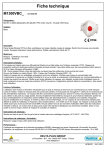
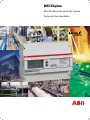
DELTAplus
DIN Rail Mounted electricity meters
Technical Documentation
DELTAplus
Table of Contents
DELTAplus
General Description .......................................................................................................... 4
Chapter 1:
Assortment ......................................................................................................................... 5
Assortment
Direct connected meters .................................................................................................... 6
Assortment
Transformer connected meters .......................................................................................... 7
Assortment
Accessories ........................................................................................................................ 8
Chapter 2:
Technical Data ................................................................................................................... 9
Wiring Diagrams and Pulses ............................................................................................. 11
Chapter 3
with LON-bus and M-bus Communication ......................................................................... 12
with EIB communication ..................................................................................................... 13
Chapter 4:
Symbols, Definitions and Dimensions ............................................................................... 14
Chapter 5:
Electricity Metering ............................................................................................................ 15
1
2
3
4
5
All information in this publication may be subject to change without prior notice
DELTAplus
DELTAplus
General Description
Assortment
The DELTAplus Meter is an electronic electricity meter for DIN rail mounting in distribution boards or small
enclosures. The meter is designed according to ABB’s ProM standard.
Features
The DELTAplus Meter is easy to read with its LCD (Liquid Crystal Display) with 7 mm high digits and
several symbols.
The meter has a polarity independent, solid state (semiconductor) relay that generates pulses proportionally to the measured energy.
A red LED (Light Emitting Diode) flashes proportionally to the energy measured. The DELTAplus Meter
can be equipped with inputs or outputs for control and alarm handling as well as pulse counting. The
meter is equipped with unique instrumentation functions enabling it to read the essential electrical units.
Communication
DELTAplus Meters with integrated EIB, M-bus or LON-bus communication, are easy to read remotely in a
cost-effective way without conversions via traditional pulsed output. The DELTAplus meter is also equiped
with an IR output that can be connected to the ABB Serial Communication Adapter.
Programming
Selection of the information in the LCD-display and programming of the DELTAplus Meter is performed via
two programming buttons. These buttons can be sealed.
Installation check
An installation check that controls the installation runs all the time on all DELTAplus Meters.
Primary measurement function
The DELTAplus Meter offers a primary measurement function when connected to external voltage (VT) or
current (CT) transformers. The VT and CT transformer ratios, can easily be set with the two programming
buttons. This function enables the real energy consumtion to be displayed.
Type Approved
All DELTAplus Meters are type approved according to the international standards IEC 61036 (for active
energy) and IEC 61268 (for reactive energy). These standards cover all technical aspects, climate conditions, electromagnetic compatibility (EMC), electrical and mechanical requirements, and accuracy. The
DELTAplus meter carries approval from ie. PTB, NMI and the Swedish National Testing and Research
Institute, as a revenue classified meter.
Instrumentation
There are instrumentation functions in DELTAplus meters which enable it to read essential electrical units.
This means that the user can read out the following from the DELTAplus meters:
-Power in kW
-Current in A
-Voltage in V
-Frequency in Hz
-Power factor
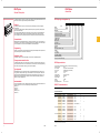
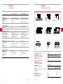
DELTAplus type designation key
Pos
1
Basic
Standard
D or S
Measuring
Active - CT/VT connected
Active - direct connected
Active & reactive - CT/VT connected
Active & reactive - direct connected
Communication
Pulses, Ir-port
Mbus, Ir-port
Lon, Ir-port
EIB, pulses, Ir-port
Accuracy
Class 1
Class 2 (DB...And DD...types)
Voltage
1 x 57-288 V
3 x 100-500 V
3 x 57-288 / 100-500V
Optional functionality
See ”type” columns for last digits
2
3
4
5
6-8
A
B
C
D
1
B
M
L
E
1
2
1
2
3
xxx
DELTAplus, main data
-Fully conform to IEC 61036
-Direct connected
-CT connected
-CT-VT ratios
-Accuracy
-Tariff
-Communication
-Installation check
-Instrumentation
-Display
-IR output
-Operating temperature
(active energy) and IEC 61268 (reactive energy)
5(80)
1(6) can be used for transformers
programmable (up to 999 999)
class 1 and 2
2 or 4
pulse and/or serial
automatic
yes
7 digits
yes
-40° C to +55° C
DIRECT Connected meters
Pulse/IR communication
VOLTAGE
ARTICLE NO.
ABB ID
MEASURING
3x57-288/ DBB 23000
100-500
DBB 23001
DBB 23002
DBB 13000
DBB 13001
DDB 13000
TYPE
0980800
0980811
0980813
0980801
0980812
0980810
2CMA180800R1000
2CMA180811R1000
2CMA180813R1000
2CMA180801R1000
2CMA180812R1000
2CMA180810R1000
Active
Active
Active
Active
Active
Active & Reactive
2
2
2
1
1
1
3x100-500 DBB 22000
DBB 22001
DBB 22002
0980802
0980815
0980803
2CMA180802R1000
2CMA180815R1000
2CMA180803R1000
Active
Active
Active
2
2
2
2
4
1x57-288
0980804
0980816
0980817
0980818
2CMA180804R1000
2CMA180816R1000
2CMA180817R1000
2CMA180818R1000
Active
Active
Active
Active
2
2
1
1
2
2
2
DBB
DBB
DBB
DBB
21000
21001
21002
11001
CLASS
TARIFFS
I/O
ADD.PULSE OUTPUT
2
4
2
For other types, please contact Customer service
4
ABB
ABB
5
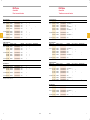
DELTAplus
DELTAplus
Assortment
Direct connected meters
Assortment
Transformer connected meters
Pulse/IR communication
M-bus communication
VOLTAGE
1
TYPE
ARTICLE NO.
ABB ID
MEASURING
3x57-288/ DBM 23000
100-500
DBM 23001
DBM 23002
DBM 23070
DBM 23020
0980840
0980850
0980851
0980852
0980841
2CMA180840R1000
2CMA180850R1000
2CMA180851R1000
2CMA180852R1000
2CMA180841R1000
Active
Active
Active
Active
Active
2
2
2
2
2
3x100-500 DBM 22000
DBM 22001
DBM 22002
0980842
0980853
0980854
2CMA180842R1000
2CMA180853R1000
2CMA180854R1000
Active
Active
Active
2
2
2
1x57-288
0980843
2CMA180843R1000
Active
2
DBM 21000
CLASS
TARIFFS
I/O
VOLTAGE
ADD.PULSE OUTPUT
2
4
1
2
2
4
LON-bus communication
TYPE
ABB ID
MEASURING
CLASS
TARIFFS
0980806
0980808
0980870
0980872
0980871
0980873
2CMA180806R1000
2CMA180808R1000
2CMA180870R1000
2CMA180872R1000
2CMA180871R1000
2CMA180873R1000
Active
Active & Reactive
Active
Active & Reactive
Active
Active & Reactive
1
1
1
1
1
1
2
2
4
4
3x100-500 DAB 12000
DCB 12000
0980807
0980809
2CMA180807R1000
2CMA180809R1000
Active
Active & Reactive
1
1
1x57-288
0980819
2CMA180819R1000
Active
1
DAB 11000
I/O
ADD.PULSE OUTPUT
1
M-bus communication
VOLTAGE
TYPE
ARTICLE NO.
ABB ID
MEASURING
3x57-28 /
100-500
DBL
DBL
DBL
DBL
23000
23003
23004
23070
0980820
0980829
0980830
0980821
2CMA180820R1000
2CMA180829R1000
2CMA180830R1000
2CMA180821R1000
Active
Active
Active
Active
2
2
2
2
3x100-500 DBL 22000
DBL 22003
DBL 22004
0980822
0980831
0980832
2CMA180822R1000
2CMA180831R1000
2CMA180832R1000
Active
Active
Active
2
2
2
1x57-288
0980833
2CMA180833R1000
Active
2
DBL 21000
ARTICLE NO.
3x57-288/ DAB 13000
100-500
DCB 13000
DAB 13001
DCB 13001
DAB 13002
DCB 13002
CLASS
TARIFFS
I/O
ADD.PULSE OUTPUT
VOLTAGE
2
4
ARTICLE NO.
ABB ID
MEASURING
3x57-288/ DAM 13000
0980844
2CMA180844R1000
Active
1
100-500
DCM 13000
DAM 13001
DAM 13002
DAM 13070
DCM 13070
0980847
0980855
0980856
0980845
0980848
2CMA180847R1000
2CMA180855R1000
2CMA180856R1000
2CMA180845R1000
2CMA180848R1000
Active & Reactive
Active
Active
Active
Active & Reactive
1
1
1
1
1
3x100-500 DAM 12000
0980846
2CMA180846R1000
Active
1
1
2
4
TYPE
CLASS
TARIFFS
I/O
ADD.PULSE OUTPUT
2
4
1
1
LON-bus communication
EIB communication
VOLTAGE
TYPE
VOLTAGE
ARTICLE NO.
ABB ID
MEASURING
3x57-288/ SBE 23000
100-500
SBE 23004
SBE 13000
99839053
99839055
99839049
2CMA139053R1000
2CMA139055R1000
2CMA139049R1000
3x100-500 SBE 22000
99839052
1x57-288
99839051
SBE 21000
CLASS
TARIFFS
Active
Active
Active
2
2
1
4
2CMA139052R1000
Active
2
2CMA139051R1000
Active
2
I/O
ADD.PULSE OUTPUT
For other types, please contact Customer service
ARTICLE NO.
ABB ID
MEASURING
3x57-288/ DAL 13000
TYPE
0980823
2CMA180823R1000
Active
1
100-500
DCL 13000
DAL 13003
DAL 13004
DAL 13070
0980828
0980834
0980835
0980824
2CMA180828R1000
2CMA180834R1000
2CMA180835R1000
2CMA180824R1000
Active & Reactive
Active
Active
Active
1
1
1
1
3x100-500 DAL 12000
DCL 12000
DAL 12070
0980825
0980836
0980826
2CMA180825R1000
2CMA180836R1000
2CMA180826R1000
Active
Active & Reactive
Active
1
1
1
CLASS
TARIFFS
I/O
ADD.PULSE OUTPUT
2
4
1
1
EIB communication
VOLTAGE
ARTICLE NO.
ABB ID
MEASURING
3x57-288/ SAE 13000
TYPE
99839046
2CMA139046R1000
Active
CLASS
1
100-500
SCE 13000
SAE 13004
99839056
99839048
2CMA139056R1000
2CMA139048R1000
Active & Reactive
Active
1
1
3x100-500 SAE 12000
99839045
2CMA139045R1000
Active
1
TARIFFS
I/O
ADD.PULSE OUTPUT
4
For other types, please contact Customer service
6
ABB
ABB
7
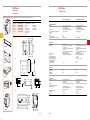
DELTAplus
DELTAplus
Assortment
Accessories
Technical Data
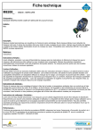
The table below, figures, and drawings describe the DELTAplus accessories.
1
ARTICLE NO.
ABB ID
TYPE
APPLICATION
99
99
09
09
09
09
19
2CMA137090R1000
2CMA137091R1000
2CMA132540R1000
2CMA132633R1000
2CMA132541R1000
2CMA132635R1000
GHV210859R00224
Serial Comm. Adapter
Serial Comm. Adapter
DIN-rail
Long cover
External counter
Front mounting kit
Time switch clock
for tariff control
STT 227
M-Bus
RS232
Wall mounting
Wall mounting
Panel mounting
Panel mounting
837
837
811
811
811
811
102
090
091
02
81
04
84
30
99 837 090 / 91
D. 1
DIRECT CONNECTED METERS
TRANSFORMER-RATED METERS
3 x 57-288 / 100-500 (4-wire)
3 x 100-500 (3-wire)
1 x 57-288 (Single phase)
-20% to +15% of nominal voltage
< 3 VA, 2 W/phase
3 x 57-288 / 100-500 (4-wire)
3 x 100-500 (3-wire)
1 x 57-288 (Single phase)
-20% to +15% of nominal voltage
< 3 VA, 2 W/phase
5
80
< 20
< 6 VA/phase
1
6
<2
< 0.08 VA/phase
DRAWING
1
1
2
3
4
-
VOLTAGE/CURRENT UNITS
Voltage [V]
Voltage range
Power consumption of voltage circuits
Current [A]
- base
- max
Starting current [mA]
Power consumption of current circuits
60
45
35
2
GENERAL DATA
Frequency [Hz]
Standards
90
45
09 811 02
Display of energy
Accuracy
Voltage transformer ratio
Current transformer ratio
Maximum transformer ratio
Connection area [mm2]:
• Current terminals
• Voltage terminals
64
D. 2
50/60 ± 5%
• IEC 61036 for active energy meters
of class 1 and 2
• IEC 61268 for reactive energy meters
of class 2
• Pulse output according to DIN 43864
(SO) IEC 62053-31
LCD with 7 digits, height 7 mm
According to IEC 61036 Cl. 1
1 - 9 999
1 - 9 999
CT x VT max = 999 999
1.0 - 25
0.5 - 10
0.5 - 10
122.5
97
337.5
7
122.5
97
303.5
7
According to IEC 60695-2-1:
• Terminal 960° C
• Cover 650° C
75% yearly average, 95% on 30 days/year
According to IEC 60695-2-1:
• Terminal 960° C
• Cover 650° C
75% yearly average, 95% on 30 days/year
According to IEC 60529:
• IP20 on terminal block without
protective enclosure
According to IEC 60529:
• IP20 on terminal block without
protective enclosure
-40 to +55
-40 to +70
-40 to +55
-40 to +70
110.5
09 811 81
50/60 ± 5%
• IEC 61036 for active energy meters
of class 1 and 2
• IEC 61268 for reactive energy meters
of class 2
• Pulse output according to DIN 43864
(SO) IEC 62053-31
LCD with 7 digits, height 7 mm
According to IEC 61036 Cl. 2 or Cl. 1
DIMENSIONS
122.5
09 811 04
Width [mm]
Height [mm]
Weight [g]
DIN modules
50
D. 3
1
54,1
2,5
ENVIRONMENT
20
23
Resistance to heat and fire
Humidity
Protection against penetration
of dust and water
34
31
6
09 811 84
Temperature range [°C]:
•Operating
•Storing
D. 4
100
80
45,5
2
65
123,5
161
50
19 102 30
8
60
ABB
ABB
9
DELTAplus
DELTAplus
Technical Data
Wiring Diagrams and Pulses
DIRECT CONNECTED METERS
TRANSFORMER-RATED METERS
0 - 2.5 (For combined meters 0 - 0.5)
0 - 247 AC/DC (polarity independent)
0 - 100
100
Programmable
0 - 2.5 (For combined meters 0 - 0.5)
0 - 247 AC/DC (polarity independent)
0 - 100
100
Programmable (primary registering)
1000
40
5000 (secondary registering)
40
PULSE OUTPUT
Connection area [mm2]
External pulse voltage [V]
Maximum current [mA]
Pulse length [ms]
Pulse frequency
DBB23XXX
DBB21XXX
DBB22XXX
VISIBLE PULSE INDICATOR
Red LED with frequency [imp/kWh]
Pulse width [ms]
2
2
ELECTROMAGNETIC COMPATIBILITY (EMC)
Impulse voltage test
Fast transient burst test [kV]
Radio frequency immunity
Immunity to conducted disturbance
Radio frequency emission
Electrostatic discharge (ESD) [kV]
6 kV 1.2/50µs (IEC 600-60)
4 (IEC 61000-4-4)
80 MHz - 1 GHz at 10 V/m (IEC 61000-4-3)
150 kHz - 80 MHz (IEC 61000-4-6)
According to CISPR 22 class B
15 (IEC 61000-4-2)
6 kV 1.2/50µs (IEC 600-60)
4 (IEC 61000-4-4)
80 MHz - 1 GHz at 10 V/m (IEC 61000-4-3)
150 kHz - 80 MHz (IEC 61000-4-6)
According to CISPR 22 class B
15 (IEC 61000-4-2)
Transparent front glass, bottom case, upper
case and terminal cover
Polycarbonate
Polycarbonate
Terminal block
Protection class
Glow wire test
Glass-fibre reinforced polycarbonate
II
According to IEC 60 695-2-1
Glass-fibre reinforced polycarbonate
II
According to IEC 60 695-2-1
DAB13XXX
DAB11XXX
DAB12XXX
MATERIAL
21
20
22
kWh
fig.1
21
kWh
kvarh
fig.2
20
fig.3
TARIFF INPUTS (OPTIONAL)
Maximum voltage [V]
Maximum wire size [mm2]
Input voltage range [V]
Terminal wire area [mm2]
Lon and M-bus
EIB
276 AC
2.5
0 - 20 AC (“voltage off")
57 - 276 AC ("voltage on")
276 AC
2.5
0 - 20 AC (“voltage off")
57 - 276 AC ("voltage on")
0-2.5
0.5
0-2.5
0.5
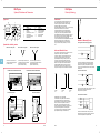
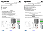
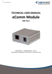
Direct connected meters
Three phase system
With neutral conductor (see DBB23XXX)
Without neutral conductor (see DBB22XXX)
One phase system
With neutral conductor (see DBB21XXX)
Transformer rated meters
Three phase system
With neutral conductor (see DAB13XXX)
Without neutral conductor (see DAB12XXX)
Tariff input
ACTIVE TARIFF
INPUT (T1)
INPUT (T2)
Tariff
Tariff
Tariff
Tariff
0*
1**
0
1
0
0
1
1
1
2
3
4
*0 means < 20V
**1 means > 57V - 276V
Pulse frequency
One phase system
With neutral conductor (see DAB11XXX)
Tariff input
Tariff control by external power supply up to 230 V AC(see fig.1)
T1 = tariff input 1
T2 = tariff input 2
Pulse output
External power supply up to 247 V AC or DC.
Active energy meters (see fig.2)
Combined meters (see fig.3)
10
ABB
ABB
DIRECT CONNECTED METERS
[IMP/KWH]
1
10
100
500
640
1 000
5 000
TRANSFORMER-RATED METERS
[IMP/KWH PRIMARY REGISTERING]
0.01
0.1
1
10
100
500
640
1000
11
DELTAplus
DELTAplus
with LON-bus and M-bus Communication
with EIB Communication
Inputs or Outputs (option)
Installation (LON-bus)
The meter can be provided with inputs and outputs. The input can
be used as a sabotage alarm or as a pulse counter, e.g., for a
water meter. The output can be used as an ON and OFF function,
for example to switch off the current by remote control. The
inputs/outputs are of the opto-switch type and are galvanically isolated from other electronics in the meter. There are two input/
output voltage variants; high and low, see technical data. Both variants are for AC/DC voltage and are polarity independent.
Additional EIB DELTAplus meter Features:
Gren/Red LED
Integrated EIB communication interface
Service Pin
Remote reading of the following meter data:
Set Scroll
Control of the following meter functions:
Network monitoring function:
LON-bus
Automatic check function for wiring with “installation self-test”
C
INP
C
OUT
13
15
13
15
Technical Data of EIB-Connection
Network log:
ABB i-bus® EIB connection:
Number of participants:
Transmission medium:
Line lengths:
LonWorks network,
polarity insensitive
Installation (M-bus)
M-bus
Input/output block
3
Meter readings in Wh (varh)
Current capacity W (var)
Meter status and error information.
Change of charges, synchronised inquiry of meter readings and
Management of error information.
Logging and display of up to 24 electrical measured variables.
C
INP1
INP2
C
OUT1
OUT2
C
OUT1
INP2
13
15
16
13
15
16
13
15
16
Set
ABB i-bus® EIB (European Installation Bus)
Bus supply terminal at the front (top)
Max. 64 per line (potential total of 14,000 participants)
Twisted pair, YCYM or J-Y(St)Y 2x2x0.8 mm
Total length of single line ≤ 1,000 m
-between two participants ≤ 700 m
-between power supply and participant ≤ 350 m
3
Scroll
For more technical details of the DELTAplus with EIB connection, please contact your local ABB EIB sales organisation.
Functions Inputs and Outputs
The input counts and stores pulses. The status can be read both
via the bus and on the LCD display. The output can be controlled
from a PC by switching ON and OFF and the status can be read at
each transmission of data from the meter.
M-Bus network,
polarity insensitive
LON-bus Protocol
The software is compatible with LonMark 3.2 and uses the
LonMark-profile Utility Data Logger 1.0. A description of network
variables is noted in the DELTAplus User’s Manual, which can be
ordered from ABB.
Instrumentation (Optional)
Read electrical units and functions, depending on type
of DELTAplus meter.
M-bus Protocol
DESCRIPTION
The protocol is based on international standard IEC 870. The bus
system is adapted for remote reading of energy meters and works
on the principle of master slave.
Active energy, total and per tariff
Reactive energy, total and per tariff
Transformer ratio
Status of inputs and outputs
Current and voltage per phase
Active power per phase and total
Reactive power per phase and total
Apparent power per phase and total
Power factor, line frequency
Status on installation check
Interruption counter for line voltage
Manufacturer and serial number
Calling direction (master to meter)
UMark
Start
1
2
3
4
5
6
7
8
Parity
Stop
8
Parity
Stop
UMark
-10V
Replying direction (meter to master)
IMark
+(11-20)mA
Start
1
2
3
4
5
6
7
Technical data
IMark
INPUT
Technical Information
Operating and display elements: Service pin and LED. Bus
interference: FTT-10A. Communication rate: 78 kbps.
A software clock is implemented in the Lon-interface to enable
readings from the meter to be time-recorded. The clock is based
on a timer in the Neuron and is to be set following a power failure.
It copes with leap years but not daylight-saving time. The accuracy
is ± 2 seconds per 24 hours.
12
Voltage range
Input resistance
Min. pulse length and pause
0-40 V AC/DC
0-2 V no pulse count
4.5-40 V pulse count
8-13 kohm
30 mS
OUPUT
Voltage range
Output resistance
Max. current
0-400 VDC, 0-282 V AC
12-36 ohm
120 mA
ABB
ABB
13
DELTAplus
DELTAplus
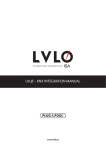
Symbols, Definitions and Dimensions
Electricity Metering
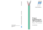
Type label
Introduction
13
1
2
3
4
5
12
6
7
11
10
9
NO.
SYMBOL
NO.
SYMBOL
1.
2.
3.
4.
5.
6.
7
Type designation
Voltage
Frequency
Nominal and max. current
Accuracy class
Pulse output frequency
LED frequency
8
9
10
11
12
13
Serial number
Week of manufacture
Year of manufacture
Protective class
Approval symbols
Network type
8
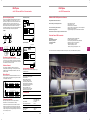
Symbols for electricity meters
Meters with 1 drive system
Meters with 2 drive systems
In most cases, the three-watt meter method is used for
power measurements in three phase systems with a
current-carrying neutral conductor. Where metering is
the basis for billing, this is a requirement.
High voltage installations often do not have any current-carrying
neutral conductor, therefore the two-watt meter
measurement method can be used. Both voltage and
current transformers are commonly used. Single phase
metering can be used if a three-phase load is balanced.
If the DELTAplus meter is directly connected to the mains, the
device must be protected by fuses (the possibility to isolate
the meter is recommended) on the incoming side.
In order to allow maintenance of DELTAplus Meters with current
transformers connected, a short circuiting terminal
block should be installed near the meter. The voltage
supply to the meter must be protected by a max. 10A
fuse.
Methods of Measuring Power
The single-watt meter method (single phase)
Meters with 3 drive systems
Active and Reactive Power
4
which have one current and one
voltage coil (used for single phase
2-conductor circuits)
each with a voltage and current coil
connected as per the two watt-meter
method (used for the three
phase 3-conductor circuits).
Terminal area, transformer-rated meter
Load
Active power is needed to perform work. However, consumer
equipment often cause a phase shift between
current and voltage as a result of the inductive nature of
the load, for example in motor drives. The maximum
permissable phase shift is governed by the terms of the
consumers’ contract with the electricity supplier. If the
consumers exceed the specified maximum, they will be
liable to an extra charge and would be well advised to
install compensation equipment, usually in the form of
capacitor banks. Thus it can be seen that the reactive
component of the power also is of interest for measurement.
each with a voltage and current coil
connected as per the three watt-meter
method (used for the three
phase 4-conductor circuits).
Terminal area, direct connected meter
I
U
P= 3 x IT x UT
In three phase systems the single-watt meter method
only gives correct results with a symetrical load on the
phases. Since in practice perfectly balanced systems
are very rare, this method should not be used for accurate
measurements.
The two-watt meter method
U
U
U
I
U
1 2 3 4 5 6 7 8 9 11
15
8
U
15,5
18,5
5
Load
N
7,5
L1 L1 L1 L2 L2 L2 L3 L3 L3
S1 U S2 S1 U S2 S1 U S2
8,5
I
9
5
7
I
122,5
122,5
Resistive
load
Front view, all meters
I
Capacitive
load
Inductive
load
The two-watt meter method is used in three phase systems
without a neutral conductor, irrespective of the
load symetrical or asymetrical.
The three-watt meter method
64,8
Resistive loads cause no phase shifts.
Inductive loads cause a phase shift in one direction,
while capacitive loads produce a phase shift in the
opposite direction. As a result, inductive and capacitive
loads can be used to compensate each other. The
phase shift of the current compared to the voltage
results in the power being divided into active and reactive
components. The angle between the actual power
vector and the active power component is described as
phase displacement angle, often referred to as ϕ.
2
SCROLL
45
96
100
I
Side view, all meters
55,4
SET
5
I
I
Load
I
U
U
U
The three watt-meter method is usually used in three
phase systems having a neutral conductor. This method
can deal with asymetrical and symetrical loads.
8,5
14
50
ABB
ABB
15
2CMC481002D0008/29567
Österbergs & Sörmlandstryck, 25887
Sweden Production:Lennandia Feb 04