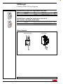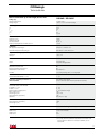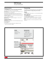
1
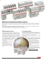
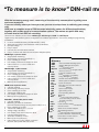
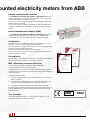
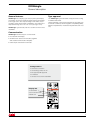
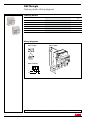
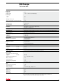
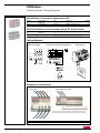
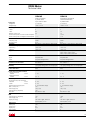
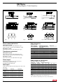
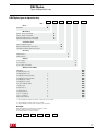
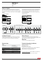
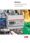
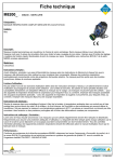
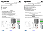
Main Catalogue
Catalogue 2CMC480022C0002, October 2007
Superseedes Catalogue 2CMC480022C0001, December 2006
Electricity meters,
DIN-rail mounted
ODINsingle
DELTAsingle
ODIN
DELTAplus
DIN-rail mounted electricity meters
Modular DIN Rail Products offer a wide range of functions to be integrated in electrical installations with significant
benefits for the user. DIN rail mounted electricity meters are designed for high level performance and are safe and
fast to install.
The DIN rail mounted electricity meters are available in four product lines: ODINsingle and DELTAsingle for single
phase metering and ODIN and DELTAplus for three phase metering.
The meters are available in several configurations to suite many applications.
ABB Automation Products
Low voltage products
The Automation Products division provides products, with
related services, that are used as components in machinery,
switchboards, distribution panels and automation systems.
Due to ABB’s broad program of product stadardization, components of today are the ‘building blocks’ of system solutions,
incorporating functionalities that will allow seamless integration
in real-time automation and information systems.
The Automation Products offering covers a wide range of products and services including power electronics systems, motors and generators, drives, instrumentation, control products,
DIN-rail components, enclosures, wiring accessories, low-voltage switchgear and circuit breakers. All these products help customers to
save energy, improve productivity and
increase safety.
The Automation Products division is
a global business.
Key products include low-voltage
products and systems, drives,
power electronics, motors, machines, instrumentation and product
service.
2
2CMC480022C0002
At the product level, all the low voltage products can operate
together perfectly.
To create a systems solution every product included has to be equipped with the tools necessary
to install, operate and maintain it efficiently
throughout the product life cycle.
The range of low voltage products is
supported by technical documentation. This together with compact
design makes it easier than ever to
incorporate our products in your
system.
Our customers can find all product
related documentation such as
brochures, catalogues, selection program, certificates, drawings and other
information directly at
www.abb.com/lowvoltage.
Electricity meters,
DIN-rail mounted
Contents
Page
DIN-rail mounted electricity meters, General description.........................................4
DIN-rail mounted electricity meters, Selection guide...............................................6
ODINsingle
General description................................................................................................9
Ordering details....................................................................................................10
Wiring diagrams...................................................................................................10
Technical data......................................................................................................11
DELTAsingle
General description..............................................................................................13
Ordering details....................................................................................................14
Wiring diagrams...................................................................................................14
Technical data......................................................................................................15
ODIN Meter
General description..............................................................................................17
Ordering details....................................................................................................18
Wiring diagrams...................................................................................................18
Technical data......................................................................................................19
DELTAplus
General description..............................................................................................21
Ordering detalis
Direct connected meters.............................................................................22
Transformer connected meters...................................................................23
Technical data......................................................................................................24
Wiring diagram.....................................................................................................26
Pulse frequency....................................................................................................26
Type designation key............................................................................................27
Options
I/O..............................................................................................................28
Log functions .............................................................................................29
Serial Communication Adapter (SCA)
General description..............................................................................................30
Ordering details....................................................................................................32
Accessories
Ordering details....................................................................................................32
DIN-rail mounted electricity meters
Symbols, definitions and methods of measuring power........................................33
Dimensions...........................................................................................................34
The products described in this catalogue are subject to change (design,
dimensions, technical data, etc.) without prior notice.
3
2CMC480022C0002
“To measure is to know” DIN-rail mo
With the increasing energy cost, measuring of the electricity consumption is getting more
and more important.
If you can identify where you have your use you are one step closer to reducing your energy
cost.
ABB have a complete range of DIN-mounted electricity meters for different applications,
together with a wide range of communication options. The meters are quick and easy
to install due to their DIN-rail mounting.
There are four different product lines: ODINsingle, DELTAsingle, ODIN and DELTAplus.
Together they offer several types of configurations for different applications due to their intelligent programming
possibilities.
• In House certified laboratory (SS-EN/ISO/IEC 17025)
• Approved according to international & national standards
• Compact design
• Easy to install
• Infra-red (IR) communication interface
• Easy to combine with Serial Communication Adapters (SCA)
ODINsingle, 1-phase meter
• Single phase measuring
• Active energy, accuracy class B (Cl. 1)
• Direct metering up to 65A
• LCD display, Pulse and IR output for SCA
• Internal clock for 1, 2 and 4 tariffs and
monthly values
DELTAsingle, 1-phase meter
• Single phase measuring
• Active energy, accuracy class B (Cl. 1)
• Direct metering up to 80A
• LCD display, Pulse and IR output for SCA
• Internal clock for 1, 2 and 4 tariffs and
monthly values
• Memory back-up (EEprom)
ODIN, basic 3-phase meter
• 3 phase metering
• Active energy, accuracy class 2
• Direct metering up to 65A
• Transformer metering 5A
• LCD display, Pulse and IR output for SCA
• Memory back-up (EEprom)
DeltaPlus, advanced 3-phase meter
• 3 phase metering
• Measuring of Active or Combined
(Active and reactive) energy, accuracy class A & B (Cl. 2 & 1)
• Direct metering up to 80A
• Transformer metering for 1, 2 or 5A
• Voltage range 100-500V
• LCD display, Puls and IR output for SCA
• Instrumentation (Analyzer)
• Automatic installation control
• Memory back-up (EEprom)
• Internal Clock for mothly values, maximum
demand, load profile tariff and control
4
2CMC480022C0002
Glossary
AMR
Automatic Meter Reading system
BMS
Building Management System
DST
Daylight Savings Time
EEprom Electrically Erasable programmable
read-only memory
EIB
European Installation Bus
EMC
Electromagnetic compatibility
EMS
Energy Management System
GPRS
General Packet Radio Service
GSM
Global system for Mobile communication
I/O
Inputs and Outputs
IR-port Infra-Red communication interface
LAN
Local Area Network
LCD
Liquid Crystal Display
LED
Light Emitting Diode
LON
Local Operating Network
M-bus
Meter bus
MID
Measuring Instrument Directive
(Common testing rules for all EU
and EES countries)
OTA
Over The Air
PSTN
Public Switched Telephone Network
RTC
Real Time Clock
SCA
Serial Communication Adapter
SMS
Short Message Service
SP
Sveriges Tekniska Forskningsinstitut
(Technical Research Institute of Sweden)
TCP
Transmission Control Protocol
UDP
User Datagram Protocol
ounted electricity meters from ABB
Flexible communication solution
The ODINsingle, DELTAsingle, ODIN and DELTAplus electricity
meters offer flexible solutions for communication with a standard
pulse/LED output or an infrared (IR) port.
The IR port can be connected to any of the Serial Communication
Adapters (SCA) avavilable.
Due to open protocols and the possibility to add a SCA later the
installation is flexible and adaptable to any future communication
needs.
Serial Communication Adapter (SCA)
The ODINsingle, DELTAsingle, ODIN and DELTAplus electricity
meters have an IR output for remote reading of metered data.
The adapter converts the optical signals to a electrical signal.
Certification
All ABB meters are certified according to IEC 62052-11 and IEC
62053-21. This is the best quality guarantee there is.
Our procedures for design and production are 3rd party approved
by BVC according to ISO 9001:2000.
This ensures high quality design and production.
That is why you can always trust the accuracy of an ABB DIN rail
mounted electricity meter.
Accreditation
Our laboratory is accredited by SWEDAC according to SS-EN/ISO/
IEC 17025 for initial verification of Electricity meters.
MID – Measuring Instrument Directive
The European parliament decided in 2004 to establish
a new directive for measuring instrument.
The MID directive took affect at the 30th of October 2006 and each
member country has to take this directive into the national legislation
latest April 2006.
The MID directive means:
• Common testing rules based on IEC standards for all EU and
EES countries.
• No need for local testing/approval. Test performed in one EU
country must be accepted in all EU and EES countries.
• No special national requirements of any kind are allowed.
On the product as well as on the packing you find a label certifying
that the ABB electricity meter is tested and approved according
to MID directive.
Test standard
M06
0402
A new standard EN 50470-1, -3 will replace IEC 62053-11 and
IEC 62052-23 in EU and EES countries.
5
2CMC480022C0002
ODINsingle
Single phase
DELTAplus
Single phase
DELTAsingle
Selection Guide
3 phase
DELTAplus
ODIN
3 phase + N
3 phase + N
DELTAplus
Single phase
3 phase
DELTAplus
ODIN
3 phase + N
6
2CMC480022C0002
3 phase + N
Network
Type
Max. current Voltage Active Reactive
Direct
(V) (50/60Hz)
energy
energy
Connection
Single phase
65
230
Yes
—
Single phase
65
230
Yes
—
Single phase
Single phase
Single phase
80
80
80
230
230
230
Yes
Yes
Yes
—
—
—
Single phase
Single phase
Single phase
80
80
80
230
230
230
Yes
Yes
Yes
—
—
—
3 phase
80
100 - 500
Yes
—
3 phase
3 phase
80
80
100 - 500
100 - 500
Yes
Yes
—
—
3 phase
3 phase
80
80
100 - 500
100 - 500
Yes
Yes
—
—
3 phase + N
65
230/400
Yes
—
3 phase + N
3 phase + N
3 phase + N
80
80
80
57-288 / 100-500
57-288 / 100-500
57-288 / 100-500
Yes
Yes
Yes
—
—
Yes
3 phase + N
3 phase + N
3 phase + N
80
80
80
57-288 / 100-500
57-288 / 100-500
57-288 / 100-500
Yes
Yes
Yes
—
—
Yes
3 phase + N
3 phase + N
3 phase + N
80
80
80
57-288 / 100-500
57-288 / 100-500
57-288 / 100-500
Yes
Yes
Yes
—
—
—
3 phase + N
3 phase + N
80
80
57-288 / 100-500
57-288 / 100-500
Yes
Yes
—
—
Max. current
Transformer
Connection
Single phase
Single phase
6 (1,2,5)
6 (1,2,5)
57 - 288
57 - 288
Yes
Yes
—
Yes
3 phase
3 phase
6 (1,2,5)
6 (1,2,5)
100 - 500
100 - 500
Yes
Yes
—
Yes
3 phase
3 phase
6 (1,2,5)
6 (1,2,5)
100 - 500
100 - 500
Yes
Yes
—
Yes
3 phase
6 (1,2,5)
100 - 500
Yes
Yes
3 phase + N
10 (5)
230/400
Yes
—
3 phase + N
3 phase + N
6 (1,2,5)
6 (1,2,5)
57-288 / 100-500
57-288 / 100-500
Yes
Yes
—
—
3 phase + N
3 phase + N
3 phase + N
6 (1,2,5)
6 (1,2,5)
6 (1,2,5)
57-288 / 100-500
57-288 / 100-500
57-288 / 100-500
Yes
Yes
Yes
—
—
Yes
3 phase + N
3 phase + N
3 phase + N
6 (1,2,5)
6 (1,2,5)
6 (1,2,5)
57-288 / 100-500
57-288 / 100-500
57-288 / 100-500
Yes
Yes
Yes
—
—
Yes
3 phase + N
6 (1,2,5)
57-288 / 100-500
Yes
—
3 phase + N
3 phase + N
6 (1,2,5)
6 (1,2,5)
57-288 / 100-500
57-288 / 100-500
Yes
Yes
—
Yes
Built in
comm.
Internal
Instrumen-
Accuracy Tariffs
Pulse
Type Clock
tation
Class
output
code Ref
page
No.
IR
—
—
B (Cl. 1)
1
—
OD1065
10
IR
—
—
B (Cl. 1)
1
Yes
OD1365
10
IR
IR
IR
—
Yes *
Yes *
—
—
—
B (Cl. 1)
B (Cl. 1)
B (Cl. 1)
1
2
4
Yes
Yes
Yes
FBB11200
FBB11205
FBB11206
14
14
14
IR
IR
IR
—
Yes *
Yes *
—
—
—
B (Cl. 1)
B (Cl. 1)
B (Cl. 1)
1
2
4
—
—
—
FBU11200
FBU11205
FBU11206
14
14
14
IR
—
Yes
A (Cl. 2)
1
Yes
DBB22000
22
LON+IR
LON+IR
—
—
Yes
Yes
A (Cl. 2)
A (Cl. 2)
2
4
—
—
DBL22003
DBL22004
22
22
Mbus+IR
Mbus+IR
—
—
Yes
Yes
A (Cl. 2)
A (Cl. 2)
2
4
—
—
DBM22001
DBM22002
22
22
IR
—
—
Cl. 2
1
Yes
OD4165
18
IR
IR
IR
—
Yes
—
Yes
Yes
Yes
A (Cl. 2)
A (Cl. 2)
B (Cl. 1)
1
1
1
Yes
Yes
Yes
DBB23000
DBB23007
DDB13000
22
22
22
LON+IR
LON+IR
LON+IR
—
—
—
Yes
Yes
Yes
A (Cl. 2)
A (Cl. 2)
A (Cl. 2)
2
1
1
—
Yes
—
DBL23001
DBL23070
DDL23000
22
22
22
Mbus+IR
Mbus+IR
Mbus+IR
—
—
—
Yes
Yes
Yes
A (Cl. 2)
A (Cl. 2)
A (Cl. 2)
1
2
4
—
—
—
DBM23000
DBM23003
DBM23004
22
22
22
Mbus+IR
Mbus+IR
Yes
—
Yes
Yes
A (Cl. 2)
A (Cl. 2)
1
1
—
Yes
DBM23007
DBM23070
22
22
IR
IR
—
—
Yes
Yes
B (Cl. 1)
B (Cl. 1)
1
1
Yes
Yes
DAB11000
DCB11000
23
23
IR
IR
—
—
Yes
Yes
B (Cl. 1)
B (Cl. 1)
1
1
Yes
Yes
DAB12000
DCB12000
23
23
LON+IR
LON+IR
—
—
Yes
Yes
B (Cl. 1)
B (Cl. 1)
1
1
Yes
—
DAL12070
DCL12000
23
23
Mbus+IR
—
Yes
B (Cl. 1)
1
Yes
DCM12070
23
IR
—
—
Cl. 2
1
Yes
OD4110
18
IR
IR
—
—
Yes
Yes
B (Cl. 1)
B (Cl. 1)
1
2
Yes
Yes
DAB13000
DAB13001
23
23
IR
IR
IR
—
Yes
—
Yes
Yes
Yes
B (Cl. 1)
B (Cl. 1)
B (Cl. 1)
4
1
1
Yes
Yes
Yes
DAB13002
DAB13007
DCB13000
23
23
23
LON+IR
LON+IR
LON+IR
—
—
—
Yes
Yes
Yes
B (Cl. 1)
B (Cl. 1)
B (Cl. 1)
2
4
1
—
—
—
DAL13003
DAL13004
DCL13000
23
23
23
Mbus+IR
Yes
Yes
B (Cl. 1)
1
—
DAM13007
23
Mbus+IR
Mbus+IR
—
—
Yes
Yes
B (Cl. 1)
B (Cl. 1)
1
1
Yes
—
DAM13070
DCM13000
23
23
*) Internal Clock for tariff control and monthly energy values
7
2CMC480022C0002
ODINsingle
1-phase meter
ODINsingle is a compact, single phase electricity meter for direct connection up to 65 A. The
small size and the DIN rail mounting makes it suitable for installation in distribution boards
and small standard enclosures.
Key product features are clear markings on the front that are easy to understand, robust connection terminal and a backlit display that is very easy to read.
ODINsingle, 1-phase meter
ODINsingle
• Single phase measuring
General description.................................................. 9
• Active energy, accuracy class B (Cl. 1)
Ordering details....................................................... 10
• Direct metering up to 65A
Wiring diagrams....................................................... 10
• LCD display, Pulse output and IR for SCA
Technical data.......................................................... 11
• IEC and MID approval
Accessories............................................................. 32
Dimensions.............................................................. 34
8
2CMC480022C0002
ODINsingle
General description
General features
Type approval
ODINsingle has a display type LCD (Liquid Crystal Display).
The display shows the measured values clearly with 6 digits,
6 mm high. Due to the compact design of the meter, only 2
modules, space will be saved at installation. The meter has a
temperature range from -25 ˚C to +55 ˚C (storage +70 ˚C).
ODINsingle, type OD1365, has two counters of which one is
resettable.
The ODINsingle types are tested and approved according
to different standards.
These standards cover technical aspects of the meter such
as climate conditions, electromagnetic compatibility (EMC),
electrical requirements, mechanical requirements and accuracy.
Communication
ODINsingle has three ways to communicate:
• Front backlit LCD display.
• IR interface for serial communication (together
with a Serial Communication Adapter).
• Pulse output as standard on OD1365.
Strong features
• 65A Direct connection
• Low starting current, 20 mA
• IEC approval, MID approval
• IR interface
• OD1365 one counter is resettable
Display info
• Load indicator
• Communication active
• Backlit LCD
9
2CMC480022C0002
ODINsingle
Ordering details, Wiring diagrams
OD1065 direct connected, single phase meter 65 A
Voltage
(V)
Pulse output
Type
Order code
frequency
Weight
kg
230
-
0.135
OD1065
2CMA131040R1000
OD1365 direct connected, single phase meter 65 A,
two counters, resettable, pulse output
Voltage
(V)
Pulse output
Type
Order code
frequency
Weight
kg
230
100 imp/kWh
0.140
OD1365
2CMA131041R1000
Wiring diagrams
Direct connection
• Accessories ................................. page 32
10
2CMC480022C0002
Pulse output
• Technical data..............................page 11
• Dimensions.......................... page 34
ODINsingle
Technical data
Direct connection up to 65A single phase meter
Voltage (V)
Nominal voltage AC Voltage range Current (A)
Imin
Itr
Iref (Ib) Imax Ist
General data
Frequency (Hz) Frequency range Accuracy Class Power consumption at 230 VAC and 5 A
Standards
MID approval according to International approval according to OD1065 / OD1365
1 x 220 - 240
-20% to +15% of nominal voltage
0.25
0.5
5
65
20 mA
50/60
+/-5%
B (Cl.. 1)
1.0 VA
EN 50470-1, EN 50470-3
IEC 62052-11, IEC 62053-21
Temperature range (˚C)
Operating Storage -25 to +55
-25 to +70
Enclosure material
Upper Lower Polycarbonate
Polycarbonate/glass fibre
Environment classes
Mechanical environment
Electromagnetical environment
Resistance to heat and fire
Humidity
Connection area main terminals
Current terminals flexible 1 x mm² M1
E2
IEC 60695-2-1
75% yearly average, 95% on 30 days/year
1 - 16
Protection against penetration of
dust and water
According to IEC 60529:
IP 20 on terminal block without protective enclosure*)
Pulse output (OD1365)
Connection area, main terminals
• Flexible 1 x mm² • Solid 1 x mm² External pulse voltage (V) DC Max. current (mA) Pulse length (ms) Pulse frequency (imp/kWh) Standard 0 - 2.5
0 - 2.5
5 - 40 (Transistor output)
100
100 (± 2.5)
100
IEC 62053-31 (S0)
LED
Pulse frequency (imp/kWh) Pulse length (ms) 1000
40
Display Backlit LCD with 6 digits, 6mm high
Dimensions
Width (mm) Height (mm) Depth (mm) 35.8, 2 DIN modules
85
63.4
*) To comply with the protection requirements the meter must be mounted in a class IP 51 enclosure or better, acc. to
IEC 60529.
11
2CMC480022C0002
DELTAsingle
1-phase meter
DELTAsingle is an advanced single phase electricity meter for active energy. It is designed
for installation on a DIN rail in distribution boards and small enclosures.
Key product features are internal clock for tariff handling and direct metering up to 80 A.
DELTAsingle, 1-phase meter
DELTAsingle
• Single phase measuring
General description.................................................. 13
• Active energy, accuracy class B (Cl. 1)
Ordering details....................................................... 14
• Direct metering up to 80A
Wiring diagrams....................................................... 14
• LCD display, Pulse output and IR for SCA
Technical data.......................................................... 15
• Internal clock for 1, 2 and 4 tariffs and
monthly values
Accessories............................................................. 32
• Memory back-up (EEprom)
• IEC and MID approval
12
2CMC480022C0002
Dimensions.............................................................. 34
DELTAsingle
General description
General features
Programming
The DELTAsingle is an active energy, single phase meter for
direct metering up to 80A. The LCD (Liquid Crystal Display)
has 6 digits, 6mm high to ensure clear reading.
It is possible to choose information shown on the display and
change the settings in the meter using two push buttons. The
push button used for changing settings can be sealed.
DELTAsingle has a compact design, only 4 modules (72 mm)
that saves space in the installation.
Tariffs
In the case of a power failure, the meter is equipped with a
“Super Cap” power backup capacitor that will run the clock for
168 hours at +20˚ C.
A red LED (Light Emitting Diode) on the front flashes proportionally to the energy consumed.
DELTAsingle has a temperature range from –40 to +55º C
(storage +70º C)
Communication
DELTAsingle has 3 ways to communicate depending on type.
• Front LCD display
• Pulse output
• IR interface for serial communication (together with the
serial communication adapter)
The DELTAsingle range includes 1, 2 and 4 tariff meter options.
Type approval
All the DELTAsingle meter types are tested and approved
according to different standards.
These standards covers all technical aspects of the meter
such as climate conditions, electromagnetic compatibility
(EMC),
electrical requirements, mechanical requirements as well as
accuracy.
Unique
Strong features
• IR Port
• 80A direct current
• Internal clock
• Weight, only 150gr
• Low starting current
• Direct = 25mA
• Display Info
• IEC approval, MID approval
• Memory back up (EEprom)
• Clock back up (Super Cap)
• Accuracy class B (Cl.1)
• Tariffs (1, 2, 4)
Display info
• Communication
indicator
• Load indicator
• Tariff indicator
13
2CMC480022C0002
DELTAsingle
Ordering details, Wiring diagrams
Ordering details
No. of Tariffs
Pulse output
Type
Order code
Weight
kg
1
No
FBU11200
2CMA 180 891 R1000
0.150
1
Yes
FBB11200
2CMA 180 892 R1000
0.150
2
No
FBU11205
2CMA 180 893 R1000
0.150
2
Yes
FBB11205
2CMA 180 894 R1000
0.150
4
No
FBU11206
2CMA 180 895 R1000
0.150
4
Yes
FBB11206
2CMA 180 896 R1000
0.150
Wiring diagrams
Pulse output
Pulse output
1
20 2
21
20
SET
07
05-1 /60Hz
50
112
FBB 230V A CI. 1
0)
h
10(8 p/ kW
im
100
56
1234
-10
2004
LED
Main terminals
11
+
L
N
• Accessories ................................. page 32
14
2CMC480022C0002
5-4
0
1
11
3
VD
C
• Technical data..............................page 15
• Dimensions.......................... page 34
DELTAsingle
Technical data
Voltage (V)
Voltage AC
Voltage range
230
-23% to + 20% of nominal voltage
Current (A)
- base
- max
10
80
Starting current (mA)
25
Power consumption of current circuits (VA)
<1.3 General data
Frequency (Hz)
50/60 (±5%)
Accuracy class
B (Cl. 1)
Standards
IEC 62052-11, IEC 62053-21 (IEC 61036)
EN 50470-1, EN50470-3
Memory back-up
EEprom
Clock back-up
Super Cap. 168 hours back-up at +20˚ C, min 48 hours over operating temperature range
Clock accuracy
IEC 62052-21, IEC 62054-21
Temperature range (˚C)
• Operating
• Storing
-40 to +55
-40 to +70
Environment
Resistance to heat and fire
According to IEC 60695-2-1:
• Terminal 960˚ C
• Cover 650˚ C
Enclosure material
Upper
Polycarbonate
Lower
Humidity
Polycarbonate/glass fibre
75% yearly average, 95% on 30 days/year
Connection area, main terminals
• Flexible
1 x mm²
4 - 25
• Solid
1 x mm²
4 - 25
Protection against penetration
of dust and water
According to IEC 60529:
• IP20 on terminal block without protective enclosure*)
Pulse output
Connection area, main terminals
• Flexible 1 x mm² • Solid
1 x mm²
0 - 2.5
0 - 2.5
External pulse voltage (V) DC
5 - 40 (transistor output)
Max. current (mA)
100
Pulse lenght (ms)
100
Pulse frequency (imp/kWh)
100
Standard
IEC 62053-1 (SO)
LED
Pulse frequency (imp/kWh)
1000
Pulse length (ms)
40
Display of energy
LCD with 6 digits, height 6 mm
Dimensions
Width (mm)
Height (mm)
Depth (mm)
DIN modules
72
95
63.6
4
*) To comply with the protection requirements the meter must be mounted in a
class IP 51 enclosure or better, according to IEC 60529.
15
2CMC480022C0002
ODIN Meter
Basic 3-phase meter
ODIN Meter is a basic three phase electricity meter in a compact format. It is designed to
measure active energy and for mounting on a DIN rail. It is suitable for use in distribution
boards and standard cabinets.
Key product features are clear markings on the front that are easy to understand, robust
connection terminal and a display that is easy to read.
ODIN Meter, basic 3-phase meter
ODIN Meter
• 3 phase metering
General description.................................................. 17
• Active energy, accuracy class 2
Ordering details....................................................... 18
• Direct metering up to 65A
Wiring diagrams....................................................... 18
• Transformer metering 5A
Technical data.......................................................... 19
• LCD display, Pulse output and IR for SCA
Accessories............................................................. 32
• Memory back-up (EEprom)
Dimensions.............................................................. 34
• IEC approval
16
2CMC480022C0002
ODIN Meter
General description
General features
Programming
ODIN meter is an active energy, 3-phase meter for direct
connection up to 65A or transformer connected up to 10A
secondary.
The LCD display (Liquid Crystal Display) has 7 digits, 6 mm
high.
ODIN meter has a compact design, only 6 modules, which
saves space in the installation.
ODIN meter has as temperature range from -25 ˚C to +55 ˚C
(storage +70 ˚C).
Selection of the transformer ratio is easily achieved by using
the push button on the front. The programming / push button
can be sealed.
Communication
Type approval
All the ODIN meter types are tested and approved according to
different standards.
These standards covers all technical aspects of the meter such
as climate conditions, electromagnetic compatibility (EMC),
electrical requirements, mechanical requirements and accuracy.
ODIN meter has 3 ways to communicate
• Front LCD display.
•Pulse output.
•IR interface for serial communication (together with the Serial
Communication Adapter).
Unique
Strong features
• IR Port
• 65A Direct Current
• Display Info
• Low starting current
Direct = 25mA,
Transformer = 15mA
• IEC approval
• Busbar mounting
• Transformer ratio setting
• Wiring instruction on the front
Display info
• Transformer ratio
• Phase indication
• Load indicator
17
2CMC480022C0002
ODIN Meter
Ordering details, Wiring diagrams
OD4165 direct connected, 3 phase meter 65 A
Voltage
(V)
Pulse output
Type
Order code
frequency
230/400
100 imp/kWh
OD4165
Weight
kg
2CMA 131 024 R1000
0.393
OD4110 transformer connected by external CT, 3 phase meter
Voltage
(V)
Pulse output
Type
Order code
frequency
230/400
1 imp/kWh
OD4110
Weight
kg
2CMA 131 025 R1000
0.417
Wiring diagrams
Connection via current transformer
Pulse output
��������
��������
Direct connection
Examples of connections
Using cables
Using cabling and busbar
To ensure correctly functionality the ODIN Meter should be
connected to neutral by either the upper of lower terminal.
• Accessories ................................. page 32
18
2CMC480022C0002
• Technical data..............................page 19
• Dimensions.......................... page 34
ODIN Meter
Technical data
Voltage (V)
Voltage AC
Voltage range
OD4165
OD4110 Direct connection,
3 phase meter
up to and incl. 65A
Connection via external
current transformers,
3 phase meter
3 x 230/400 3 x 230/400 -20% to +15%
-20% to +15%
Current (A)
- Base
5
5
- Max
65
10
Starting current (mA)
25
15
Power consumption of current circuits VA/phase —
< 0.02
Power consumption of voltage circuits VA/phase < 1.3
< 1.2
General data
Frequency (HZ)
50/60
50/60
Accuracy class
Cl. 2
Cl. 2
IEC 62052-11, IEC 62053-21 (IEC 61036)
IEC 62052-11, IEC 62053-21 (IEC 61036)
-25 to +55
-25 to +70
-25 to +55
-25 to +70
Standards
Temerature range (˚C)
• Operating
• Storing
Programmable transformer ratios
—
5/5, 75/5, 100/5, 150/5, 200/5
250/5, 300/5, 400/5, 500/5,
600/5, 700/5, 800/5, 900/5 A/A
Enclosure material
Upper
Lower
Polycarbonate
Polycarbonate/glass fibre
Polycarbonate
Polycarbonate/glass fibre
Environment
resistance to heat and fire
IEC 60695-2-1
IEC 60695-2-1
Humidity
75% yearly average, 95% on 30 days/year
75% yearly average, 95% on 30 days/year
Protection against penetration
of dust and water
IP20
IP20 Connection area main terminals
• Current terminals
Flexible
1 x mm²
• Voltage terminals
Flexible
1 x mm²
1 - 16
1 - 16
0.5 - 6
0.5 - 6
Pulse output
Connection area, main terminals
• Flexible 1 x mm² 0 - 2.5
• solid 1 x mm² 0 - 2.5
0 - 2.5
0 - 2.5
External pulse vontage (V) DC
5 - 40 (Transistor output)
5 - 40 (Transistor output)
Max. current (mA)
100
100
Pulse lenght (ms)
100 (± 2,5)
100 (± 2,5)
Pulse frequency (imp/kWh)
Standard
100
IEC 62053-31 (S0)
1
IEC 62053-31 (S0)
LED
Pulse frequency (imp/kWh)
100
1000
Pulse length (ms)
40
40
Display of energy
LCD with 7 digits, without a
decimal place, 6 mm
LCD with 7 digits, without a
decimal place, 6 mm
105
85
63.4
6
105
85
63.4
6
Dimensions
Width (mm)
Height (mm)
Depth (mm)
DIN modules
19
2CMC480022C0002
DELTAplus
Advanced 3-phase meter
The DELTAplus Meter is an advanced three phase electricity meter for installation on a DIN
rail in distribution boards and small enclosures. The meter is capable of measuring active or
combined (active and reactive) energy.
Key product features are wide voltage range, automatic installation control, internal clock
for tariff handling and logging, and energy analyzer functionality.
DELTAplus, advanced 3-phase meter
DELTAplus
• 3 phase metering
General description.................................................. ..21
• Measuring of Active or Combined (Active and
Ordering detalis
Direct connected meters................................. ..22
Transformer connected meters........................ ..23
reactive) energy, accuracy class B & A (Cl.1 & 2)
• Direct metering up to 80A
• Transformer metering for 1, 2 or 5A
• Voltage range 100-500V
• LCD display, Pulse output and IR for SCA
• Instrumentation (Analyzer)
Technical data.......................................................... ..24
Wiring diagram........................................................ ..26
Pulse frequency....................................................... ..26
Type designation key............................................... ..27
• Memory back-up (EEprom)
Options
I/O.................................................................. ..28
Log functions.................................................. ..29
• Internal Clock for 1,2 and 4 tariffs
Accessories............................................................. ..32
• Monthly values, maximum demand, load profile (option)
Symbols, definitions and methods
of measuring power................................................. ..33
• Automatic installation control
• IEC and MID approval
Dimensions.............................................................. ..35
20
2CMC480022C0002
DELTAplus
General description
General features
The DELTAplus is easy to read with its LCD (Liquid Crystal
Display) with 7 mm high digits and several symbols.
The meter has a polarity independent, solid state (semiconductor) relay that generates pulses proportionally to the
measured energy.
A red LED (Light Emitting Diode) also flashes propotionally
to the energy measured. The DELTAplus can be equipped
with inputs or outputs for control, alarm handling and pulse
counting.
The meter is equipped with unique instrumentation functions
enabling it to read the essential electrical units.
Communication
DELTAplus with integrated M-bus or LONWorks communication, are easy to read remotely in a cost-effective way without
conversions by traditional pulsed output.
The DELTAplus is also equipped with an IR output that can be
connected to the ABB Serial Communication Adapter(SCA).
Programming
Selection of the information in the LCD-display and programming of the DELTAplus is performed by two programming
buttons. These buttons can be sealed.
Tariffs
The DELTAPlus range includes 1, 2 and 4 tariff meters.
Installation check
All meters are equipped with an automatic installation check
that monitors correct connection of the meter.
Instrumentation
The instrumentation functions in DELTAplus which
enable it to read essential electrical units.
This means that the user can read out the following from
the DELTAplus:
• Power (W)
• Current (A)
• Voltage (V)
• Frequency (Hz)
• Power factor
Functionalities of DELTAplus with Log
functions
For more information see page 29.
Type approval
All DELTAplus meter types are tested and approved according to different standards.
These standards cover all technical aspects of the meter such
as climate conditions, electromagnetic compability (EMC),
electrical requirements, mechanical requirements as well as
accuracy.
Display info
• Phase indication
• Load indicator
• Transformer ratio active
Unique
Strong features
• IR Port
• 80A Direct Current
• Voltage range (100-500V)
• Automatic Installation Control
• Low starting current
• Direct = 20mA, Transformer = 2mA
• I/O function
• IEC approval, MID approval
• Display Info
• Memory back up (EEprom)
• Clock back up (Super Cap)
• Active & Reactive energy
• Instrumentation
• Internal clock
• Tariffs (1, 2 and 4)
• Wide transformer ratio range
21
2CMC480022C0002
DELTAplus
Direct connected meters
Ordering details
Pulse
Voltage
(V)
Energy
Measure
Accuracy Tariffs I/O
Type
Order code
Class
Weight
kg
3x57-288/ Active
A (Cl. 2)
DBB23000
2CMA 180 800 R1000
100-500
Active
A (Cl. 2)
2
DBB23001
2CMA 180 811 R1000
0.338
0.338
Active
A (Cl. 2)
4
DBB23002
2CMA 180 813 R1000
0.338
Active
B (Cl.1)
DBB13000
2CMA 180 801 R1000
0.338
Active
B (Cl.1)
DBB13001
2CMA 180 812 R1000
0.338
Active & B (Cl.1)
DDB13000
2CMA 180 810 R1000
Reactive
0.338
2
3x100-500 Active
A (Cl. 2)
DBB22000
2CMA 180 802 R1000
Active
A (Cl. 2)
2
DBB22001
2CMA 180 814 R1000
0.338
0.338
Active
A (Cl. 2)
4
DBB22002
2CMA 180 815 R1000
0.338
1x57-288
Active
A (Cl. 2)
DBB21000
2CMA 180 804 R1000
0.338
Active
A (Cl. 2)
2
DBB21001
2CMA 180 816 R1000
0.338
Active
A (Cl. 2)
4
DBB21002
2CMA 180 817 R1000
0.338
Active
B (Cl.1)
2
DBB11001
2CMA 180 818 R1000
0.338
Pulse/Log function
Voltage
(V)
Energy
Measure
3x57-288/ Active
100-500
Accuracy Tariffs I/O
Type
Order code
Class
A (Cl. 2)
DBB23007
2CMA 139 261 R1000
Weight
kg
0.338
M-bus communication
Voltage
(V)
Energy
Measure
Accuracy Tariffs I/O
Type
Order code
Class
Weight
kg
3x57-288
Active
A (Cl. 2)
DBM23000
2CMA 180 840 R1000
100-500
Active
A (Cl. 2)
2
DBM23001
2CMA 180 920 R1000
0.338
0.338
Active
A (Cl. 2)
4
DBM23002
2CMA 180 921 R1000
0.338
Active
A (Cl. 2)
1 pulse output DBM23070
2CMA 180 841 R1000
0.338
Active
A (Cl. 2)
2 inputs
DBM23020
2CMA 180 922 R1000
0.338
0.338
3x100-500 Active
A (Cl. 2)
DBM22000
2CMA 180 842 R1000
Active
A (Cl. 2)
2
DBM22001
2CMA 180 923 R1000
0.338
Active
A (Cl. 2)
4
DBM22002
2CMA 180 924 R1000
0.338
1x57-288
Active
A (Cl. 2)
DBM21000
2CMA 180 843 R1000
0.338
M-bus communication/Log function
Voltage
(V)
Energy
Measure
3x57-288/ Active
100-500
Accuracy Tariffs I/O
Type
Order code
Class
A (Cl. 2)
DBM23007
2CMA 139 370 R1000
Weight
kg
0.338
LonWorks communication
Voltage
(V)
Energy
Measure
Accuracy Tariffs I/O
Type
Order code
Class
3x57-288/ Active
A (Cl. 2)
DBL23000
2CMA 180 820 R1000
100-500
Active
A (Cl. 2)
2
DBL23003
2CMA 180 829 R1000
0.338
Active
A (Cl. 2)
4
DBL23004
2CMA 180 830 R1000
0.338
Active
A (Cl. 2)
1 pulse output DBL23070
2CMA 180 821 R1000
0.338
Active &
Reactive
A (Cl. 2)
2CMA 139 357 R1000
0.338
0.338
2CMC480022C0002
DDL23000
0.338
3x100-500 Active
A (Cl. 2)
DBL22000
2CMA 180 822 R1000
Active
A (Cl. 2)
2
DBL22003
2CMA 180 831 R1000
0.338
Active
A (Cl. 2)
4
DBL22004
2CMA 180 832 R1000
0.338
1x57-288
Active
A (Cl. 2)
DBL21000
2CMA 180 833 R1000
0.338
• Accessories ................................. page 32
22
Weight
kg
• Technical data..................... page 24 & 25
• Dimensions.......................... page 35
DELTAplus
Transformer connected meters
Ordering details
Pulse
Voltage
(V)
Energy
Measure
Accuracy Tariffs I/O
Type
Order code
Class
Weight
kg
3x57-288/ Active
B (Cl.1)
DAB13000
2CMA 180 806 R1000
0.304
100-500
B (Cl.1)
DCB13000
2CMA 180 808 R1000
0.304
Active&
Reactive
Active
B (Cl.1)
2
DAB13001
2CMA 180 870 R1000
0.304
Active &
Reactiv
B (Cl.1)
2
DCB13001
2CMA 180 872 R1000
0.304
Active
B (Cl.1)
4
DAB13002
2CMA 180 871 R1000
0.304
Active & B (Cl.1)
4
DCB13002
2CMA 180 873 R1000
Reactive
0.304
3x100-500 Active
B (Cl.1)
DAB12000
2CMA 180 807 R1000
0.304
Active &
Reactive
B (Cl.1)
DCB12000
2CMA 180 809 R1000
0.304
Active
B (Cl.1)
DAB11000
2CMA 180 819 R1000
0.304
Active &
Reactive
B (Cl.1)
DCB11000
2CMA 137 601 R1000
0.304
1x57-288
Pulse/Log function
Voltage
(V)
Energy
Measure
3x57-288/ Active
100-500
Accuracy Tariffs I/O
Type
Order code
Class
B (Cl.1)
DAB13007
Weight
kg
2CMA 139 305 R1000
0.304
M-bus communication
Voltage
(V)
Energy
Measure
Accuracy Tariffs I/O
Type
Order code
Class
Weight
kg
3x57-288
Active
B (Cl.1)
DAM13000
2CMA 180 844 R1000
0.304
100-500
Active & B (Cl.1)
Reactive
DCM13000
2CMA 180 852 R1000
0.304
0.304
Active
B (Cl.1)
2
DAM13001
2CMA 180 855 R1000
Active
B (Cl.1)
4
DAM13002
2CMA 180 856 R1000
0.304
Active
B (Cl.1)
1 pulse output DAM13070
2CMA 180 845 R1000
0.304
Active &
Reactive
B (Cl.1)
2 pulse output DCM13070
2CMA 180 848 R1000
0.304
DAM12000
2CMA 180 846 R1000
0.304
2 pulse output DCM12070
2CMA 180 849 R1000
0.304
3x100-500 Active
B (Cl.1)
B (Cl.1)
Active &
Reactive
M-bus communication/Log function
Voltage
(V)
Energy
Measure
3x57-288/ Active
100-500
Accuracy Tariffs I/O
Type
Order code
Class
B (Cl.1)
DAM13007
Weight
kg
2CMA 139 371 R1000
0.304
LonWorks communication
Voltage
(V)
Energy
Measure
Accuracy Tariffs I/O
Type
Order code
Class
3x57-288/ Active
B (Cl.1)
DAL13000
2CMA 180 823 R1000
0.304
100-500
B (Cl.1)
DCL13000
2CMA 180 828 R1000
0.304
Active &
Reactive
Active
B (Cl.1)
2
DAL13003
2CMA 180 834 R1000
0.304
Active
B (Cl.1)
4
DAL13004
2CMA 180 835 R1000
0.304
Active
1 pulse output DAL13070
B (Cl.1)
2CMA 180 824 R1000
0.304
3x100-500 Active
B (Cl.1)
DAL12000
2CMA 180 825 R1000
0.304
Active &
Reactive
B (Cl.1)
DCL12000
2CMA 180 836 R1000
0.304
Active
B (Cl.1)
1 pulse output DAL12070
2CMA 180 826 R1000
0.304
• Accessories ................................. page 32
Weight
kg
• Technical data..................... page 24 & 25
• Dimensions.......................... page 35
23
2CMC480022C0002
DELTAplus
Technical data
Direct connected meters
Transformer connected meters
Voltage
Voltage (V)
3 x 57-288 /100-500 (4-wire)
3 x 100-500 (3-wire)
1 x 57-288 (single phase)
3 x 57-288 /100-500 (4-wire)
3 x 100-500 (3-wire)
1 x 57-288 (single phase)
Voltage range
-20% to +15% of nominal voltage
-20% to +15% of nominal voltage
Current (A)
- base
- max
5
80
1
6
Starting current (mA)
< 20
<2
Power consumption of current circuits (VA)
< 1.1 /phase
< 0.05 /phase
Power consumption of voltage circuits (VA)
—
< 1.0 W/phase
Frequency (Hz)
50/60
50/60
Accuracy class
A or B (Cl. 2 or Cl. 1)
B (Cl. 1)
Standards
active energy meters of class 1 and 2
reactive energy meters of class 2
active energy meters class A, B
• IEC 62052-11, IEC 62053-21 • IEC 62053-23 • EN 50470-1, EN 50470-3 • IEC 62052-11, IEC 62053-21
• IEC 62053-23
• EN 50470-1, EN 50470-3
Memory back-up
EEprom
EEprom
Clock back-up
Super Cap. One week back-up at +20˚C,
min. 72hours over operating time
Super Cap. One week back-up at +20˚C
min. 72hours over operating time
Clock accuracy
IEC 62052-21, IEC 62054-21
IEC 62052-21, IEC 62054-21
-40 to +55
-40 to +70
-40 to +55
-40 to +70
Voltage transformer ratio
—
1 - 9 999
Current transformer ratio
—
1 - 9 999
Max. transformer ratio
—
CT x VT max 999 999
Environment
resistance to heat and fire
According to IEC 60695-2-1:
• Terminal 960˚C
• Cover 650˚C
According to IEC 60695-2-1:
• Terminal 960˚C
• Cover 650˚C
Enclosure material
Upper
Lower
Polycarbonate
Polycarbonate/glassfibre
Polycarbonate
Polycarbonate/glassfibre
Humidity
75% yearly average, 95% on 30 days/year
75% yearly average, 95% on 30 days/year
Protection against penetration
of dust and water
According to IEC 60529:
• IP20 on terminal block
without protective enclosure
According to IEC 60529:
• IP20 in terminal block
without protective enclosure
—
0.5 - 10
1.0 - 25
0.5 - 10
General data
Temerature range (˚C)
• Operating
• Storing
Connection area, main terminals
• Current terminals
Flexible 1 x mm² • Voltage terminals
Flexible 1 x mm² 24
2CMC480022C0002
DELTAplus
Technical data
Direct connected meters
Transformer connected meters
Pulse output
Connection area (mm²)
0 - 2.5 (For combined meters 0 - 0.5)
0 - 2.5 (For combined meters 0 - 0.5)
External pulse voltage (V) AC/DC
0 - 247 (solid state relay polarity independent)
0 - 247 (solid state relay polarity independent)
Max. current (mA)
0 - 100
0 - 100
Pulse length (ms)
100
100
Pulse frequency
Programmable (Default 100)
Programmable (Default 10)
Standards
IEC 62053-31 (S0)
IEC 62053-31 (S0)
Red LED with frequency
1000
5000 (secondary registering)
Pulse width (ms)
40
40
LCD with 7 digits, height 7 mm
LCD with 7 digits, height 7 mm
Impulse voltage test
6 kV 1.2 / 50µs (IEC 600-60)
6 kV 1.2 / 50µs (IEC 600-60)
Fast transient burst test (kV)
4 (IEC 61000-4-4)
4 (IEC 61000-4-4)
Radio frequency immunity
80 MHz 1 GHz at 10 V/m (IEC 61000-4-3)
80 MHz 1 GHz at 10 V/m (IEC 61000-4-3)
Electrostatic discharge (ESD) (kV)
15 (IEC 61000-4-2)
15 (IEC 61000-4-2)
Max. voltage (V) AC
276 276
Max. wire size (mm²)
2.5
2.5
Input voltage range (V) AC
0 - 20 (”voltage off”)
57 - 276 (”voltage on”)
0 - 20 (”voltage off”)
57 - 276 (”voltage on”)
LON and M-bus
0 - 2.5
0 - 2.5
EIB
0.5
0.5
Width (mm)
122.5
122.5
Height (mm)
97
97
Depth (mm)
64.8
64.8
DIN modules
7
7
LED
Display of energy
Electromagnetic compability (EMC)
Tariff inputs (optional)
Terminal wire area (mm²)
Dimensions
25
2CMC480022C0002
DELTAplus
Wiring diagram, Pulse frequency
1 3 4 6 7 9 11
1 3 4 6 7 9 11
L
L1
L2
L3
N
Fig.1
DBB23XXX
Fig.2
DBB22XXX
Fig.3
DBB21XXX
Fig.4
DAB13XXX
Fig.5
DAB12XXX
Fig.6
DAB11XXX
13
15
16
N
T1
T2
��
��
��
���
Fig.7
��
���
�����
Fig.8
��
Fig.9
Pulse frequency
Direct connected meters
Three phase system
With neutral conductor (see DBB23XXX, Fig.1)
Without neutral conductor (see DBB22XXX, Fig.2)
at different loads
Direct connected meters (imp/kW/h)
One phase system
With neutral conductor (see DBB21XXX, Fig.3)
Transformer connected
Transformer-connected Max power
meters (imp/kWh primary registering)
—
0.01 3500 MW
—
0.1 350 MW
10
Three phase system
With neutral conductor (see DAB13XXX, Fig.4)
Without neutral conductor (see DAB12XXX, Fig.5)
100
500
100
70 kW
640
500
54 kW
One phase system
With neutral conductor (see DAB11XXX, Fig.6)
1000
640
35 kW
5000
1000
7 kW
Pulse output
External power supply up to 247 V AC or DC
Active energy meters (see Fig.8)
Combined meters (see Fig.9)
1
35 MW
10 3.5 MW
Cable length for connection
This table is valid for copper cable
TransformerLeader
Double leader(meters)
Secondary sidearea mm² 0.5
1
2.5
5
10
Tariff input
5A 1.5 0.3
0.6
1.5
2.9
5.8 VA
Tariff control by external power supply up to 230 V AC
(see Fig.7)
5A 2.5 0.2
0.4
0.9
1.8
3.6 VA
5A
4
0
0
0.6
1.1
2.3 VA
5A
6
0
0
0.1
0.3
0.6 VA
1A
1 0.02
0.04
0.09 0.18 0.35 VA
Active Tariff Input (T1)
Tariff 1
Input (T2)
0*
0
1A 1.5 0.01
0.03
0.06 0.12 0.23 VA
Tariff 2 1**
0
1A 2.5 0.01
0.02
0.04 0.07 0.14 VA
Tariff 3
1
0
Tariff 4 1 1
*0 means < 20 V, **1 means> 57 V - 276
26
2CMC480022C0002
Note:
Cable length is depending on max. transformer VA.
Max. cable area is depending of max entry of the transformer.
DELTAplus
Type designation key
DELTAplus type designation key
Pos
Basic
1
B
M
L
Accuracy
1
2
Voltage
1 x 57-288 V
3 x 100-500 V
3 x 57-288 / 100-500 V
6-8
Communication
Class B (Cl. 1)
Class A (Cl. 2)
5
A
B
C
D
Pulse, output & IR-port
M-bus interface built-in & IR-port
LonWorks interface built-in & IR-port
4
Measuring
Active - CTVT connected
Active - direct connected
Active & reactive CTVT connected
Active & reactive direct connected
3
D
Standard
2
1
2
3
Option functionallity
No option
2 tariffs (By 230 V in)
4 tariffs (By 230 V in)
1*
2 tariffs (By communication)
2*
4 tariffs (By communication)
2*
2 tariffs (By int. clock)
1*
4 tariffs (By int. clock)
1*
Int. clock without tariffs
1*
000
001
002
003
004
005
006
007
1 input (40 V)
2 inputs (40 V)
1 output (230 V)
2 outputs (230 V)
1 in / 1 out (230 V)
1 in / 1 out (40 V)
Pulse output (230 V)
010
020
030
040
050
060
070
3*
1*
3*
1*
1*
1*
2*
1*) Not available for meters with built-in LonWorks communication
2*) Only available for meters with communication
3*) Only available for meters with LonWorks communication
Example:
Standard DELTAplus transformer connected for active
energy metering, accuracy class B (Cl. 1).
For 4 wire system 400 V and no option.
D
1
A
2
B
3
1
4
3
5
000
6
27
2CMC480022C0002
DELTAplus
Options
I/O
Inputs or Outputs
The meter is available with various input and output as options. The input can be used as an alarm or as a pulse counter, e.g., for a water meter. The output can be used as ON and
OFF function, for example to switch off the current by remote
control.
The inputs/outputs are of opto-switch type and are galvanically isolated from other electronics parts in the meter. There
are two input/output voltage variants; high and low, (see
technical data). Both variants are for AC/DC voltage and are
of polarity independent.
Installation (LonWorks)
Installation (M-bus)
Input/output block
Gren/Red LED
Service Pin
Set
Scroll
Set Scroll
LonWorks network,
polarity insensitive
M-Bus network,
polarity insensitive
LonWorks
M-bus and standard meters
C
INP
C
OUT
13
15
13
15
C
INP1
INP2
C
OUT1
OUT2
C
OUT1
INP2
13
15
16
13
15
16
13
15
16
M-bus Protocol
LonWorks Protocol
The software is compatible with Lon Mark 3.2 and uses the
LonMark-profile Utility Data Logger 1.0. A description of network variables is noted in the DELTAplus User’s Manual.
The protocol is based on international standard IEC 870.
The bus system is adapted for remote reading of energy meters
and works on the principle of master slave.
Baud rate
300, 600, 1200, 2400 (default), 4800, 9600
Technical information (LonWorks)
Technical data
Input
Voltage range
Input resistance
Min. pulse length and pause
0-40 V AC/DC
0-2 V no pulse count
4.5-40 V pulse count
8-13 kohm
30 ms
Output
Voltage range
Output resistance
Max. current
0-400 V DC, 0-282 V AC
12-36 ohm
120 mA
Operating and display elements:
Service pin and LED.
Bus inerface: FTT-10A.
Communication rate: 78 kbps.
A software clock is implemented in the LonWorks interface to
enable readings from meter to be time-recorded.
The accuracy is ± 2 seconds per 24 hours.
For more information see ”DELTAplus Meter User’s Manual” at
www.abb.com/lowvoltage.
«Modular DIN Rail Products»«Electricity meters for DIN Rail»
28
2CMC480022C0002
DELTAplus
Options
Log functions
Internal clock and time dependant
functions
DELTAplus meter with internal clock keeps track of the date
and time and is equipped with various time dependant functions such as load profile, maximum demand, monthly values,
event log, outputs controlled by time and in tariff meters with
internal clock. The tariffs are normally controlled via the internal
clock (no external time switch required).
The monthly values, load profile, maximum demand and the
event log functions are only readable by communication.
Changing the default settings of these functions are only possible by serial communication.
If the time and date are not set no values will be registered.
If all the memory available for a time dependant function is
used, the oldest recorded data for that function will be overwritten. Changing interval length or number of values to be
stored for a function will reset all values stored.
Internal clock
The internal clock has a built in calendar and keeps automatically track of leap year and daylight savings time (DST).
DST function is optional.
Backup of the clock during a power failure is provided by a
supcapacitor. The time is controlled from a quartz crystal based real time clock. Time and date is set via the buttons or via
communications.
The internal clock is approved according to IEC 62052-21 and
IEC 62054-21 which contains particular requirements for time
switches. The stated accuracy is less than 5 ppm at room
temperature when controlled from the quartz crystal based real
time clock.
Monthly values
The monthly value feature will store all energy registers and
input counter values altogether with a date/time stamp upon
a change of month. All total energy values are stored and in
meters equipped with the tariff feature all the tariff registers will
also be stored. The number of stored monthly values can be set
from 0 to 31 and is by default set to 18.
Load profile
In the load profile function each day is divided into intervals of
a certain length where the energy consumption in each interval
is stored. The possible interval lengths are 15, 30 or 60 minutes. The default value is 60 minutes.
The quantities that can be stored are active and reactive
energy with the number of pulses registered on input 1 and 2.
Storage of reactive energy is possible on combined meters
only and storing of pulses requires meters with corresponding
input.
The load profile function always use normal time irrespective
if the DST (daylight savings time) function is active or not.
Maximum demand
In the maximum demand function the time is divided into intervals of a certain length and the mean power in each interval
is measured and the maximum mean value is stored together
with a date/time stamp. The possible interval lengths are 15,
30 or 60 minutes and is programmable. Default value 15.
For each set of maximum demand values the end date/time
of the period is stored.
The quantities that can be stored are active and reactive power
and number of pulses registered on input 1 and 2 (pulses/interval). In tariff meters the maximum demand is stored for each
tariff.
The maximum number of maximum demand values to be stored are programmable from 0 up to 31. Default value 6.
Event log
The event log function can log the following events:
• Overvoltage on each phase (+6%)
• Undervoltage level 1 on each phase (-10%)
• Undervoltage level 2 on each phase (-15%)
• Phase voltage outage (-15%)
• Negative power
• Total power outage
For the over- and undervoltage events a percentage level in
respect to a nominal voltage is given which is programmable.
For each registered event the start date/time and the duration
(in seconds) is stored.
The number of events to be stored are programmable from 0
up to 512. Default value 50.
29
2CMC480022C0002
Serial Communication Adapter
General description
The Serial Communication Adapter (SCA) enables serial
data communication between the electricity meter and an
Automatic Meter Reading system (AMR).
The adapter for ABB DIN-rail mounted
electricity meters
The electricity meter has an optical interface for remote
reading of its measured data and identity, using the M-Bus
protocol.
A SCA converts the optical signals to different chosen media
(Power line, Twisted pair, etc.) and protocols ( LonWorks,
M-Bus, TCP/IP, etc. )
• DIN-rail mounting
• Compact size, only 2 DIN-modules
• Easily installation
Installation
The SCA is designed for DIN-rail mounting. The optical interface on the left side of ABB meter must face the optical interface
on the right side of the SCA . It is important that the electricity
meter and the adapter are installed close to each other.
SCA Two-wire M-bus
The M-Bus adapter can be ordered for two-wire M-Bus usage.
To connect the M-Bus loop, terminals 1-2 or 3-4 can be used.
The loop continues on the other two free terminals. The M-Bus
two-wire connection is polarity insensitive. The two-wire connection is mainly used when several M-Bus slaves are to be
connected into a M-Bus loop.
The Adapter is powered directly by the M-Bus and does not
require an additional power source. The M-Bus adapter consumes 3 mA i.e. two standard M-Bus loads.
M-Bus
M-Bus
M-Bus loop
enters
M-Bus loop
continues
1 2 3 4
1 2 3 4
Connecting 2-wire M-Bus
SCA RS232
The RS232 M-Bus connection is used when connecting a
M-Bus slave directly to a Master (e.g. PC/modem) without an
M-Bus interface.
The table below shows how to connect a M-Bus master computer (PC). To connect to a M-Bus repeater (MODEM) switch
RXD <> TXD in table 1.
GND
GND
RXD
TXD
DTR
TXD
Terminal no
Function
9-pole connector
25-pole
connector
1
GND --
5
7
2
TXD <-
3
2
3
DTR >-
4
20
4
RXD -> 2
3
Connecting M-bus Master (PC) with R232 port to the ABB adapter.
30
2CMC480022C0002
1 2 3 4
RS232 for PC
connection
DTR
RXD
1 2 3 4
RS232 for modem
connection
Serial Communication Adapter
General description
SCA Ethernet M-bus
The Ethernet adapter is used for communication over Ethernet networks.
It has two main functions. One is supporting remote reading using M-Bus
over UDP or TCP. It is used by AMR
systems. The other function is a built
in web server.
The Ethernet adapter is powered by
100 – 240 VAC (-20/+15%) between
terminal 1 and 4. To connect to an
Ethernet network a RJ-45 connector
is used.
SCA PLC LonWorks
The power line adapter is uses
LonWorks technology for communication on the CENELEC A-band or via public C-band over the mains. It complies
with the LonMark profile “Utility Data
Logger”.
100-240 VAC
1 2 3 4
Ethernet
220-240 VAC
1 2
SCA GSM/GPRS M-bus
The GSM/GPRS communication
adapter is a quard band GSM/GPRS
device, which enables AMR with GSM
or GPRS over GSM 850/900 and
GSM 1800/2900 networks. Furthermore the ABB GSM/GPRS communication adapter support remote
configuration using Short Message
Service (SMS) and Over The Air (OTA)
downloading of application, which
provides flexible configuration and
easy upgrading of the adapter.
The adapter is powered with 100-240
VAC (-15/+10%).
100-240 VAC
1 2 3 4
Antenna
3 4
The adapter is powered with 220-240
VAC (-20/+15%) between terminal 1
and 4.
These terminals are also used by the
communication signals.
Media overview
Abbreviations
AMR
BMS
EMS
GPRS
Automatic Meter Reading
Building Management System
Energy Management System
General Packet Radio Service
GSM
LAN
PSTN
SCA
Global System for Mobile Communication
Local Area Network
Public Switched Telephone Network
Serial Communication Adapter
31
2CMC480022C0002
Accessories
Ordering details
Serial Communication Adapter
Modul Protocol / Media
Type
Order code
Serial communication adapter
DIN-rail
M-bus
M-Bus / M- Bus
Twisted pair
CTM04000
2CMA 137 090 R1000
0.073
RS232
M-Bus / RS232
CRM04000
2CMA 137 091 R1000
0.072
Ethernet
M-bus over TCP or
UDP / Ethernet
CEM05000
2CMA 137 099 R1000
0.090
LON PLC A-band
LONWorks /
Power Line
CAL06000
2CMA 137 100 R1000
0.188
LON PLC C-band
LONWorks /
Power Line
CCL06000
2CMA 137 103 R1000
0.188
EIB/KNX
EIB/KNX
ZS/S 1.1
2CDG 110 083 R0011
0.067
DIN-rail
Type of electricity Application
Type
Order code
meter
Long Cover
Weight
kg
DELTAplus
Wall mounting
DIN-rail
2CMA 132 540 R1000
0.025
DELTAsingle
Wall mounting
DIN-rail
2CMA 139 501 R1000
0.025
Cover
Type of electricity Application
Type
Order code
meter
Short Cover
Weight
kg
weight
kg
DELTAplus
Wall mounting
Long cover
2CMA 132 633 R1000
0.070
ODIN
Sealing
Short cover
2CMA 131 026 R1000
0.025
Front mounting kit
Type of electricity Application
Type
Order code
meter
Front mounting kit
DELTAplus
ODIN
Panel mounting
Front mounting kit
2CMA 132 635 R1000
Weight
kg
0.200
Enclosure
Type of electricity Application
Type
Order code
meter
ODIN
Wall mounting
Enclosure (6 modules)
2CMA 131 022 R1000
Weight
kg
0.500
Time switch clock
Enclosure
Type of electricity Application
Type
Order code
meter
DELTAplus
32
2CMC480022C0002
Time switch clock
DTS 7/2 for tariff control
2CSM 122 100 R0601
Weight
kg
0.15
DIN rail mounted electricity meters
Symbols, definitions and methods of measuring power
Example of Type label
No 17
1
2
3
4
5
6
7
DAB 13007
16
1 (6) A
Cl. B (Cl.1)
2CMA139305R1000
15
Tb 72
-40C to 55C
CC
M06 0402
14
13 12 11 10
9
8
Symbol
1
Type code
2
Voltage range
3
Frequency
4
Base current (max current)
5
Accuracy class
6
Pulse output frequency
7
LED frequency
8
Serial number
9
Week of manufacture
10 Year of manufacture
11
Temperature working range
12
Clock backup time
13
Protective class
14
Approval symbols, MID
• Declaration of prod. safety
• Year of verification
• Notified body
15
Bar code
16
Customized area
17
Network type
Symbols for electricity meters and Methods of Measuring Power
Meters with 1 drive system
which have one current and one
voltage coil (used for single phase
2-wire circuits)
Meters with 2 drive systems
each with a voltage and current coil
connected as per the two watt-meter
method (used for the three phase
3-wire circuits)
�
Meters with 3 drive systems
each with a voltage and current coil
connected as per the three watt-meter
method (used for the three phase
4-wire circuits)
�
�
����
�
����
����
�
�
�
�
�
�
�
�
The single-watt meter method
(single phase)
In three phase systems the single-watt
meter method only gives correct results
with a symetrical load on the phases.
Since in practice perfectly balanced
systems are very rare, this method should
not be used for accurate measurements.
The two-watt meter method
The three-watt meter method
The two-watt meter method is used in
three phase systems without a neutral
conductor, irrespective of the load
symetrical or asymetrical.
The three-watt meter method is usually
used in three phase systems having a
neutral conductor. This method can deal
with asymetrical and symetrical loads.
33
2CMC480022C0002
Dimensions
ODINsingle, DELTAsingle, ODIN
ODINsingle
Bottom view,
terminal area
85
63.4
35.75
Bottom view,
terminal area
85
63.4
35.75
DELTAsingle
Side view
Front view
Dimensions in mm
Front view
Side view
72
Dimensions in mm
ODIN
Bottom view,
terminal area
Terminal area, transformer connected meter
Front view
Side view
Terminal area, direct connected meter
Dimensions in mm
34
2CMC480022C0002
Dimensions
DELTAplus, Serial communication adapter
DELTAplus
Bottom view,
Terminal area, transformer connected meter
Bottom view,
Terminal area, direct connected meter
� � � � � � � � � ��
�
����
����
�
�
��
���
�� �� �� �� �� �� �� �� ��
�� � �� �� � �� �� � ��
���
�
�
�
�����
�����
Front view, all meters
Side view, all meters
����
�
����
������
���
��
���
��
���
��
Dimensions in mm
Serial communication adapter
Top view,
terminal area
Front view
Side view
58
Dimensions in mm
35
2CMC480022C0002
Catalogue 2CMC480022C0002, Printed in October 2007
ABB AB, Cewe-Control/XM
ABB AB
Cewe-Control
Box 1005
SE-611 29 Nyköping, Sweden
Telephone +46 155 29 50 00
Telefax +46 155 28 81 10
http://www.abb.com/lowvoltage