1
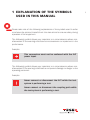
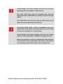
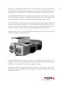
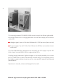
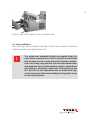
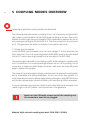
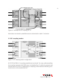
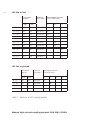
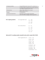
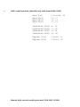
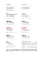
1
manual high-Current
coupling/decoupling
network CDN 3083-S200N
User Manual
601-332A
manual high-Current
coupling/decoupling
network CDN 3083-S200N
User Manual
Manual high-current coupling network CDN 3083–S200N
contentS
1. Explanation of the symbols used in this manual
2. Safety advice
2.1 Safety measures
2.2 Installation
2.3 Installation of an equipment under test power switch
2.3.1 Applicable safety standards
2.3.2 Leakage current
3. Applications
4. Assembling of test rig and the CDN sub-units
4.1 Installation of a test rig
4.2 Preparation of the CDN 3083
4.2.1 Mounting of the common earth bars
4.2.2 Mounting positioning plates
4.2.3 Assembly for IEC coupling
4.2.4 Assembly for ANSI coupling 4.3 EUT connections
4.3.1 EUT power feed
4.4 Test conditions
5. Coupling modes overview
5.1 Phase synchronisation
5.2 IEC coupling modes
5.3 ANSI coupling mode
6. Effects on the EUT
7. Maintenance
8. Technical specifications CDN 3083-S200N
9. Warranty
10. Addresses
5
7
8
8
10
10
11
12
15
15
17
17
18
20
21
22
22
23
24
24
25
28
32
33
34
37
38
1 explanation of the symbols
used in this manual
Please take note of the following explanations of the symbols used in order
to achieve the optimum benefit from this manual and to ensure safety during
operation of the equipment.
The following symbol draws your attention to a circumstance where nonobservation of the warning could lead to inconvenience or impairment in the
performance.
Example:
This connection must not be confused with the EUT
power input.
The following symbol draws your attention to a circumstance where nonobservation of the warning could lead to component damage or danger to the
operating personnel.
Example:
Never connect or disconnect the EUT while the test
system is performing a test.
Never connect or disconnect the coupling path while
the test system is performing a test.
5
6
Lethal danger from high voltages and the risk of radiating illegal electromagnetic interference.
The CDN 3083 may only be installed and used by
authorised and trained EMC specialists (electrical engineers).
The CDN 3083 must only be used for EMC tests as set
down in these operating instructions.
Personnel fitted with a heart pacemaker must not
operate the instrument and must not be in the vicinity
of the test rig while it is in operation.
Lethal danger from high voltages and the risk of high
levels of electromagnetic radiation being generated.
When the system is used in conjunction with options,
accessories or other equipment the safety instructions
concerning those devices must also be observed.
Manual high-current coupling network CDN 3083–S200N
2safety advice
Improper or careless handling can be fatal! The instrument must only be used by trained personnel.
These operating instructions form an integral part of the equipment and must
be studied carefully before putting the device into use. It needs to be available
to the operating personnel at all times. All the safety instructions and advice
notes are to be observed.
Keeping responsibility to the instructions and recommendations that follow is
imperative.
The safety advice referring to the generators also applies and must be followed
when using the instruments together with the CDN 3083.
Neither Teseq AG, Switzerland nor any of the associated sales organizations
accept any responsibility for personal injury or for material or consequential
damage that may results through irresponsible or negligent operation of this
equipment.
When used with a generator NSG 3040 or Modula the
EUT input voltage is limited to max. 440 Vrms line to line
and 400 Vrms line to ground. If this level is exceeded
the generator might be damaged.
When use with generator NSG 3060 and for EUT voltage
< 440 Vrms do not set pulse repetition rate >20 seconds.
The NSG 3060 may be damaged if this is not respected.
7
8
2.1. Safety measures
Persons fitted with a heart pacemaker must not operate the instrument and
should not be in the vicinity of the test rig when pulses are generated.
The test rig must provide adequate insulation protection for up to 5 kV surge.
Particular care should be given to the connections between the CDN 3083 and
the equipment under test (EUT).
The EUT may only be tested when placed inside a suitable protective enclosure which should provide protection against flying fragments, fire and electric
shock.
The pulse voltage must not be able to find its way to unearthed metal objects
in the event of the EUT failing.
Only use the instrument in a dry room.
Never leave the instrument unattended when the EUT is switched on.
Regularly check the heat of the CDN using the built in thermometer and switch
EUT off if the temperature exceeds 70°C.
Do not open the instrument. Repairs and adjustments must only be carried out
by qualified maintenance personnel.
Do not continue to use the CDN in case of any mechanical damage occur. The
CDNs housing and the cables have both insulating and screening function,
which can only be assured while the housing is intact. Return the damaged
CDN to a Teseq service centre immediately for repair.
2.2 Installation
The test system conforms to protection class 1. Local installation regulations
must be respected to ensure the safe flow of leakage currents.
Manual high-current coupling network CDN 3083–S200N
Operation without a protective earth connection is forbidden! Therefore it is imperative to screw both earth
copper rails to the CDN.
Switch off EUT power before accessing EUT power «in»
or «out» terminals. Use the insulated allen key always
when working on the terminals.
It is recommended to connect the CDN 3083-S200N
through a properly rated power switch device, which
should be located close to the test setup. In order to
ensure an easy and quick acces to the EUT power, same
should be clearly and visibly labelled as a device for
«EUT power on/off» switching.
The inhouse power distribution needs to be equipped
with a proper circuit breaker and an emergency off
button as per IEC 61010-1:2001.
Two independent protective earth connections are necessary (for the test
system and the EUT). These must be connected back to the local permanent
installation or to a fixed, permanent protective earth conductor.
Operate the equipment only in dry surroundings. Any condensation that occurs
must be allowed to evaporate before putting the equipment into operation. Do
not exceed the permissible ambient temperature or humidity levels. Use only
officially approved connectors and accessory items.
9
10
2.3 Installation of an equipment under test power switch
It is recommended to connect the CDN through a properly rated power switch
device, which should be located close to the test setup. In order to ensure an
easy and quick access to the equipment under test (EUT) power, same should
be clearly and visibly labelled as a device for «EUT power on/off» switching.
The in-house power distribution needs to be equipped with a proper circuit
breaker and an emergency off button as per IEC/EN 61010-1:2001.
The test setup should only be accessible to trained personal.
Dimensioning of mains supply and rating of fuse protection of AC or DC power
supply must conform with national prescriptions and EUT requirements.
Inappropriate arrangement, mounting, cabling or handling of the device under
test or the protective elements can make the protective features that are incorporated in the concept of the instrument worthless.
2.3.1 Applicable safety standards
Development and manufacture is in compliance with ISO 9001.
The instrument complies with the safety requirements of IEC/EN 61010-1 (safety
requirements of electrical equipment for measurement, control and laboratory
use).
The interference immunity has been tested in accordance with EN 61326-1.
It is the user’s responsibility to ensure that the test rig does not emit excessive electromagnetic interference (EMI) that might affect other items. The test
system itself does not produce any excessive radiation; however, the injection
of interference pulses into the EUT can result in the device and/or its associated
cables starting to radiate EMI. To avoid radiating unwanted interference into
the environment, the standards organisations recommend that the test rig be
operated in a Faraday cage.
Manual high-current coupling network CDN 3083–S200N
2.3.2 Leakage current
CDN 3083-S200N generates high leakage currents to ground, by specification.
There for the EUT power supply connection needs to be free of differential
circuit breaker protection.
Local installation regulations must be respected to ensure the safe flow of
leakage currents.
Always first connect the PE wire to CDN 3083-S200N.
Use only nationally approved connectors and accessory items.
Ensure that a reliable return path for the interference current is provided
between the EUT and the coupling/decoupling network.
11
12
3applications
The manual coupling network CDN 3083 fulfils the requirements called for in the
surge standard IEC/EN 61000-4-5, including the new features concerning high
currents as well as in the ANSI C62.45 and other relevant standards.
The form of construction selected suits the demands placed on the instrument
in its working environment. In its basic form, the coupler is made for use on a
floor or for table top placement in an EMC laboratory or in a development workshop. It can be even mounted onto the wall to have free space on test bench.
High-current couplers may need to be taken to test sites where it is commonly
impossible to move large installations in. For convenience, the CDN 3083 can
be disassembled in handy parts and can easily move to other places. Optional
wheels with braking features can be mounted.
Injecting surge pulses into power connections always involves a careful weighing up of partially conflicting requirements. On the one hand the power network
has to be protected from the interference signals while the effects of the pulses
are concentrated on the equipment under test, yet on the other hand the back
filter must not result in any significant voltage drop.
In order to keep voltage losses within reasonable limits with increasing current
levels, the IEC has defined three classes of filter inductances, namely: up to
25 A, 25 to 60 A and 60 to 100 A.
Note: Classic high-current couplers cannot be used any longer for
lower current levels since the filtering effect is insufficient.
Further construction features make the application of the unit even more universal.
The nominal maximum current rating of 200 A per phase can, during short test
Manual high-current coupling network CDN 3083–S200N
periods, be considerably exceeded. The unit will tolerate the frequently encountered inrush currents without complaint and, in extreme cases it can be overstressed until the internal environment has reached the max. temperature of 70°C.
The CDN 3083-S200N is hence usable where otherwise a CDN for more than
200 A would be necessary. For single phase application even much more then
200 A per phase is possible by paralleling 2 decoupling network paths.
CDN 3083-S200N is delivered with external fans mounted. Supply cables for
the fans are part of the delivery. It is recommended to supply the fans with 110
VAC when the CDN 3083-S200N is used in the upper load range (Example: EUT
current >100 A), or when environmental temperature is high (>30° C).
When fans are used, the CDN 3083-S200 can easily carry out EUT currents up
to 230 A/channel, this permanently.
The CDN 3083-S200N is tested for safety in compliance with IEC 61010. The
rugged connection terminals together with the solid earth line assure a proper
connection, this in combination with a rugged housing.
Protection covers for unused terminals are part of the delivery. When EUT
power or pulses are applied, always cover the unused terminals with these
protection covers.
13
14
The coupling network CDN 3083-S200N serves to inject the following standardized surge pulses from the surge generator into the mains supply to the device
under test:
Voltage surge of up to 4.4 kV which follows the 1.2/50 µs curve (open-circuit)
Current surge of up to 2.2 kA which follows the 8/20 µs curve (short circuit
conditions)
The CDN 3083-S200N is designed to be used with an EUT supply of up to 440
Vrms line to line and 400 Vrms line to ground at 200 A.
Coupling surge pulses with higher voltages is in principle possible, but in case
the EUT draws low currents the backfilter chokes may go in saturation due to
the higher surge kickback currents and no more provide a good backfiltering
performance.
Operation is manual, simple and designed to be safe.
Manual high-current coupling network CDN 3083–S200N
4 assembling of test rig and the
cdn sub-units
The CDN 3083-S200N contains following parts:
1 Surge decoupling network CDN 3083-S200 N – L1
1 Surge decoupling network CDN 3083-S200 L2 – L3
2 Earth rails
1 Allen key, isolated 1 User manual CDN 3083-S200N
1 Traceable calibration certificate
8 Terminal safety covers
2 INA 3080 Surge coupling unit
1 Connection cable 0.5 m Fischer/Fischer connector
1 INA 3084 Synchronisation unit for NSG 3040 or Modula
2 x Cable 1 m, with each a Fischer/Fischer connector
Screw set
8 wheels with brakes
4.1 Installation of a test rig
This section describes the check-up and installation of the CDN 3083 coupling
network after delivery as well as providing a check on the functions of the unit
after being transported or following to significant changes within the test rig.
Installation should only be carried out by experienced personnel.
a) Check the delivery for completeness.
b) Check the unit for any signs of damage in transit. Report any damage found
to the carrier immediately.
c) Study the manual.
d) Set up the surge generator in accordance with the instructions in its manual
but do not, however, switch the instrument on.
e) For convenience, place the coupling network close to the generator.
f) Connect the protective earth to the terminal. The same protective earth
should also be connected to the earth terminal of the generator.
15
16
g)
h)
i)
j)
k)
l)
Plug the high voltage connectors into the surge generator.
Connect the INA 3084 synchronisation unit to the generator.
Connect the EUT supply.
Switch on the mains power at the generator.
Choose the appropriate coupling mode.
Connect the device to be tested according to the relevant safety specifications and with due regard to the magnitude of the pulse voltage selected.
Take the necessary measures to cope with any possible explosion or
outbreak of fire.
m) Switch on the EUT power supply.
n) Operate the generator as instructed in its manual and carry out the required
tests.
It is assumed that the test rig has been set up in accordance with the foregoing
notes and that the device to be tested has been connected taking the relevant
safety measures into account.
Manual high-current coupling network CDN 3083–S200N
4.2 Preparation of the CDN 3083
Prepare the test setup conform to the chosen standard and put both decoupling
network units, etc. to the place where the CDN shall be used for testing.
4.2.1 Mounting of the common earth rails
Place the two surge decoupling networks in parallel to each other. Looking from
the top, make sure that the N-L1 network is below the L2-L3 network.
To enable proper synchronisation, assure that side L1
being placed next to L2!
Use the delivered isolated allen key to screw the copper earth rails on to both
ends of the decoupling networks (2 x 2 screws each side per network).
Make sure that the copper rail is properly mounted and
tightened. Use only the delivered screws.
17
18
2x
2x
M8 x 16 mm
M8 x 16 mm
2x
2x
M8 x 16 mm
M8 x 16 mm
Figure 1: Top view on CDN units
Photo 1: Assembly of copper earth rail
After this preparation work, the CDN is stable enough for being turned to its side
prior to mounting the wheels at the bottom of the case, if required.
4.2.2 Mounting positioning plates
Screw the base plates (positioning plates) of the synch unit and of the coupling unit, with the knurled screws to the foreseen holes on the outside of the
decoupling networks. Connect the synch lines (safety banana connector) to the
decoupling units. If CDN 3083 decoupling networks are not placed correctly,
the positioning plates can not be screwed on.
Manual high-current coupling network CDN 3083–S200N
19
Figure 2: Location of synchronisation unit and of positioning plate
Photo 2: Synchronisation plate (l.h.) and positioning plate (r.h.)
20
4.2.3 Assembly for IEC coupling
For IEC coupling, add the coupling modules INA 3080 in the middle of the
positioning plate and press it slightly down into the positioning holes. Fix the
INA by pushing the black quick snap-on knobs down. The CDN 3083 is now
ready to use.
Figure 3: Location of IEC coupling module
Photo 3: View of IEC coupling module
Manual high-current coupling network CDN 3083–S200N
4.2.4 Assembly for ANSI coupling
For ANSI coupling, add both coupling units INA 3080 on the positioning plate
and press it slightly down into the positioning holes. Fix the INAs by pushing
the black quick snap-on knobs down. The CDN 3083 is now ready to use.
Figure 4: Location of ANSI coupling modules or additional IEC coupling mode
Photo 4: View of ANSI coupling modules
Because of the coupling capacitors, the mains voltage can
be present at the HV connectors when the EUT power
supply is switched on. The HV connectors must therefore
always be hooked up to the generator before the mains
and the EUT power supply are switched on.
21
22
4.3 EUT connections
The CDN 3083 is equipped with EUT terminals suitable for a max. wire gauge of
110 mm2 AWG 4-4/0 (230 A), torque: max. 20 Nm.
The in-house power distribution needs to be equipped
with a proper circuit breaker and an emergency off button
as per IEC/EN 61010-1:2001.
4.3.1 EUT power feed
The power is fed in via 5-core cable leads.
Do not mismatch the EUT power input of the CDN and the
EUT power output. Use only the delivered isolated allen
key to screw the cables to the terminals. Never touch the
terminals during the EUT power is on.
EUT power input
EUT power output
Figure 5: Identification of EUT power input and output
Manual high-current coupling network CDN 3083–S200N
23
Photo 5: View of EUT power input connection side
4.4 Test conditions
Every test rig must be planned carefully. All the instrumentation should be
readily accessible and rigidly positioned.
The whole test assembly should be supplied from the
same mains connection in order to prevent uncontrolled
flow of pulse current in other parts of the system. Installation in a Faraday cage ensures that non-associated items
and equipment are not disrupted by pulses radiatedfrom
the cabling or the device under test. Connections to the
EUT must be of low impedance and be made with high
contact pressure. Otherwise weldingor arcing might occur
at the contact points.
24
5coupling modes overview
Following all possible coupling modes are described.
The following example shows a coupling from L3 to N whereby the generator
High output is connected to the INA 3080 surge coupling unit input. One end is
looped, in order to get the recommended 18 μF capacitance required for line to
line coupling according to IEC/EN 61000-4-5. The other pulsed end is connected
to L3. The generator low output is directly connected to the N line.
5.1 Phase synchronisation
In the INA 3084 synchronisation unit the input voltage L1 to N is wired out for
Sync reference. The ca. 2 meter long cable of INA 3084 needs to be connected
to the EUT mains input plug located on the rear side of the NSG 3040.
The phase angle indicated on the display of NSG 3040 is always in relation with
the L1-N reference. For coupling settings different from L1 to N coupling, it is up
to the user to make the phase angle correction, and enter the required phase
angle + phase shifting value.
The value of the phase angle shifting in relation with the selected coupling path
and is installation and wiring dependent. At first use of the test system it is
recommended to make the phase angle setting verification using MD 200 Probe
and to edit a phase angle correction table to be used during further operation.
For synchronisation purpose the cable end of the INA 3084 synchronisation unit
needs to go to the EUT power input connection of the generator.
Never run the CDN with a loose end of the coupling unit.
All connectors need to be plugged.
Manual high-current coupling network CDN 3083–S200N
25
Figure 6: Example of IEC coupling L3- N
Alternative connection possibilities are summarized in table 1 hereafter.
5.2 IEC coupling modes
Figure 7:IEC coupling basic configuration
All IEC/EN 61000-4-5 coupling possibilities are listed. For easy understanding,
the coupling network INA 3080 input is identified by X1 while the outputs are
marked with X2 and X3. Depending on coupling mode selected following connections are to be established for:
26
IEC line to line
Generator
output
Loop on
INA 3080
Decoupling network
CDN 3083-S200
High
Low
L1
L2
L3
L1 – N
X1
N
X2 to X3
X3
L1 – L2
X1
L2
X2 to X3
X3
L1 – L3
X1
L3
X2 to X3
X3
L2 – N
X1
N
X3 to X2
X2
L2 – L1
X1
L1
X3 to X2
X2
L2 – L3
X1
L3
X3 to X2
X2
L3 – N
X1
N
X3 to X2
X2
L3 – L1
X1
L1
X3 to X2
X2
L3 – L2
X1
L2
X3 to X2
X2
IEC line to ground
Generator
output
Loop on
INA 3080
High
Low
N – PE
X1
PE
X2 to X2
L1 – PE
X1
PE
X2 to X2
L2 – PE
X1
PE
X3 to X3
L3 – PE
X1
PE
X3 to X3
Decoupling network
CDN 3083-S200
N
L1
L2
L3
X3
X3
X2
X2
Table 1: Selection of IEC coupling modes
Manual high-current coupling network CDN 3083–S200N
27
Photo 6: IEC coupling L1-N
Photo 7: IEC coupling L2-N
Photo 8: IEC coupling L2-PE
28
Photo 9: IEC coupling L1-PE
INA 3084 / 3085
Synchronisation Unit
5.3 ANSI coupling mode
For coupling modes required by ANSI standard, a second INA 3080 needs to
be added on the CDN 3083.
Figure 8: ANSI coupling basic configuration
Manual high-current coupling network CDN 3083–S200N
ANSI coupling
29
Generator
output
Loop on
INA 3080
Connection
from X1 to Y1
Decoupling network
CDN 3083-S200
High
Low
Basic 1
X1
PE
––
Yes
Basic 2
X1
L1
X2 to X3
No
Basic 3
X1
L2
X2 to X3
No
Basic 4
X1
L3
Y3 to Y2
No
Supplemental 1
X1
PE
Y2 to Y3
No
Supplemental 2
X1
PE
Y3 to Y2
No
Supplemental 3
X1
PE
X2 to X3
No
Supplemental 4
X1
PE
X3 to X2
No
Diagnostic 1
X1
N
Y3 to Y3
Yes
Y2
X3
X2
Diagnostic 2
X1
PE
Y3 to Y3
Yes
Y2
X3
X2
Table 2: Selection of ANSI coupling modes
Photo 10: ANSI coupling basic 1
N
L1
L2
L3
Y3
Y2
X3
X2
X3
X2
Y2
Y3
Y2
X3
X2
Basic 1
30
Low
High
Basic 2
Low
High
Basic 3
Low
High
Basic 4
Low
High
L1
L2
L3
N
PE
Supplemental 1
Low
High
Supplemental 2 Supplemental 3
Low
High
Low
High
Supplemental 4
Low
L1
L2
L3
N
PE
Manual high-current coupling network CDN 3083–S200N
High
Diagnostic 1
Diagnostic 2
Low
Low
High
High
L1
L2
L3
N
PE
The following example shows diagnostic 1 ANSI coupling.
Photo 11: ANSI coupling diagnostic 1
31
32
6Effects on the eut
The surge pulse contains considerable energy. When super-imposed on the
mains, a significant resultant current can occur if the EUT becomes defective.
The effects can be very different, depending on the characteristics of the equipment undergoing the test:
No effect
Brief faulty operation without permanent damage
Reduction of the insulation resistance or similar
Quality affected (life expectancy)
Change in the technical specification of the device under test
Flash-over in cables, connectors and equipment
Bursting of components
Explosion of components
Burning of parts caused principally by resultant mains current when mains
superposition mode is used
Damage to equipment, systems or components that are electrically or
inductively coupled to the pulse current path
When testing with high energy surge pulses, a test on
a device should never be considered as being damagefree until a subsequent thorough investigation proves
that the EUT is still fully intact.
Manual high-current coupling network CDN 3083–S200N
7Maintenance
Basically there is no need of maintenance and the CDN 3083-S200N does not
contain serviceable parts. The housing may be cleaned with a moist cloth with
possibly just a trace of detergent liquid. Industrial spirit is also a suitable cleaning
agent. Other solvents are not permitted.
Only specialist or trained maintenance personnel may carry out internal work
on the instrument. In the event of more service or repair work being necessary,
the instrument should be returned to a Teseq service center accompanied by
an appropriate description of the problem. The instrument contains no fuses.
33
34
8Technical specifications
CDN 3083–S200N
The CDN 3083 is a 3-phase manual coupling network for surge interference
pulses as per IEC/EN 61000-4-5 and ANSI C62.45 and other related standards.
The CDN 3083-S200N base
1 Surge decoupling network
set is consisting of:
CDN 3083-S200N – L1
1 Surge decoupling network
CDN 3083-S200N L2 – L3
2 Earth rails
1 Wheel set
1 Allen key, isolated
1 User manual CDN 3083 S200N
1 Test certificate
2 INA 3080 Surge coupling unit
1 Connection cable
1 INA 3084 Synchronisation unit for
NSG 3040
2 x Cable 1 m, with each a Fischer/Fischer
plug
Pulse voltages/current:
4.4 kV/2.2 kA max.
EUT power supply voltage:
440 Vrms line-to-line
400 Vrms line-to-ground
500 VDC, max.
Current:
200 Arms or DC max. per line
Frequency:
DC to 60 Hz (400 Hz max. with increased
power loss)
EUT connection:
Screw-terminals, 230 A, up to 110 mm2
(AWG 4-4/0)
Max. temperature:
70°C
Manual high-current coupling network CDN 3083–S200N
Coupling modes:
Dimensions:
Weight:
Optional accessories:
Surge differential, lines to PE, common to
PE (with ANSI coupling set or with optional
INA 3080 coupling unit for IEC)
850 x 520 x 345 (L x D x H) mm
(33.5 x 20.5 x 13.6”)
80 kg approx.
MD 300 Current measuring probe
MD 200/200A Voltage measuring probe
IEC coupling modes:
Line to ground (9 μF)
L1 — PE
L2 — PE
L3 — PE
N — PE
Line to line (18 μF)
L1 — N
L1 — L2
L1 — L3
L2 — N
L2 — L3
L3 — N
Optional IEC coupling modes (possible only with second INA 3080):
Lines to ground (9 μF)
L1+L2 — PE
L1+L3 — PE
L1+N — PE
L2+L3 — PE
L2+N — PE
L3+ N — PE
L1+L2+L3 — PE
L1+L2+N — PE
L1+L3+N — PE
L2+L3+N — PE
L1+L2+L3+N — PE
35
36
ANSI coupling modes (possible only with second INA 3080):
Basic 1 (9 μF) Basic 2 (18 μF)
Basic 3 (18 μF)
Basic 4 (18 μF)
L1+L2+L3+N — PE
L2 — L1
L3 — L2
L1 — L3
Supplemental 1 (18 μF) Supplemental 2 (18 μF) Supplemental 3 (18 μF)
Supplemental 4 (18 μF)
N — PE
L1 — PE
L2— PE
L3 — PE
Diagnostic 1 (9 μF) Diagnostic 2 (9 μF)
L1+L2+L3 — N
L1+L2+L3 — PE
Manual high-current coupling network CDN 3083–S200N
9Warranty
Teseq grants a guarantee of 2 years on this instrument, effective from the date
of delivery.
During this period, any defective component/part will be repaired or replaced
free of charge or, if necessary, the instrument will be replaced by another of
equivalent value. The decision regarding the method of reinstating the functional capability is at the sole discretion of Teseq.
Excluded from the guarantee are damages or consequential damages caused
through negligent operation or use as well as the replacement of parts subject
to degradation.
The guarantee is rendered invalid by any intervention by the customer or a
third party.
The goods are to be returned in the original packing or other equivalent packing
suitable for the purpose of the foreseen means of transport. Teseq shall accept
no responsibility for damage in transit.
37
Headquarters
Teseq AG
4542 Luterbach, Switzerland
T + 41 32 681 40 40
F + 41 32 681 40 48
sales @ teseq.com
www.teseq.com
Manufacturer
Teseq AG
4542 Luterbach, Switzerland
T + 41 32 681 40 40
F + 41 32 681 40 48
sales @ teseq.com
China
Teseq Company Limited
T + 86 10 8460 8080
F + 86 10 8460 8078
chinasales @ teseq.com
France
Teseq Sarl
T + 33 1 39 47 42 21
F + 33 1 39 47 40 92
francesales @ teseq.com
Germany
Teseq GmbH
T + 49 30 5659 8835
F + 49 30 5659 8834
desales @ teseq.com
Japan
Teseq K.K.
T + 81 3 5725 9460
F + 81 3 5725 9461
japansales @t eseq.com
Singapore
Teseq Pte Ltd.
T + 65 6846 2488
F + 65 6841 4282
singaporesales @ teseq.com
Switzerland
Teseq AG
T + 41 32 681 40 50
F + 41 32 681 40 48
sales @ teseq.com
Taiwan
Teseq Ltd.
T + 886 2 2917 8080
F + 886 2 2917 2626
taiwansales @ teseq.com
UK
Teseq Ltd.
T + 44 845 074 0660
F + 44 845 074 0656
uksales @ teseq.com
USA
Teseq Inc.
T + 1 732 417 0501
F + 1 732 417 0511
Toll free +1 888 417 0501
usasales @ teseq.com
© March 2010 Teseq®
Specifications subject to change
without notice. Teseq® is an ISOregistered company. Its products are
designed and manufactured under
the strict quality and environmental
requirements of the ISO 9001. This
To find your local partner within document has been carefully checked.
Teseq®’s global network, please go to However, Teseq® does not assume
www.teseq.com
any liability for errors or inaccuracies.