1
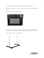
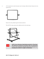
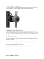
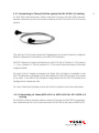
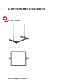
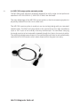
®
E stablished 1981
Advanced Test Equipment Rentals
www.atecorp.com 800-404-ATEC (2832)
1
INA 703
Magnetic field coil
User manual
601-335A
INA 703
Magnetic field coil
User manual
INA 703 Magnetic field coil
contents
1
2
2.1
2.2 2.3 2.4 3
3.1
3.2 3.3 3.4 3.4.1
3.4.2
3.4.3
3.4.4
3.4.5
3.5 4
4.1 4.2 4.3 4.4 4.5 5
6
6.1 6.2 6.3 6.4 6.5 6.6 7
8
Explanation of symbols
Introduction General description Supply frequency magnetic fields
Pulsed magnetic fields
Oscillatory magnetic fields
User instructions General
Unpacking and installation
Positioning
Connection to the generator
Connecting to Teseq ProfLine system for IEC 61000-4-8 testing
Connecting to Teseq MFO 6501 or MFO 6502 for IEC 61000-4-8
testing
Connecting to any other generator for IEC 61000-4-8 testing
Connecting to Teseq NSG 3040 or NSG 3060 for IEC 61000-4-9
testing
Connecting to Teseq NSG 3040 or NSG 3060 for IEC 61000-4-10
testing
Test execution Maintenance and function check General
Cleaning
Function check Calibration Warranty Declaration of conformity (CE) Options and accessories INA 703 Stand
INA 703 Coil
INA 3250 interconnection cable
INA 3251 Interconnection cable
Pulse wave shape adapter INA 752 MD 300 surge pulse current probe set System description
Addresses 5
6
6
7
8
9
10
10
10
13
14
15
15
16
17
17
17
19
19
19
19
20
20
21
22
22
22
23
23
23
24
25
26
Lethal danger from high voltages and the risk of radiating illegal electromagnetic interference.
This system must be used only for EMC test purposes
as specified in these operating instructions.
The INA 703 must be installed and used only by authorized and trained EMC specialists.
Personnel fitted with a heart pacemaker may not
operate the instrument and must not be in the vicinity
of the test setup while it is in operation.
When the system is used in conjunction with options,
accessories or other equipment the safety instructions
concerning those devices must also be observed.
1Explanation of symbols
Please take note of the following explanations of the symbols used in order
to achieve the optimum benefit from this manual and to ensure safety during
operation of the equipment.
The following symbol draws your attention to a circumstance where nonobservation of the warning could lead to inconvenience or impairment in the
performance.
Example:
This connection must not be confused with the Equipment under Test (EUT) power input.
The following symbol draws your attention to a circumstance where nonobservation of the warning could lead to component damage or danger to the
operating personnel.
Example:
Never connect or disconnect the EUT while the test
system is performing a test.
5
6
2Introduction
2.1 General description
INA 703 is the top end of a family of magnetic field coils, designed for testing per
IEC 61000-4-8 (supply frequency magnetic fields) , IEC 61000-4-9 (pulsed magnetic
fields), IEC 61000-4-10 (oscillatory magnetic fields).
Thanks to a multi wire - 37 turns – concept , it allows the generation of fields higher
than 1000 A/m while using a current source rated for 30 A, so insures the possibility
to meet the IEC 61000-4-8 standards requirement of a current THD < 8% which can
be met only when using a synthetic current source.
INA 703 has a connection possibility after wire turn 1 and turn 5, which allows to
reach great accuracy when generating low amplitude fields.
INA 703 Magnetic field coil
The tap off after 1 turn is also used for tests per IEC 61000-4-9 and IEC 61000-4-10,
which both require a single turn coil.
For tests per IEC 61000-4-8, INA 703 can be used as an accessory to the Teseq
profline system, together with a NSG 1007- 5 kVA source, the INA 2141 impedance
box and the WIN 2120 software can generate supply frequency fields (50 and
60 Hz) up to 330 A/m continuously and 1100 A/m short term (3 s).
It can also be used with the MFO 6501 or 6502 current sources and the NSG 3000
series of generators and generate Supply frequency fields (50 and 60 Hz) up to
120 A/m continuously and 120 A/m short term (3 s).
For tests per IEC 61000-4-9, INA 703 can be used together with a classic combined
wave generator as available in NSG 3040 or NSG 3060 series plus a pulse wave
shape adaptor box INA 752.
For tests per IEC 61000-4-10, INA 703 can be connected to an adequate slow oscillatory waves generator.
Thanks to the multi wire concept and to the professional mechanical design, like U
shape base on rolls which allows convenient approach and positioning to the test
table, INA 703 is the ideal accessory for magnetic field testing.
2.2 Supply frequency magnetic fields
Supply frequency magnetic field tests, simulate the magnetic fields typically generated by the current flow in power supply cables as specified in IEC/EN 61000-4-8.
Such magnetic fields can affect the operation of items of equipment that are sensitive to them.
For testing to IEC 61000-4-8, the INA 703 needs to be supplied by a regulated 50 or
60 Hz current (THD<8%) of maximum 10 A continuously and 35 A short term (<5 s).
Single turn, 5 turns , and 37 turns can be selected in order to reach high fields with
low currents, but maintaining good resolution for lower fields testing.
7
8
The Teseq ProfLine system comprising an NSG 1007- 5 kVA source, an INA 2141
impedance box and WIN 2120 software is ideally suited for this application. For this
setup the interconnection cable INA 3250 is required.
The system can generate supply frequency fields (50 and 60 Hz) up to 330 A/m
continuously and 1100 A/m short term (3 s).
For more information please consult ProflLne 2100 series user documentation.
The INA 703 can also be used with the Teseq MFO 6501 or 6502 current sources
and the NSG 3000 series of generators to generate supply frequency fields (50 and
60 Hz) up to 120 A/m continuously and 120 A/m short term (3 s). For this setup the
interconnection cable INA 3251 is required.
For more information please consult MFO 6501/2 or NSG 3040 series user manuals.
2.3 Pulsed magnetic field
Pulsed magnetic fields tests, simulate the type of interference produced by surge
pulses as a result of lightning strikes to buildings or other metallic structures such
as free standing masts, ground conductors, grounding networks, etc. as specified
in IEC/EN 61000-4-9. Magnetic fields of this type can upset the operation of installations that find themselves within such fields.
For testing to IEC 61000-4-9, the INA 703 can be used together with a classic combination wave generator such as the NSG 3040 or NSG 3060 series.
For this test a single loop ( 1 turn) will be used.
In order to meet the pulse waveform required by IEC 61000-4-9, the waveshape
adapter INA 752 needs to be used.
INA 703 Magnetic field coil
2.4 Oscillatory magnetic fields
Oscillatory magnetic fields tests, simulate the type of interference produced by the
switching of medium and high voltage switchgears, as specified in IEC/EN 610004-10.
Magnetic fields of this type can upset the operation of installations that find themselves within such fields.
For testing to IEC 61000-4-10, the INA 703 can be connected to an appropriate slow
oscillatory wave generator.
For this test a single loop (1 turn) will be used.
9
10
3 User instructions
WARNING - Improper or careless operation can be fatal!
These operating instructions form an essential part of the equipment and must be available to the operator at all times. The user
must obey all safety instructions and warnings.
Neither Teseq AG, Luterbach, Switzerland, nor any of its subsidiary
sales organisations can accept any liability for personal, material or consequential injury, loss or damage that may result from
improper use of equipment and accessories.
3.1 General
The INA 703 together with the adequate generator must be operated only by
authorized and trained specialists. The generator with the coil is to be used only
for the purpose specified by the manufacturer. The user is directly responsible for
ensuring that the test setup does not cause excessive radiated interference which
could affect other instrumentation or human beings. The test system itself does
produce EM radiation up to 1100 A/m .
WARNING - Personnel fitted with a heart pacemaker must
neither operate the instrument nor approach the test
setup while a test is being executed.
Only approved accessories, connectors, adapters, etc. are to be used to ensure
safe operation.
3.2 Unpacking and installation
Check the packaging for signs of damage in transit. Any damage should be reported
immediately to the transportation company.
INA 703 Magnetic field coil
INA 703 is delivered dismantled, safely packed in a solid wooden box.
Identify the upper side of the box and remove cover after having removed the
screws.
The contents of the package will look like:
Unpack carefully the various parts. Check the parts for signs of transport damage.
Any damage should be reported to the transportation company immediately.
Screw the vertical bars to the rolling base.
11
12
Lift (2 persons) the coil (red part) over the base, slide the black fixtures into the
vertical bars.
Secure the coil by fastening the fixtures to the bar.
The INA 703 is now ready to be rolled around to the test setup.
NOTE! Do not dispose of packaging materials. All packaging should be retained in the event that the instrument
or any of its accessories should need to be returned to a
Teseq service center for repair or calibration.
INA 703 Magnetic field coil
3.3 Positioning
The U-shaped base with castors will allow easy positioning of the INA 703 to the
EUT, even if this one is placed on a test table.
The equipment to be tested shall always be positioned in the geometric center of
the red coil part
Tests need to be done with the coil in horizontal position and then in vertical position, 2 bubble level indicators as shown in picture below will facilitate the right
positioning.
Bubble level indicators
Securing in horizontal and vertical position goes easy thank to the positioning lock:
Position lock
NOTE! Standards require only testing for horizontal or vertical position. INA 703 positioning lock has an intermediate position at 45 ° which may be used for investigation
purposes.
13
14
3.4 Connection to the generator
The INA 703 features a multipole terminal system which insures comfortable and
safe connection of various generators suited for various applications
Safety banana plugs: Red and black
These 2 plugs are mainly used for pulsed and oscillatory magnetic fields testing. The
Black banana is the low entry of the coil, the red banana is connected to the end of
Turn Nr 1. connecting to these terminals is equivalent to test with a single turn coil.
Round 4 pole connector:
The pole marked with PE sign is connected together with the black banana to the
low entry of the coil.
Pole Nr. 1 is connected together with the red banana to the end of turn Nr. 1
Pole Nr. 2 is connected to the end of turn Nr. 5
Pole Nr. 3 is connected to the end of turn Nr. 37
INA 703 Magnetic field coil
3.4.1 Connecting to Teseq ProfLine system for IEC 61000-4-8 testing
An INA 3250 interconnection cable is required. Connect the INA 3250 interconnection cable directly from the 4 pole connector of INA 703 to INA 2141 of ProfLine
system.
The setting of the various levels and frequencies of supply frequency magnetic
fields is supported comfortably by the WIN 2120 software.
INA 2141 features 3 ranges (red selector on INA 2141 front: Position 0= Off, position
1 = 1 turn, position 2= 5 turns, position 3 = 37 turns) for better accuracy of low level
magnetic fields.
For each of the 3 ranges a separate coil factor (the coil factor is available in the
INA 703 calibration certificate and is also labelled on INA 703 terminal unit) needs
to be used. In the WIN 2120 software configuration file the INA 703 needs to be
configured as 3 separate coils.
For more information please consult the ProfLine systems user documentation.
3.4.2 Connecting to Teseq MFO 6501 or MFO 6502 for IEC 61000-4-8
testing
An INA 3251 interconnection cable is required. Connect the INA 3251 interconnection cable directly from the 4 pole connector of INA 703 to the output of MFO 6501.
15
16
The 3 ranges of the INA 703 are selectable by a respective banana plug (Green/
yellow = Low, blue = 1 Turn, Black = 5 Turns, red = 37 Turns) for better accuracy of
low level magnetic fields.
For each of the 3 ranges a separate coil factor. (The coil factor is available in the
INA 703 calibration certificate and is also labelled on INA 703 terminal unit) needs
to be used.
For more information please consult the NSG 3040 systems or MFO 6501/2 user
documentation.
3.4.3 Connecting to any other generator for IEC 61000-4-8 testing
An INA 3251 interconnection cable is required. Connect the INA 3251 interconnection cable directly from the 4 pole connector of INA 703 to the output of the
generator.
The 3 ranges of the INA 703 are selectable by a respective banana plug (Green/
yellow = Low, blue = 1 Turn, Black = 5 Turns, red = 37 Turns) for better accuracy of
low level magnetic fields.
For each of the 3 ranges a separate coil factor. (The coil factor is available in the
INA 703 calibration certificate and is also labelled on INA 703 terminal unit) needs
to be used.
Make sure that the maximum ratings of INA 703 are not
exceeded – risk of fire.
For Standard compliance testing the generator shall have
a THD<8%, this is not permanently guaranteed when
solutions based on variacs and step down transformers
powered from mains supply are used.
INA 703 Magnetic field coil
3.4.4 Connecting to Teseq NSG 3040 or NSG 3060 for IEC 61000-4-9
testing
The INA 752 pulse wave shape adapter is required.
INA 752 has at one end the right plugs fitting into the surge out terminals of NSG
3040 and 3060 series, and at the other end the right safety banana plugs to fit in
the INA 703 terminals.
For more information please consult the NSG 3040 or NSG 3060 systems user
documentation, section about magnetic fields testing
3.4.5 Connecting to Teseq NSG 3040 or NSG 3060 for IEC 61000-4-10
testing
The required connection cable is delivered together with the NSG 3040- MOW
generator series.
For more information please consult the NSG 3040 or NSG 3060 systems user
documentation, section about magnetic fields testing.
3.5 Test execution
The user must observe safety instruction for all the instruments and associated
equipment involved in the test setup.
Test setup configuration is to be strictly in compliance with the methods described
in the relevant standard to ensure that the test is executed in a compliant manner
17
18
WARNING - Users must be aware of the following dangers
that can occur during testing:
It is recommended for the user to stay away (at least a few meters)
from the loop antenna while magnetic fields are generated. Also
keep away magnetic field sensitive devices and items such as
credit cards – magnetic key cards etc… which might be influencedby the fields.
The field generated in the loop antenna is directly proportional to
the current flowing through it:
Field strength (A/m) H = Cf x I
Where H is the generated field, Cf the coil factor, I the current
flowing through the loop.
The use and setting of the generator and associated software is
given in the generator user documentation.
INA 703 Magnetic field coil
4maintenance and function
check
4.1 General
Maintenance by the user is restricted to visual inspection, cleaning the outer
housing, performing a function check and verification of the pulse parameters.
4.2 Cleaning
In general a moist cloth is sufficient for cleaning the outer housingl. If necessary
add a small amount of a mild, non-foaming household cleanser.
No chemicals (acid, etc) should be used for cleaning purposes.
Before beginning to clean the test system ensure that it is switched off and the
mains power cable is unplugged from the supply.
4.3 Function check
The safety measures described previously must be strictly
observed while carrying out a function check.
Functional check of the whole system (generator plus INA 703) can be made by
monitoring the current flowing through the INA 703.
This current, multiplied by the coil factor, will give the generated magnetic field.
Supply frequency current may be measured by a RMS ampmeter.
Pulsed and oscillatory currents can be observed with an oscilloscope.
19
20
Do not connect the oscilloscope directly in order not to
exceed its max. input voltage.
Teseq recommends the use of an oscilloscope together
with MD 300 current probe (see paragraph: accessories).
4.4 Calibration
The calibration of a Magnetic field loop is explained in IEC 61000-4-8. The same
calibration is valid for testing per IEC 61000-4-9 and -10.
A magnetic field meter is placed in the center of the loop and a reference supply
frequency current is generated through the loop. The ratio between the measured
magnetic field and the reference current gives the coil factor.
Teseq has a worldwide network of accredited test laboratories specialised in EMC
calibrations. Visit www.teseq.com.
4.5 Warranty
Teseq grants a warranty of 2 years on this test system, effective from the date of
purchase.
During this period, any defective components part will be repaired or replaced free
of charge or, if necessary, the test system will be replaced by another of equivalent
value. The decision regarding the method of reinstating the functional capability is
at the sole discretion of Teseq.
Excluded from the warranty is damage or consequential damage caused through
negligent operation or use as well as the replacement of parts subject to degradation.
The warranty is rendered invalid by any intervention on the part of the customer
or a third party.
The faulty items have to be returned in their original packaging.
Teseq accept no responsibility for damage in transit.
INA 703 Magnetic field coil
5Declaration of conformity (CE)
21
22
6 options and accessories
6.1 INA 703 stand
6.2 INA 703 coil
INA 703 Magnetic field coil
6.3 INA 3250 Interconnection cable
To interconnect INA 703 with Teseq ProfLine system for IEC 61000-4-8 testing.
6.4 INA 3251 Interconnection cable
To interconnect INA 703 with Teseq MFO 6501 or MFO 6502 for IEC 61000-4-8
testing.
6.5 Pulse wave shape adapter INA 752
The pulse waveshape adapter INA 752 is a standard accessory for the Teseq NSG
3000 series. It provides a convenient means for interconnecting the NSG 3040 or
NSG 3060 surge generator with the loop antennas INA 701, 702 or 703 and insures
that the generated pulsed magnetic field has the waveshape as specified in the
application standard.
The combination NSG 3040 with CWM 3450 – INA 752 – INA 701 (or 702 or 703) is
required for magnetic field testing for pulsed fields up to 1200 A/m. It complies to
the requirements of IEC 61000-4-9.
23
24
6.6 MD 300 surge pulse current probe
The MD 300 probe has been specially designed to verify surge current pulses as
specified in IEC/EN 61000-4-5, ANSI C62.41 and their derivates.
The main advantage of the MD 300 current probe is, that the measuring system is
physically isolated from the circuit under test.
The MD 300 current probe is ready to use as coming along with pre-mounted
coaxial cable. The BNC-end plug needs to be connected to the high-impedance
input or 50 Ω input of an ordinary memory oscilloscope. The conductor carrying
the surge current to be measured is passed through the hole in the current probe.
The resulting voltage wave shape on the oscilloscope will then be an authentically
reproduction of the actual current wave shape within the given accuracy.
INA 703 Magnetic field coil
7 system description
25
Technical specifications
Coil size:
Homegen field volume:
Base:
Max vertical positioning Height:
Turns:
Max supply frequency current cont:
Max supply frequency current short (3 s):
Max supply frequency field strength cont:
Max supply frequency field strength short (3 s):
Max pulsed current:
Max pulsed field strength:
Weight:
1x1m
60 x 60 x 50 cm
Strong aluminum
with rolls
130 cm
1, 5, 37
10 A
35 A
330 A/m
1100 A/m
1500 A
1200 A/m
25 kg
Accessories
Connection cable for INA 2141:
Connection cable for MFO 6501 or 6502:
Pulse waveshape adapter for IEC 61000-4-9 testing:
Current probe:
Manual current source (4 A):
Automatic current source (4 A):
Automatic current source (37 A):
INA 3250
INA 3251
INA 752
MD 300
MFO 6501
MFO 6502
NSG 1007 - 5 kVA
(ProfLine 2105)
Other coil models
INA 701 – single turn coil
INA 702 – multi turn (1 turn, 11 turns) coil
Headquarters
Teseq AG
4542 Luterbach, Switzerland
T + 41 32 681 40 40
F + 41 32 681 40 48
sales @ teseq.com
www.teseq.com
Manufacturer
Teseq AG
4542 Luterbach, Switzerland
T + 41 32 681 40 40
F + 41 32 681 40 48
sales @ teseq.com
China
Teseq Company Limited
T + 86 10 8460 8080
F + 86 10 8460 8078
chinasales @ teseq.com
France
Teseq Sarl
T + 33 1 39 47 42 21
F + 33 1 39 47 40 92
francesales @ teseq.com
Germany
Teseq GmbH
T + 49 30 5659 8835
F + 49 30 5659 8834
desales @ teseq.com
Japan
Teseq K.K.
T + 81 3 5725 9460
F + 81 3 5725 9461
japansales @t eseq.com
Singapore
Teseq Pte Ltd.
T + 65 6846 2488
F + 65 6841 4282
singaporesales @ teseq.com
Switzerland
Teseq AG
T + 41 32 681 40 50
F + 41 32 681 40 48
sales @ teseq.com
Taiwan
Teseq Ltd.
T + 886 2 2917 8080
F + 886 2 2917 2626
taiwansales @ teseq.com
UK
Teseq Ltd.
T + 44 845 074 0660
F + 44 845 074 0656
uksales @ teseq.com
USA
Teseq Inc.
T + 1 732 417 0501
F + 1 732 417 0511
Toll free +1 888 417 0501
usasales @ teseq.com
© March 2012 Teseq®
Specifications subject to change
without notice. Teseq® is an ISOregistered company. Its products are
designed and manufactured under
the strict quality and environmental
requirements of the ISO 9001. This
To find your local partner within document has been carefully checked.
Teseq®’s global network, please go to However, Teseq® does not assume
www.teseq.com
any liability for errors or inaccuracies.