1
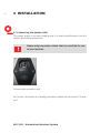
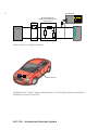
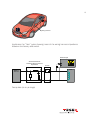
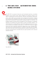
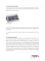
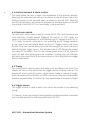
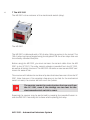
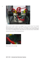
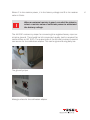
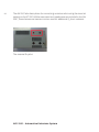
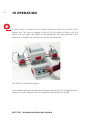
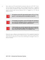
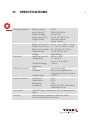
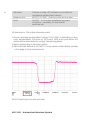
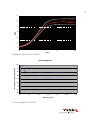
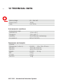
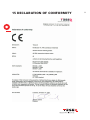
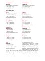
1
aes 5501 automotive
emissions system
User Manual
601-319B
AES 5501 Automotive
Emissions system
User Manual
AES 5501 - Automotive Emissions System
contentS
1.
Explanation of symbols used in this manual
2.
Warning symbols on the test system
3.Safety
4.Installation
4.1
Connecting the power cable
5.
Introduction to emissions in ISO 7637-2
6.
The AES 5501 - Automotive Emissions System
6.1
The system controller
6.2
Mechanical switch
6.3
Artifical network & shunt resistor
6.4
Electronic switch
6.5Timing
6.6
Trigger source
7.
The MS 5501
8.
The AN 5501
9.
The ES 5501 Electronic switch
10.Operation
11. Specifications
12. Technical data
13.Maintenance
13.1Cleaning
13.2Calibration
13.2.1 Calibrating the AN 5501
13.2.2 Calibrating the ES 5501
14
The package contents
15
Declaration of conformitiy (CE)
16Addresses
5
7
8
10
10
11
14
15
15
16
16
16
16
17
26
29
30
33
36
37
37
37
37
37
38
39
40
1 explanation of the symbols
used in this manual
Please take note of the following explanations of the symbols used in order
to achieve the optimum benefit from this manual and to ensure safety during
operation of the equipment.
The following symbol draws your attention to a circumstance where failing
to observe the warning could lead inconvenience or impairment in performance.
Example:
This connection must not be confused with the main
power input.
The following symbol draws your attention to a circumstance where failing
to observe the warning could lead to component damage or danger to the
operating personnel.
Caution sign: A situation that may cause damage to the equipment
Example:
Connect the system only to rated mains power.
5
6
Danger sign: Possibly dangerous situation that may cause damage to persons
or heavy damage to the test equipment or DUT.
Example:
It is dangerous to fail to observe safety warnings.
AES 5501 - Automotive Emissions System
2WArning symbols on the test
system
CAUTION! Warning of a danger spot (refer to the documentation).
7
8
3SAFETY
The AES 5501 system itself contains no dangerous voltages or currents,
however, the application requires an external power source and can use up to
100 A for DUT power.
Up to 100 A may be switched using the AES 5501. Care
should be taken in connecting and operating the DUT.
The AES 5501 system is used to measure emissions from the DUT. These emissions may be high voltages caused by inductive kickbacks. Care should be used
when powering the DUT through the AES 5501 system. Refer to engineering or
product documentation for your specific DUT.
Potentially dangerous voltage may be present at the
cables leading to and from the DUT. Take care and follow
all applicable safety guidelines given for your specific
DUT.
General warnings.
DANGER! It is imperative that you read the following
safety instructions and all safety instructions in the
manuals of the connected peripheral systems before
installing and starting this test system for the first
time.
AES 5501 - Automotive Emissions System
DANGER! The electrical and mechanical safety equipment must not be removed, put out of operation or
bypassed. Handle all safety equipment with care. If a
safety device should be broken or is not working, the
system must be put out of operation until the safety
device is repaired or exchanged and fully in working
order again.
DANGER! HAZARDOUS AREA! Connectors on the test
equipment should not be touched!
The equipment may only be operated within an area
that is explicitly declared a “Test Floor” (with appropriate signs) and protected against improper acces.
It is important to power off the DUT before disconnecting the DUT or any parts of the AES 5501.
The operating instructions form an integral part of the equipment and must be
available to the operating personnel at all times. All the safety instructions and
advice notes are to be observed.
9
10
4Installation
4.1 Connecting the power cable
The power supply is an auto ranging type. For exact specifications, see the
section technical specifications.
Please only use power cables that are certified for use
in your location.
Connecting the power cable
For further information on cabeling and setup please see the section “Operation”.
AES 5501 - Automotive Emissions System
5Introduction to emissions in
iso 7637-2
The AES 5501 is designed in accordance to ISO 7637-2 and may be used with
confidence for many manufacturer standards. This guide gives a good overview
of ISO 7637-2.
Carefully consult the relevant manufacturer standard
and ISO 7637-2 before operating the AES 5501 system.
ISO 7637-2:2004 describes a method of measuring transient returns from a DUT
when the battery is switched on or off. This standard is an important part of
automotive EMC testing. This standard describes two methods of switching the DUT: with a mechanical
switch (recommended the actual switch built into the vehicle) or a fast electronic
switch.
Refer to the applicable annex of ISO 7637-2 for guidance
in measuring the returned effects, and limits.
Pay special attention to cable lengths. The standards
have strict cable length requirements. The most
common are provided with the AES 5501 system.
ISO 7637-2 recommends two setups. The switch can be before or after the AN
as seen in the following diagrams. Refer to ISO 7637-2 for more information.
11
Oscilloscope
12
Switch
Artificial Network
Simulates Wiring Harness
Impedance
DUT
Battery
Source
Slow pulses (ms range or slower)
DU
T
Wiring Harness
Application for “Slow” pulse showing most of the wiring harness impedance
between the switch and DUT.
AES 5501 - Automotive Emissions System
13
D
UT
Wiring Harness
Application for “Fast” pulse showing most of the wiring harness impedance
between the battery and switch.
Oscilloscope
Artificial Network
Simulates Wiring Harness
Impedance
Battery
Source
Fast pulses (ns to μs range)
Switch
DUT
14
6The aes 5501 - automotive emissions system
The AES 5501 is a system of electronic and mechanical switches, an artificial
network, and a unique control station designed for emissions testing to ISO
7637-2. Consisting of a four-part solution, the user has complete control over
where, when and how the switches can be placed and controlled, including
the necessary drive voltages for the relays. The 100 A connectors are carefully
placed and countersunk to allow precise cabling between the switches, the
artificial network and test bench and allows for the electronic or mechanic
switches to be placed at any point before or after the artificial network. This
careful attention to switch placement and cable length means that the numerous manufacturer standards can also be met. The AES 5501 features a rugged
construction with unpainted underside for good earth contact, precise switching control and monitoring functions. A counter for the relay and LED indicators for both electronic and mechanical electronic switches are provided. The
ES 5501 has temperature controlled fans for quiet operation and a thermal
shutdown feature.
The AES 5501
AES 5501 - Automotive Emissions System
6.1 The system controller
The system controller SC 5501 is used to control timing and provide the necessary voltages for the AES 5501 system, and provide a convenient method of
selecting the various functions..
The SC 5501
The SC 5501 is broken into several fields depending on their functions: Mechanical switch, artificial network & shunt resistor, electronic switch, trigger source
and timings.
The following sections will provide details about these various control elements.
6.2 Mechanical switch
The mechanical switch field is used to control the MS 5501 and contains three
input elements: buttons named triggered, Off and On. In “Off” mode, the
switch is turned completely off, thus blocking any DC voltage to the DUT. In
“On” mode, the switch is turned on, thus providing any DC voltage available
at the input of the mechanical switch to the DUT. Trigger mode is the mode by
which the user has the ability to control the timing of the switch using the fields
timing and trigger source. This field also has an LED display that shows the
status of the switch. The switch will indicate green when it is on (conducting),
and unlit when off. red indicates an error condition. Pressing the unlit indicator
will select the mode. Refer to the descriptions of the timing field and trigger
source fields below.
15
16
6.3 Artifical network & shunt resistor
This field allows the user to select the impedance of the artificial network. Selecting the resistance here will set the resistor on the left (input) side of the
artificial network to the selected value, as shown on the AN 5501. Selecting
the Off/Exernal option, will connect the resistor to the banana jacks on the left
(input) side of the AN 5501. For more details, consult section 8.
6.4 Electronic switch
The electronic switch field is used to control the ES 5501 and contains three
input elements: buttons named Triggered, Off and On. In “Off” mode, the
switch is turned completely off, thus blocking any DC voltage to the DUT. In
“On” mode, the switch is turned on, thus providing any DC voltage available
at the input of the mechanical switch to the DUT. Trigger mode is the mode
by which the user has the ability to control the timing of the switch using the
fields timing and trigger source. This field also has an LED display that shows
the status of the switch. The LED will indicate green when it is on, and unlit
when off, and red indicating an error condition. Pressing the unlit indicator
will select the mode. Refer to the descriptions of the timing field and trigger
source fields below.
6.5 Timing
The timing field is used to select the battery off, and battery on times. The
battery on time is only valid when the trigger source is set to Internal. The
battery off time is used only when trigger source mode is internal or single. Both the battery off and battery on times may be set using the included dials
between approximately 10 ms and 10 s (see specifications for exact timings.)
6.6 Trigger source
The trigger source is used to select the source and mode of the switching
timing.
In “internal” mode, the timing of both repetition and disconnection is selected
with the dials provided in the timing field of the SC 5501.
AES 5501 - Automotive Emissions System
In “single mode”, the timing of the pulse will be selected by the battery off
(TOFF) dial in the timing field of the SC 5501. There will be no repetition in single
mode. To activate a pulse, press the trigger button under the “single” button
when selected.
In “manual” mode, the timing is dependant on how long the trigger is depressed. To start a pulse (battery voltage off), depress the trigger button (under the manual button) with manual selected. To end the pulse (allow battery
voltage to the DUT), release the trigger button.
In “external” mode, the user supplies a TTL signal on the BNC located at the
back side of the SC 5501. The battery output will follow the signal: A high
input to the trigger in BNC will result in battery voltage available to the DUT
(selected switch ON).
The input signal may be between ~4.5 and 12 V and is a differential input.
Control cables (Interchangeable)
Trigger in
Trigger out
Connectors on the SC 5501
17
7 The MS 5501
The MS 5501 is the container of the mechanical switch (relay).
125 m
m
50 mm
18
The MS 5501
The MS 5501 is delivered with a 100 A relay. Refer to section 6 for control. The
100 A relay may be exchanged using the supplied PCB for other relays that use
the industry standard footprint.
Before using the MS 5501, you must connect the control cable from the MS
5501 to the SC 5501. The relay control voltage is provided from the SC 5501,
as well as all timing functions. The MS 5501 contains an counter and BNC connector for ease of use.
The counter will indicate the number of pulses that have been sent from the SC
5501. Note that even if the repetition frequency is too fast for the mechanical
switch to react, the counter will still count the pulses.
.
The counter counts the control pulses that are sent from
the SC 5501, even if the timings are too fast for the
electromechanical switch to react.
Resetting the counter may be performed by pressing the provided button inside the MS 5501. Normally this is done when replacing the relay.
AES 5501 - Automotive Emissions System
19
Resetting the counter
The MS 5501 is provided with a 100 A relay installed by default. The PCB adapter with a selection of industry standard footprints may also be installed by
performing the following steps.
Opening the housing should be achieved by removing the four thumb screws
indicated in the following picture and gently lifting the handles outwards and
upwards.
Opening the housing
20
Removing the housing cover
The old relay must be removed. Start by removing the cables connecting the
relay to the input and output posts (high side only) using a 10 mm wrench. This
will be performed two times, on the input and output sides of the MS 5501.
AES 5501 - Automotive Emissions System
The system should appear as in the following picture when the relay is
removed:
Uninstalled 100 A relay
21
22
It should never be necessary to remove the negative
connections inside the MS 5550. The AES 5501 was
designed, in accordance to the standards, to open only
the positive battery lead.
Reinstalling the 100 A relay may be achieved by reversing the above steps.
Installing the included PCB with standard relay footprints may be installed using the following process.
Install the supplied studs and the PCB using the supplied hardware a screwdriver with T25 bit.
Install the relay PCB
The studs will require the use of washers (included)
between the base of the ES 5501 and the stud.
AES 5501 - Automotive Emissions System
The PCB containing the relay sockets uses two studs
included with the AES 5501 system.
Next, connect the included cabling. This includes two sets: two short battery
cables, and a six-pin cable.
The six-pin cable provides the necessary drive voltages to the relay. Take care
when installing this cable.
The two red battery cables should be connected from the battery studs to the
common and normally open connections as shown.
23
24
Next you will need to select the voltage for your specific relay. The included
Bosch relay is part number 0 332 019 151 and uses a 12 V drive voltage. The
AES 5501 system was designed to include 12, 24 and 42 (36) volt drive voltages
to the relay. The voltage for the relay comes over the short six pin cable and is
selected as shown in the following picture.
Selecting the drive voltage
AES 5501 - Automotive Emissions System
Carefully select the drive voltage of the relay installed
before connecting the drive cable to the MS 5501.
Degradation in performance or damage may result in
incorrectly selected drive voltages.
The limitation in the supplied Bosch relay is 30 A. If
another relay is installed, the entire system’s performance must be adapted to the relay current.
The MS 5501 may be closed again using a reverse process of that given above,
and reconnecting the six screws and the drive cable from the SC 5501.
Please note that the coil suppression diode is required.
Mind the polarity of the diode when exchanging
relays.
25
26
8 the an 5501
The AN 5501 contains the artificial network rated to 100 A, the necessary selectable impedance, an extra banana connector for external impedances and an
output connector for monitoring if necessary.
The AN 5501
The AN 5501 shall be connected to the SC 5501 using the supplied control cable. As in any of these external chassis, it is not important which cable is connected;
any of the three available may be used.
To select the RS resistor, choose the appropriate resistance value on the SC
5501. If an external resistor shall be used, selecting off/external on the SC 5501
will activate the Ext. R connector. Pay attention that a resistor of sufficient
power is used based on your battery voltage using the following formula.
P = U2/R
AES 5501 - Automotive Emissions System
Where P is the resistor power, U is the battery voltage and R is the resistor
value in Ohms.
When an external resistor is used, care shall be taken to
select a resistor value of sufficient power to withstand
the battery voltage.
The AN 5501 contains a jumper for connecting the negative battery input terminal to ground. This should be left connected usually (and is required for
conformance to ISO 7637). The output side of the AN also contains a special
connection for the calibration adapter. This can be ignored during daily use.
The ground jumper
Mating surface for the calibration adapter
27
28
The AN 5501 also has a place for connecting a resistor when using the external
setting on the SC 5501. While most common impedances are included in the AN
5501, these banana connectors can be used for additional RS shunt resistors.
The external Rs jacks
AES 5501 - Automotive Emissions System
9 the es 5501 electronic switch
The ES 5501 is the container of the electronic switch with specifications outlined
in ISO 7637-2.
The ES 5501
The ES 5501 is a 100 A fast electronic switch. Refer to chapter 6 for control.
Before using the ES 5501, you must connect the control cable from the ES 5501
to the SC 5550. The ES 5501 contains a BNC connector for ease of use.
29
30
10operation
In every case, it is important to consider where the input and outputs of the
system are. The input is always to the left of the various chassis, and the
output is on the right. The cables are exchangeable, as is the positions of the
switches, as long as the inputs and outputs are observed.
The AES 5501 Emissions system
In the above example (here shown with both switches) the DC voltage (battery)
comes in the left side and the DUT would be connected on the right.
AES 5501 - Automotive Emissions System
Carefully observe cable placement, observing maximum cable lengths and
cable placing requirements of your standard.
It is important to observe proper polarity when connecting the oscilloscope probe. Most oscilloscope probes
have a ground connection. The AN 5501 is not isolated
and failing to observe proper polarity can cause a short
of the power supply to ground!
Once all cables are in place and the various lengths of cables are observed,
provide the DC voltage to the DUT by switching both the Mechanical Switch
and Electronic Switch to “On”.
The AES 5501 can also be used with the supplied pins. The allows the user to
effectively have zero distance between the AN and switches.
The AES 5501 being configured for zero cable length
31
32
Next, select your RS by selecting the resistance value on the SC 5501. To perform the slow pulse, for example, select the Mechanical Switch -> Triggered,
and use either the Manual, Single, Internal fields to select the timing. Any
switch in the DC path must be selected “ON” or “Triggered” or “DC” will not
pass to the DUT.
All switches in the DC path must be set to “On” or “Triggered” or no battery will be available to the DUT.
Throughout the system, a green LED means DC switched
on, a red LED indicates an error condition, and an unlit
LED indicates that the switch is switched off.
Cable lengths are strictly required by most standards,
as is the cable height above the ground plane. Observe
these restrictions carefully for a compliant test.
After all of your cables are connected and the DUT is powered through the
switch(es) then you are ready to create a dropout. Note that the worst emissions returns usually occur at the time of switching the voltage off due to inductive kickback.
AES 5501 - Automotive Emissions System
11Specifications
Complete system1:
Electronic:
Mechanical switch:
Artificial network:
Connectors:
Housing:
Battery current
100 A
Inrush current 2
300 A for 200 ms
Battery voltage
0 to 60 VDC
Shunt resistor (RS)
10, 20, 40, 120 Ω, Ext.
Trigger modes
External, internal,
single, manual
Battery off time (TOff ) 10 ms - 10 s ± (10% + 10 ms)
Battery on time (TOn) 0.5 - 10.5 s ± (10% + 10 ms)
Mains input voltage 85 - 264 VAC, 47 - 63 Hz
Available relay
12, 24, 36V (for 42 V
voltage
applications)
Switching time Δts 300 ns ± 20%3
Voltage drop
<1 V @ 25 A
Typ. < 2.1 V @ 100 A
Transient voltage
> 440 V
protection
Type
Automotive relay
Contacts
High purity AgNi with no
suppression across contacts
Voltage rating
> 400 V
Inductance
5 μH
Capacitance
0.1 μF
Resistance
50 Ω
Impedance
As per ISO 7637-2 see above
impedance curve
100A MC type, countersunk, 50 mm above ground
plane
Stainless steel, unpainted underside, screw
terminal and earth connections
33
34
Indicators:
Measurement:
Ports:
Counter on relay, LED indicator on controller for
mechanical and electronic switchs
MS 5501, ES 5501 - directly connected to output
AN 5501 - 5.6 k output impedance (to output
connector - necessary for improved RF
performance)
All tolerances ± 10% unless otherwise noted.
1) Active, temperature dependant cooling. The ES 5501 is depending on duty
cycle, approximately 3 minutes at 100 A with 100% duty cycle before the
switch will be deactivated for cooling. See derating below.
2) With supplied relay or Electronic Switch
3) With test load defined in ISO 7627-2. Purely resistive loads display typically
in the range of a few microseconds.
ES 5501 switching curve with test load
AES 5501 - Automotive Emissions System
35
60
50
40
Z[Ω]
PB
│
30
20
10
0
0.1
1
10
Impedance curve of the AN 5501
100
f [MHz]
Derateing ES 5501
Ion (100% Duty Cycle, @25°C) [A]
100
95
90
85
80
75
70
65
60
0
10
20
30
ON-Tim e [m in]
Current capability of ES 5501
40
50
60
36
12Technical data
Mains voltage:
Power (max.):
Fuse:
85 ... 264 VAC
100 W
2 x T 3.15A
Environmental conditions
Temperature range
Operation at:
Storage at:
Humidity:
Air pressure:
+10 to +40º C
-10 to +60 º C
30 to 78% (non condensing)
860 to 1060 hPa
Dimensions and weights
Physical
Dimensions (L x W x H):
MS 5501
AN 5501
Weight:
MS SC 5501
AN 5501
ES 5501
125 x 125 x 125 mm
125 x 125 x 125 mm
340 x 270 x 205 mm
ES 5501
3.4 kg
2.4 kg
2.9 kg
10 kg
AES 5501 - Automotive Emissions System
13Maintenance
Except for the relay in the MS 5501, there are no user serviceable parts inside.
For fuse selection, please see the section on technical data.
13.1 Cleaning
Cleaning the AES 5501 should be performed using only a clean, dry cloth. No
detergents of any kind are recommended.
13.2 Calibration
The AES 5501 has two parts requiring calibration: The ES 5501 and AN 5501.
13.2.1 Calibrating the AN 5501
Calibration of the AN 5501 is performed using the calibration kit INA 5500-CK
which provides a shorting connector for the input side and a MC to N-Type
connector for the output side where the network analyzer is connected. The
grounding plug must be in place during calibration.
For more details on calibration, see the calibration procedure and documentation included in the INA 5500-CK.
13.2.1 Calibrating the ES 5501
Calibration of the ES 5501 is performed using the test load defined in ISO
7637-2. This is available under model number INA 5500-TL. The switching time
of 300 ns is only valid using this load. Resistive loads and open circuit measurement will be different.
37
38
14The package contents
Inside the packaging, you will find the following items:
1 x MS 5501 Mechanical switch
1 x ES 5501 Electronic switch
1 x SC 5501 System controller
3 x Control cables
Calibration certificate
Users guide (this guide)
Oscilloscope probe compliant to ISO 7637-2
4 x Pin adapters (for zero millimetres between devices)
4 x 4 to 6 mm adapters
2 x Alternative relay PCB, cable and hardware
AES 5501 - Automotive Emissions System
15Declaration of conformity
39
Headquarters
Teseq AG
4542 Luterbach, Switzerland
T + 41 32 681 40 40
F + 41 32 681 40 48
sales @ teseq.com
www.teseq.com
Manufacturer
Teseq AG
4542 Luterbach, Switzerland
T + 41 32 681 40 40
F + 41 32 681 40 48
sales @ teseq.com
China
Teseq Company Limited
T + 86 10 8460 8080
F + 86 10 8460 8078
chinasales @ teseq.com
France
Teseq Sarl
T + 33 1 39 47 42 21
F + 33 1 39 47 40 92
francesales @ teseq.com
Germany
Teseq GmbH
T + 49 30 5659 8835
F + 49 30 5659 8834
desales @ teseq.com
Japan
Teseq K.K.
T + 81 3 5725 9460
F + 81 3 5725 9461
japansales @t eseq.com
Singapore
Teseq Pte Ltd.
T + 65 6846 2488
F + 65 6841 4282
singaporesales @ teseq.com
Switzerland
Teseq AG
T + 41 32 681 40 50
F + 41 32 681 40 48
sales @ teseq.com
Taiwan
Teseq Ltd.
T + 886 2 2917 8080
F + 886 2 2917 2626
taiwansales @ teseq.com
UK
Teseq Ltd.
T + 44 845 074 0660
F + 44 845 074 0656
uksales @ teseq.com
USA
Teseq Inc.
T + 1 732 417 0501
F + 1 732 417 0511
Toll free +1 888 417 0501
usasales @ teseq.com
© December 2010 Teseq®
Specifications subject to change
without notice. Teseq® is an ISOregistered company. Its products are
designed and manufactured under
the strict quality and environmental
requirements of the ISO 9001. This
To find your local partner within document has been carefully checked.
Teseq®’s global network, please go to However, Teseq® does not assume
www.teseq.com
any liability for errors or inaccuracies.