1
Stratos®Pro A4... MSCONDI
User Manual
MEMO
SENS
Latest Product Information:
www.knick.de
Warranty. Disposal. About This Manual.
Warranty
Defects occurring within 3 years from delivery date shall be remedied
free of charge at our plant (carriage and insurance paid by sender).
Sensors, fittings and accessories: 1 year.
Subject to change without notice.
Return of products under warranty
Please contact our Service Team before returning a defective device.
Ship the cleaned device to the address you have been given.
If the device has been in contact with process fluids, it must be decontaminated/disinfected before shipment. In that case, please attach
a corresponding certificate, for the health and safety of our service
personnel.
Disposal
Please observe the applicable local or national regulations concerning
the disposal of “waste electrical and electronic equipment”.
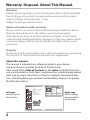
About this manual:
This manual is intended as a reference guide to your device –
You don't have to read the book from front to back.
Take a look at the Table of Contents or the Index to find the function
you are interested in. Each topic is explained on a double-page spread
with step-by-step instructions on how to configure the desired function. Clearly legible page numbers and headlines help you to quickly
find the information:
Configuration
CONTROL input (FLOW MIN, FLOW MAX)
1
Left page:
How do I get to
the function
2
enter
3
Configuration
5
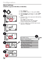
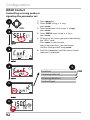
Alarm Settings
1) Pressmenukey.
2) SelectCONFusingkeys,pressenter.
3) Selectparametersetusingkeys,press
enter.
4) SelectALARMmenuusingkeys,press
enter.
5) Allitemsofthismenugroupareindicatedby
the“ALA:”code.
Pressentertoselectmenu,
editusingarrowkeys(seenextpage).
Confirm(andproceed)usingenter.
6) End:Pressmeas keyuntilthe[meas]mode
indicatorisdisplayed.
Menu item
Action
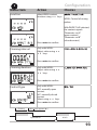
CONTROLinput
TheCONTROL inputcan
generateanalarmwhen
assignedtoFLOW(flow
monitoring)intheCONF
menu:
FLOW CNTR
Flow measurement:
allowsmonitoringthe
minimumandmaximum
flow(pulsecounter)
Choices
Alarm
Minimumflow
Specifyvalue
Default:05.00liters/h
Alarm
Maximumflow
Specifyvalue
Default:25.00liters/h
Right page:
Which settings
are provided for
this function
FLOW MIN
FLOW MAX
enter
4
5
enter
5
meas
ALARM:Delay
Alarm:Sensocheck
Alarm:CONTROLinput
Forflowmonitoring:
Max.flowalarm
Forflowmonitoring:
Min.flowalarm
enter
6
68
2
69
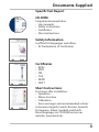
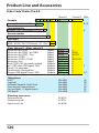
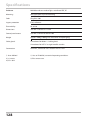
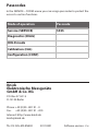
Documents Supplied
Specific Test Report
CD-ROM
Complete documentation:
• User manuals
• Safety instructions
• Certificates
• Short instructions
Safety Information
In official EU languages and others.
• EC Declarations of Conformity
Certificates
•
•
•
•
•
•
IECEx
ATEX
FM
CSA
NEPSI
GOST
Short Instructions
First steps after installation:
• Operation
• Menu structure
• Calibration
• Error messages and recommended actions
In German, English, French, Russian, Spanish,
Portuguese, Italian, Swedish and Dutch.
More languages on CD-ROM and on our
website: www.knick.de
3
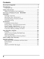
Contents
Documents Supplied...................................................................... 3
Introduction..................................................................................... 7
Intended Use.......................................................................................... 7
Safety Information........................................................................12
Safety Precautions for Installation................................................13
Overview of Stratos Pro A4... MSCONDI...................................14
Assembly.........................................................................................15
Package Contents...............................................................................15
Mounting Plan, Dimensions...........................................................16
Pipe Mounting, Protective Hood...................................................17
Panel Mounting...................................................................................18
Installation......................................................................................19
Installation Instructions....................................................................19
Rating Plates / Terminal Assignments.........................................20
Power Supply, Signal Lines..............................................................21
Wiring Example: SE 670 (via RS-485)...........................................22
Protective Wiring of Relay Contacts.............................................24
User Interface, Keypad.................................................................26
Display....................................................................................................27
Signal Colors (Display Backlighting)............................................27
Measuring Mode.................................................................................28
Selecting the Mode / Entering Values.........................................29
Color-Coded User Interface.........................................................31
Operating Modes...........................................................................32
Menu Structure of Modes and Functions..................................33
HOLD Mode..........................................................................................34
Alarm.......................................................................................................35
Alarm and HOLD Messages.............................................................36
4
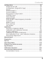
Contents
Configuration.................................................................................38
Parameter Set A/B...............................................................................40
Configuration (Original for Copy).................................................46
Sensor......................................................................................................50
Current Output 1.................................................................................56
Current Output 2.................................................................................66
Temperature Compensation...........................................................68
CONTROL Input...................................................................................72
Alarm Settings......................................................................................74
Limit Function......................................................................................78
Pulse Length / Pulse Frequency Controller...............................87
Controller . ............................................................................................88
WASH Contact......................................................................................92
Time and Date......................................................................................94
Tag Number .................................................................................................94
Calibration......................................................................................97
Selecting a Calibration Mode.........................................................97
Calibration with Calibration Solution..........................................98
Product Calibration..........................................................................100
Calibration by Input of Cell Factor..............................................102
Zero Calibration in Air / with Calibration Solution...............103
Temp Probe Adjustment................................................................104
Measurement...............................................................................105
Diagnostics...................................................................................108
Service...........................................................................................113
Operating States..........................................................................118
Product Line and Accessories...................................................120
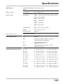
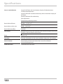
Specifications...............................................................................121
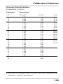
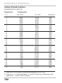
Calibration Solutions..................................................................129
Concentration Measurement....................................................131
Concentration Curves......................................................................132
5
Contents
Error Handling..............................................................................138
Error Messages.............................................................................139
Sensoface......................................................................................141
FDA 21 CFR Part 11.....................................................................143
Electronic Signature – Passcodes................................................143
Audit Trail.............................................................................................143
Index..............................................................................................144
Trademarks..........................................................................................155
Passcodes......................................................................................156
6
Introduction
Intended Use
Stratos Pro A4... MSCONDI is a 4-wire device for measurement of
electrical conductivity and temperature in liquids using electrodeless
(toroidal) sensors. Fields of application are: biotechnology, chemical
industry, environment, food processing, water/wastewater treatment.
Enclosure and mounting possibilities
• The sturdy molded enclosure is rated IP 67/NEMA 4X for outdoor
use. It is made of glass-reinforced PBT / PC and measures
148 mm x 148 mm x 117 mm (H x W x D).
It is provided with knockouts to allow:
• wall mounting (with sealing plugs to seal the enclosure),
see page 15
• post/pipe mounting (Ø 40 … 60 mm, 30 … 45 mm)
see page 17
• panel mounting (138 mm x 138 mm cutout to DIN 43700),
see page 18
Weather protector (accessory)
The weather protector, which is available as accessory, provides
additional protection against direct weather exposure and
mechanical damage, see page 17.
Connection of sensors, cable glands
For connecting the cables, the enclosure provides
• 3 knockouts for cable glands M20x1.5
• 2 knockouts for NPT 1/2” or rigid metallic conduit
For quasi-stationary installations with Memosens sensors, we
recommend using the M12 device socket (accessory ZU 0822) instead
of a cable gland – it allows simple replacement of the sensor cable
without opening the device.
Sensors
The device has been designed for application with the Model 670
electrodeless sensor (Knick).
7
Introduction
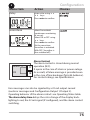
Display
Plain-text messages in a large, backlit LC display allow intuitive
operation. You can specify which values are to be displayed in
standard measuring mode ("Main Display", see page 30).
Color-coded user interface
The colored display backlighting signals different operating states
(e.g. alarm: red, HOLD mode: orange, see page 31).
Diagnostics functions
“Sensocheck“ automatically monitors sensor and cables; and the
“Sensoface“ function clearly indicates the sensor condition,
see page 108.
Data logger
The internal logbook (TAN SW-A002) can handle up to 100 entries –
up to 200 with AuditTrail (TAN SW-A003), see page 111.
2 parameter sets A, B
The device provides two parameter sets which can be switched manually or via a control input for different process adaptations or different
process conditions.
For overview of parameter sets (table for copy), see page 46.
Password protection
Password protection (passcodes) for granting access rights during
operation can be configured, see page 116.
TC process medium: Selecting the compensation method
The following temperature compensation methods are provided:
linear (by entering a temperature coefficient), natural waters (nLF),
NaCl, see page 68.
8
Introduction
Control inputs
5
Current
6
11
input
HOLD
input
I input
The analog (0) 4 ... 20 mA current input can
be used for external temperature compensation (TAN required).
See page 70.
HOLD
(floating digital control input)
The HOLD input can be used for external
activation of the HOLD mode, see page 35.
12
CONTROL
13
input
CONTROL
(floating digital control input)
The CONTROL input can be used either for
parameter set selection (A/B) or for flow
monitoring, see page 72.
The “Wash” contact can be used for
indicating the active parameter set
(see next page).
Power supply
Current is provided through a universal power supply
24 ... 230 V AC/DC, AC: 45 ... 65 Hz.
Options
Additional functions can be activated by entering a TAN (page 116).
9
Introduction
Signal outputs
The device provides two current outputs (for transmission of
measured value and temperature, for example). The output curve is
adjustable (linear, bilinear or logarithmic), see page 56 et seq.
Relay contacts
Four floating relay contacts are available.
Output 1
9
10
Output 2
7
8
R1
14
15
R2
16
Alarm
17
R3
18
Wash
19
R4
20
Current outputs
The floating current outputs (0) 4 ... 20 mA
are used for transmitting measured values.
The output curve can be linear, bilinear or
logarithmic. An output filter can be programmed, the fault current value can be
specified. See page 56 et seq.
Relay contacts
2 relay contacts for limit values. Adjustable
for the selected process variable: hysteresis,
switching behavior (MIN/MAX limit), contact type (N/O, N/C) and delay (page 78).
Alarm
An alarm can be generated by Sensocheck,
flow monitoring or current failure
(page 74).
Wash (cleaning function)
This contact can be used for controlling a
rinsing probe or for indicating the active
parameter set (page 92).
PID controller
Configurable as pulse length or pulse frequency controller (page 88).
10
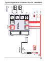
Typical Application of Stratos Pro A4... MSCONDI
11
Safety Information
Be sure to read and observe the following safety instructions!
The device has been manufactured using state of the art technology
and it complies with applicable safety regulations.
When operating the device, certain conditions may nevertheless lead
to danger for the operator or damage to the device.
See also the following documents (page 3):
• "Safety Instructions"
• "Certificates"
CAUTION!
Commissioning must only be performed by trained personnel authorized by the operating company! Whenever it is likely that protection
has been impaired, the device shall be made inoperative and secured
against unintended operation.
The protection is likely to be impaired if, for example:
• the device shows visible damage
• the device fails to perform the intended measurements
• after prolonged storage at temperatures below –30 °C or above
70 °C
• after severe transport stresses
Before recommissioning the device, a professional routine test must
be performed. This test must be carried out at the manufacturer’s
factory.
Please note:
Before commissioning you must prove that the device may be
connected with other equipment.
12
Safety Information
Safety Precautions for Installation
• The electrical installation shall conform to the national regulations
for electrical installations and/or other applicable national or local
codes or regulations.
• The power supply shall be disconnectable from the device by a
two-poled circuit breaker.
• Switch and circuit breaker shall be located in close proximity to the
equipment and be easily accessible by the OPERATOR. They shall be
marked as disconnect switch for the device.
• Be sure to disconnect the mains supply and any relay contacts
which are connected to separate current sources before starting
maintenance operations.
Approvals for application in hazardous locations:
Stratos Pro A4...B MSCONDI: see Specifications, copies provided in the
"Certificates" document: IECEx, ATEX, FM, CSA, NEPSI and GOST.
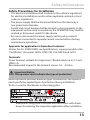
Terminals:
2
Screw terminal, suitable for single wires / flexible leads up to 2.5 mm
(AWG 14).
Recommended torque for the terminal screws: 0.5 ... 0.6 Nm.
Important Notice:
The operator must indicate the type of protection!
When the device provides different types of protection, the operator
must specify the applied type of protection during installation.
To do so, use the checkboxes on the rating plate:
Additional rating plate at outside bottom of front with checkboxes for marking the respective application after installation
13
Overview
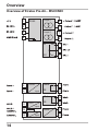
Overview of Stratos Pro A4... MSCONDI
1
RS 485
Output 1
2
9
10
3
Output 2
4
7
8
R1
14
15
R2
16
5
Current
Alarm
17
6
input
R3
18
Wash
19
R4
20
Power
21
11
HOLD
input
12
Control
13
14
input
22
Assembly
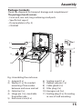
Package Contents
Check the shipment for transport damage and completeness!
The package should contain:
• Front unit, rear unit, bag containing small parts
• Specific test report
• Documentation (cf p. 3)
• CD-ROM
1
11
10
2
3
9
8
7 6
5
4
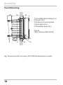
Fig.: Assembling the enclosure
1) Jumper (3 x)
2) Washer (1 x), for conduit
mounting: Place washer
between enclosure and nut
3) Cable tie (3 x)
4) Hinge pin (1 x), insertable
from either side
5) Enclosure screw (4 x)
6) Sealing insert (1 x)
7) Rubber reducer (1 x)
8) Cable gland (3 x)
9) Filler plug (3 x)
10) Hexagon nut (5 x)
11) Sealing plug (2 x), for sealing
in case of wall mounting
15
Assembly
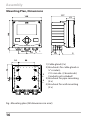
Mounting Plan, Dimensions
117
41
14
148
148
42
6.2
74
34
42
42
1
21
43
80
1)Cable gland (3 x)
2)Knockouts for cable gland or
½” conduit,
21.5 mm dia. (2 knockouts)
3
Conduits not included!
3)Knockout for pipe mounting
4
(4 x)
4)Knockout for wall mounting
(2 x)
Fig.: Mounting plan (All dimensions in mm!)
16
2
Assembly
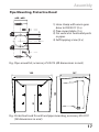
Pipe Mounting, Protective Hood
ø40...ø60
1
2
3
1)Hose clamp with worm gear
drive to DIN 3017 (2 x)
2)Pipe-mount plate (1 x)
3)For vertical or horizontal posts
or pipes
4)Self-tapping screw (4 x)
4
Fig.: Pipe-mount kit, accessory ZU 0274 (All dimensions in mm!)
147
91
185
199
Fig.: Protective hood for wall and pipe mounting, accessory ZU 0737
(All dimensions in mm!)
17
Assembly
Panel Mounting
< 30
76
31
1)Circumferential sealing (1 x)
2)Screws (4 x)
3)Position of control panel
4)Span piece (4 x)
5)Threaded sleeve (4 x)
Cutout
138 x 138 mm (DIN 43700)
1
1...22
5
4
3
2
Fig.: Panel-mount kit, accessory ZU 0738 (All dimensions in mm!)
18
Installation
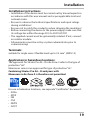
Installation Instructions
• Installation of the device must be carried out by trained experts in
accordance with this user manual and as per applicable local and
national codes.
• Be sure to observe the technical specifications and input ratings
during installation!
• Be sure not to notch the conductor when stripping the insulation!
• Before connecting the device to the power supply, make sure that
its voltage lies within the range 20.5 to 253 V AC/DC!
• The supplied current must be galvanically isolated. If not, connect
an isolator module.
• All parameters must be set by a system administrator prior to
commissioning!
Terminals:
suitable for single wires / flexible leads up to 2.5 mm2 (AWG 14)
Application in hazardous locations:
The approvals for Stratos Pro A4... B in Ex Zone 2 refer to the type of
protection “nA“.
Memosens sensors are approved for type of protection “nL“.
Combining Stratos Pro A4... B analyzers with
Memosens in Ex-Zone 2 is therefore not permitted.
For use in hazardous locations, see separate “Certificates“ document:
• IECEx
• ATEX
• FM
• CSA
• NEPSI
• GOST
19
Installation
Rating Plates / Terminal Assignments
Fig.: Terminal assignments of Stratos Pro A4...
Fig.: Stratos Pro A4...N rating plate at outside bottom of front
Fig.: Stratos Pro A4...B rating plate at outside bottom of front
Please note: The operator must indicate the type of protection!
When the device provides different types of protection, the operator
must specify the applied type of protection during installation.
To do so, use the checkboxes on the rating plate.
See also “Safety Information“ chapter.
Fig.:
Example of
an additional
approval plate.
The specifications
refer to the respective
device.
20
Power Supply, Signal Lines
Connect the power supply for Stratos Pro A4... MSCONDI
to terminals 21 and 22
(24 ... 230 V AC, 45 ... 65 Hz / 24 ... 80 V DC)
Terminal assignments
Areas for placing the
screwdriver to pull out
the terminals
1
22
Fig.: Terminals, device opened, back of front unit
21
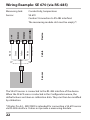
Wiring Example: SE 670 (via RS-485)
Conductivity, temperature
SE 670
Caution! Connection to RS-485 interface!
The measuring module slot must be empty*!
Cable
Sensor
Transparent
White
Yellow
Green
Brown
Device
Measuring task:
Sensor:
The SE 670 sensor is connected to the RS-485 interface of the device.
When the SE 670 sensor is selected in the Configuration menu, the
default values are taken as calibration data. They can then be modified
by calibration.
*)Stratos Pro A2... MSCONDI is intended for connecting a SE 670 sensor
via RS-485 interface. It does not provide a measuring module.
22
23
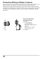
Protective Wiring of Relay Contacts
Relay contacts are subject to electrical erosion. Especially with
inductive and capacitive loads, the service life of the contacts will be
reduced. For suppression of sparks and arcing, components such as RC
combinations, nonlinear resistors, series resistors and diodes should
be used.
1
1
2
3
3
24
2
Typical AC applications
with inductive load
1) Load
2) RC combination,
e.g. RIFA PMR 209
Typical RC combinations for
230 V AC:
capacitor 0.1 µF / 630 V,
resistor 100 Ω / 1 W
3) Contact
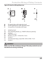
Protective Wiring of Relay Contacts
Typical Protective Wiring Measures
A:
B:
C:
DC application with inductive load
AC/DC applications with capacitive load
Connection of incandescent lamps
A1
A2
A3
B1
B2
B3
C1
C3
Inductive load
Free-wheeling diode, e.g. 1N4007 (Observe polarity)
Contact
Capacitive load
Resistor, e.g. 8 Ω / 1 W at 24 V / 0.3 A
Contact
Incandescent lamp, max 60 W / 230 V, 30 W / 115 V
Contact
WARNING!
Make sure that the maximum ratings of the relay contacts are not
exceeded even during switching!
25
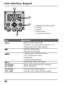
User Interface, Keypad
1
MEMO
SENS
2
3
4
Key
Function
•
•
•
•
•
•
•
Arrow keys
up / down
Arrow keys
left / right
26
1 IrDA transmitter/receiver
2 Display
3 Keypad
4 Rating plate
(enclosure bottom)
•
•
•
•
•
Return to last menu level
Directly to measuring mode (press > 2 s)
Measuring mode: other display
Retrieve information
Show error messages
Configuration: Confirm entries,
next configuration step
Calibration:
Continue program flow
Measuring mode: Call menu
Menu: Increase/decrease a numeral
Menu: Selection
Previous/next menu group
Number entry: Move between digits
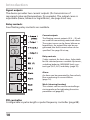
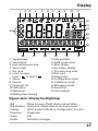
Display
1
2
3
4
5
6
7
8
9
10
11
MEMO
SENS
23
12
13
14
24
15
16
22
21
1 Temperature
2 Sensocheck
3 Interval/response time
4 Sensor data
5 Not used
6 Limit message:
Limit 1
or Limit 2
7 Alarm
8 Service
9 Parameter set
10Calibration
11Memosens
12Waiting time running
20
19
18
17
13Info available
14Hold mode active
15Main display
16Secondary display
17Proceed using enter
18Not used
19Diagnostics
20Configuration mode
21Calibration mode
22Measuring mode
23Sensoface
24Unit symbols
Signal colors (display backlighting)
Red
Red blinking
Orange
Turquoise
Green
Purple
Alarm (in case of fault: display values blink)
Input error: illegal value or wrong passcode
HOLD mode (Calibration, Configuration, Service)
Diagnostics
Info
Sensoface message
27
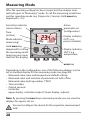
Measuring Mode
After the operating voltage has been connected, the analyzer automatically goes to “Measuring“ mode. To call the measuring mode from
another operating mode (e.g. Diagnostics, Service): Hold meas key
depressed (> 2 s).
Sensoface indicator
(sensor status)
Time
(or flow)
Mode indicator
(measuring)
Hold meas key
depressed for calling
the measuring mode
(pressing once more
switches the display)
Active
parameter set
(configuration)
Display indicates
OUT1: e.g.
process variable
Display indicates
OUT2: e.g.
temperature
enter key
Depending on the configuration, one of the following displays can be
set as standard display for the measuring mode (see page 30):
• Measured value, time and temperature (default setting)
• Measured value and selection of parameter set A/B or flow
Measured value and tag number ("TAG")
• Time and date
• Output currents
• Controller:
upper display: controller output Y, lower display: setpoint
Note: By pressing the meas key in measuring mode you can view the
displays for approx. 60 sec.
You must configure the device for the respective measurement
task!
28
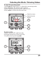
Selecting the Mode / Entering Values
To select the operating mode:
1)Hold meas key depressed (> 2 s) (directly to measuring mode)
2)Press menu key: the selection menu appears
3)Select operating mode using left / right arrow key
4)Press enter to confirm the selected mode
Selection menu
Selected mode
(blinks)
4
1
3
2
To enter a value:
5)Select numeral: left / right arrow key
6)Change numeral: up / down arrow key
7)Confirm entry by pressing enter
5
7
6
29
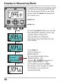
Display in Measuring Mode
The MAIN DISPLAY is the display which
is shown in measuring mode. To call
the measuring mode from any other
mode, hold the meas key depressed
for at least 2 sec.
meas key
enter key
meas
meas
enter
approx. 2 s
30
By pressing meas briefly you can step
through further displays such as tag
number (TAG) or flow (L/h).
These displays are turquoise.
After 60 sec they switch back to the
main display.
Press enter to
select a display as
MAIN DISPLAY –
the secondary display shows
"MAIN DISPLAY – NO“.
Use the UP / DOWN arrow keys to
select "MAIN DISPLAY – YES“
and confirm by pressing enter.
The display color changes to white.
This display is now shown in
measuring mode.
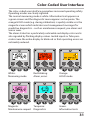
Color-Coded User Interface
The color-coded user interface guarantees increased operating safety.
Operating modes are clearly signaled.
The normal measuring mode is white. Information text appears on
a green screen and the diagnostic menu appears on turquoise. The
orange HOLD mode (e.g. during calibration) is quickly visible as is the
magenta screen which indicates asset management messages for
predictive diagnostics – such as maintenance request, pre-alarm and
sensor wear.
The alarm status has a particularly noticeable red display color and is
also signaled by flashing display values. Invalid inputs or false passcodes cause the entire display to blink red so that operating errors are
noticeably reduced.
White:
Measuring mode
Red blinking:
Alarm, errors
Turquoise:
Magenta:
Maintenance request Diagnostics
Orange:
HOLD mode
Green:
Information texts
31
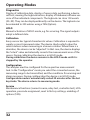
Operating Modes
Diagnostics
Display of calibration data, display of sensor data, performing a device
self-test, viewing the logbook entries, display of hardware/software versions of the individual components. The logbook can store 100 events
(00...99). They can be displayed directly on the device. The logbook can
be extended to 200 entries using a TAN (Option).
HOLD
Manual activation of HOLD mode, e.g. for servicing. The signal outputs
adopt a defined state.
Calibration
Every sensor has typical characteristic values. Calibration is required to
supply a correct measured value. The device checks which value the
sensor delivers when measuring in a known solution. When there is a
deviation, the device can be “adjusted“. In that case, the device displays
the “actual“ value and internally corrects the measurement error of the
sensor. During calibration the device is in HOLD mode.
During calibration the device remains in the HOLD mode until it is
stopped by the operator.
Configuration
The analyzer must be configured for the respective measurement
task. In the “Configuration“ mode you select the connected sensor, the
measuring range to be transmitted, and the conditions for warning and
alarm messages. During configuration the device is in HOLD mode.
Configuration mode is automatically exited 20 minutes after the last
keystroke. The device returns to measuring mode.
Service
Maintenance functions (current source, relay test, controller test), IrDA
operation, passcode assignment, reset to factory settings, enabling of
options (TAN).
32
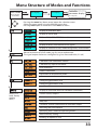
Menu Structure of Modes and Functions
Meas. mode
(main display
selectable)
TAG display
CLK display
after 60 s
after 60 s
Controller
parameter display
(if configured)
Pressing the menu key (down arrow) opens the selection menu.
Select the menu group using the left/right arrow keys.
Pressing enter opens a menu item. Press meas to return.
Display of calibration data
Display of sensor data
Self test: RAM, ROM, EEPROM, module
Logbook: 100 events with date and time
Display of direct, uncorrected sensor signals
Display of software version, model designation, serial number
Manual activation of HOLD mode, e.g. for sensor replacement.
The signal outputs behave as configured (e.g. last measured value, 21 mA)
Calibration with calibration solution
Calibration by input of cell factor
Zero calibration
Product calibration
Adjustment of temperature probe
Configuring parameter set A
Configuring parameter set B
Display of measured values for validation (simulators)
(Access via
code, factory
setting:
5555)
Current source, output 1
Current source, output 2
Relay test
Controller: manual specification of controller output
Activating the IrDA interface
Specifying access codes for operating modes
Reset to factory setting
Enabling an option via TAN
33
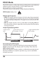
HOLD Mode
The HOLD mode is a safety state during configuration and calibration.
Output current is frozen (LAST) or set to a fixed value (FIX).
Alarm and limit contacts are disabled.
The HOLD mode is indicated by orange display backlighting.
HOLD mode, display icon:
Output signal response
• LAST: The output current is frozen at its last value. Recommended
for short configuration procedures. The process should not change
decisively during configuration. Changes are not noticed with this
setting!
• FIX: The output current is set to a value that is noticeably different
from the process value to signal the control system that the device
is being worked at.
Output signal during HOLD:
Output current
[mA]
Output signal for HOLD
FIX setting = 21.0 mA
Output signal for HOLD
LAST setting
21
4
HOLD active
HOLD active
Terminating the HOLD mode
The HOLD mode is ended by switching to measuring mode (hold
meas key depressed). The display reads “Good Bye“, after that, the
HOLD mode is exited.
When the calibration mode is exited, a confirmation prompt ensures
that the installation is ready for operation (e.g.: sensor reinstalled,
located in process).
34
Alarm
External activation of HOLD (SW-A005)
The HOLD mode can be activated from outside by sending a signal to
the HOLD input (e.g. from the process control system).
Power supply
12...24 V AC/DC
HOLD
11
12
input
Process control system
HOLD inactive
HOLD active
0...2 V AC/DC
10...30 V AC/DC
Manual activation of HOLD
The HOLD mode can be activated manually from the HOLD menu. This
allows checking or replacing a sensor, for example, without provoking
unintended reactions of outputs or contacts.
Press meas key to return to selection menu.
Alarm
When an error has occurred, Err xx is displayed immediately.
Only after expiry of a user-defined delay time will the alarm be
registered and entered in the logbook.
During an alarm the display blinks, the display backlighting turns red.
Error messages can also be signaled by a 22 mA output current
(see Configuration).
The alarm contact is activated by alarm and power failure, see also
“Configuration / Alarm Settings“.
2 sec after the failure event is corrected, the alarm status will be
deleted.
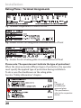
35
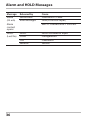
Alarm and HOLD Messages
Message
Alarm
(22 mA)
Alarm
contact
opens
HOLD
(Last/Fix)
36
Released by
Sensocheck
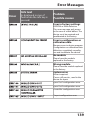
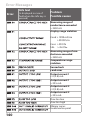
Error Messages
Cause
Polarization / Cable
Flow (CONTROL input)
ERR 10: Conductance > 3500 mS
HOLD
CONF
CAL
SERVICE
HOLD via menu or input
Configuration
Calibration
Service
Alarm and HOLD Messages
Generating a message via the CONTROL input
(min. flow / max. flow)
The CONTROL input can be used for parameter set selection or for
flow measurement (pulse principle), depending on its assignment in
the "Configuration" menu.
When preset to flow measurement
an alarm can be generated when the measured flow exceeds a specified range:
(specify value, default: 5 liters/h)
(specify value, default: 25 liters/h)
CONTROL
Power supply
12...24 V AC/DC
13
12 input
37
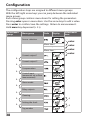
Configuration
The configuration steps are assigned to different menu groups.
With the left/right arrow keys you can jump between the individual
menu groups.
Each menu group contains menu items for setting the parameters.
Pressing enter opens a menu item. Use the arrow keys to edit a value.
Press enter to confirm/save the settings. Return to measurement:
Hold meas key depressed (> 2 s).
Select menu
group
Menu group
Code
Display
Sensor selection
enter
Menu item 1
...
Menu item ...
Current output 1
Select menu
item
enter
enter
enter
Current output 2
Compensation
Control input
(parameter set or flow
measurement)
Alarm mode
Relay outputs
Cleaning
Setting the clock
Tag number
38
Configuration
Parameter set A/B: configurable menu groups
The device provides 2 parameter sets “A“ and “B“. By switching between the parameter sets you can adapt the device to different measurement situations, for example.
Parameter set “B“ only permits setting of process-related parameters.
Menu group
Parameter set A
Parameter set B
Sensor selection
Current output 1
Current output 2
Compensation
Control input
Alarm mode
Relay outputs
Cleaning
Parameter set selection
Setting the clock
Tag number
--Current output 1
Current output 2
Compensation
--Alarm mode
Relay outputs
---------
External switchover of parameter sets A/B
You can switch between parameter sets A and B by applying a signal
).
to the CONTROL input (parameter setting:
Max. 30 V AC/DC
CONTROL
12
13
input
e.g. process control system
Parameter set A active
Parameter set B active
0...2 V AC/DC
10...30 V AC/DC
39
Configuration
Parameter Set A/B
Manual Selection. Signaling via WASH Contact.
Display
Action
Remark
To switch between
parameter sets:
Press meas.
Manual selection of
parameter sets must have
been preset in CONFIG
mode. Default setting is a
fixed parameter set A.
Wrong settings change
the measurement
properties!
PARSET blinks in the
lower line.
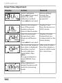
Select parameter set
using and keys
Select
PARSET A / PARSET B
Press enter to
confirm.
Cancel by pressing
meas
Wash
19
R4
20
40
The active parameter set can be
signaled using the WASH contact:
If configured correspondingly,
the WASH contact signals:
“Parameter set A“ (open contact)
“Parameter set B“ (closed contact)
Configuration
Configuration
Choices
Default
Sensor (SENSOR)
*) These sensors appear in the menu selection but can only be used
with a measuring module installed. Stratos Pro A4... MSCONDI is
intended for connecting the SE 670 sensor via RS-485 interface.
It does not provide a measuring module.
For information on retrofitting and the respective costs,
please contact the manufacturer (see back of this manual).
41
Configuration
Configuration
Choices
Default
Output 1 (OUT1)
Output (with Cond only)
Input range: selected CHANNEL
Vertex X :
BEGIN ≤ CORNER X ≤ END (rising)
BEGIN ≥ CORNER X ≥ END (falling)
Input range: selected CHANNEL
Default: 12 mA
Vertex Y:
(0) 4 mA ≤ CORNER Y ≤ 20 mA
Decades
Decades
42
Configuration
Configuration
Choices
Default
Output 2 (OUT2)
... other steps like output 1
Temperature compensation (CORRECTION)
I-INPUT (only with TEMP EXT selected – The I-input option must be
enabled via TAN)
Control input (CNTR_IN)
Parameter-set
switchover (PARSET)
or
flow measurement
(FLOW)
12000
pulses/liter
0 ... 20000
pulses/liter
Alarm (ALARM)
*) These menu items appear only if selected.
**)Hysteresis fixed at 5% of threshold value
43
Configuration
Configuration
Choices
Switching outputs (Rel1/Rel2)
Selected in text line
Within meas. range
0 ... 50 % full scale
Within meas. range
0 ... 50 % full scale
Within meas. range
0 ... 50 % full scale
44
Default
Configuration
Configuration
Choices
Default
Cleaning contact (WASH)
Selected in text line
Parameter set (PARSET)
Select fixed parameter set
(A) or switch between A/B
via control input or manually in measuring mode
(fixed parameter
set A)
Real-time clock (CLOCK)
Tag number (TAG)
(Input in text line)
___
45
Configuration (Original for Copy)
Two complete parameter sets are stored in the EEPROM.
As delivered, the two sets are identical but can be edited.
Note:
Fill in your configuration data on the following pages or use them as
original for copy.
46
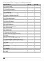
Configuration (Original for Copy)
Parameter
Parameter set A
Parameter set B
SNS: Sensor type
SNS: RTD type
SNS: Cell factor
SNS: Transfer ratio
SNS: Measuring mode
SNS: Measuring range
SNS: Concentration
determination
SNS: Temperature unit
SNS: CIP counter
SNS: SIP counter
OT1: Current range
OT1: Process variable
OT1: Lin/bilin/log output
OT1: Current start
OT1: Current end
OT1: Vertex X (bilinear
curve only)
OT1: Vertex Y (bilinear
curve only)
OT1: Filter time
OT1: 22 mA error current
OT1: HOLD mode
OT1: HOLD-FIX current
*) These parameters cannot be adjusted in parameter set B,
the values are the same as in parameter set A.
47
(Original for Copy) Configuration
Parameter
OT2: Current range
OT2: Process variable
OT2: Lin/bilin/log output
OT2: Current start
OT2: Current end
OT2: Vertex X (bilinear curve only)
OT2: Vertex Y (bilinear curve only)
OT2: Filter time
OT2: 22 mA error current
OT2: HOLD mode
OT2: HOLD-FIX current
COR: TC SELECT
COR: Temp coefficient
COR: Reference temperature
COR: Current range
COR: Current start
COR: Current end
IN: Parameter set A/B or flow
IN: (Flow meter) Adjusting pulses/liter
ALA: Delay
ALA: Sensocheck on/off
ALA: Flow control FLOW CNTR on/off
ALA: Minimum flow (hysteresis fixed at 5 %)
ALA: Maximum flow (hysteresis fixed at 5 %)
REL: Usage
RL1: Process variable
RL1: Function
RL1: Contact response
RL1: Setpoint
RL1: Hysteresis
RL1: Delay
48
Set A
Set B
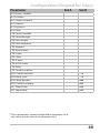
Configuration (Original for Copy)
Parameter
Set A
Set B
RL2: Process variable
RL2: Function
RL2: Contact response
RL2: Setpoint
RL2: Hysteresis
RL2: Delay
CTR: Process variable
CTR: Controller type
CTR: Pulse length
CTR: Pulse frequency
CTR: Setpoint
CTR: Neutral zone
CTR: P gain
CTR: I time
CTR: D time
CTR: HOLD mode
CTR: Delay
CTR: Contact response
WSH: Contact function
WSH: Wash cycle
WSH: Wash duration
WSH: Contact response
CLK: Time & Date
TAG: Tag number
*) These parameters cannot be adjusted in parameter set B,
the values are the same as in parameter set A.
49
Configuration
Sensor
Select: Sensor type, temperature probe, cell factor, transfer ratio,
measuring mode, range
1) Press menu key.
2) Select CONF using keys, press enter.
3) Select parameter set using , press enter.
4) Select SENSOR menu using keys, press
enter.
5) All items of this menu group are indicated by
the “SNS:” code.
Press enter to select menu,
edit using arrow keys (see next page).
Confirm (and proceed) using enter.
6) Exit: Press meas key until the [meas] mode
indicator is displayed.
5
Sensor type
Temperature probe
Cell factor
Transfer ratio
Measuring mode
Measuring range
Concentration determination
5
Temperature unit
Cleaning cycles
Sterilization cycles
6
50
Configuration
5
Menu item
Action
Sensor type
Select sensor type SE 670
using keys (default
setting).
Choices
Press enter to confirm.
Temperature probe
Only with OTHER:
Select type of temperature probe using
keys.
Press enter to confirm.
Cell factor
Enter cell factor using
keys.
Press enter to confirm.
Transfer ratio
Measuring mode
Enter transfer ratio using
keys.
Press enter to confirm.
Select desired measuring
mode using keys.
Press enter to confirm.
Measuring range
For cond measurement
only
Select desired range
using keys.
Press enter to confirm.
51
Configuration
Sensor
Select: Concentration determination, temperature unit
1) Press menu key.
2) Select CONF using keys, press enter.
3) Select parameter set using , press enter.
4) Select SENSOR menu using keys, press
enter.
5) All items of this menu group are indicated by
the “SNS:” code.
Press enter to select menu,
edit using arrow keys (see next page).
Confirm (and proceed) using enter.
6) Exit: Press meas key until the [meas] mode
indicator is displayed.
Sensor type
Temperature probe
Cell factor
Transfer ratio
Measuring mode
Measuring range
Concentration determination
5
Temperature unit
Cleaning cycles
Sterilization cycles
6
52
5
Configuration
5
Menu item
Action
Concentration
determination
For conc measurement
only
Choices
Select desired concentration solution using
(see appendix for ranges).
Press enter to confirm.
Temperature unit
Select °C or °F using
keys.
Press enter to confirm.
53
Configuration
Sensor (ISM only)
Adjust: Cleaning cycles, sterilization cycles
1) Press menu key.
2) Select CONF using keys, press enter.
3) Select parameter set using , press enter.
4) Select SENSOR menu using keys, press
enter.
5) All items of this menu group are indicated by
the “SNS:” code.
Press enter to select menu,
edit using arrow keys (see next page).
Confirm (and proceed) using enter.
6) Exit: Press meas key until the [meas] mode
indicator is displayed.
Select sensor type
Select temp probe
Select cell factor
Select transfer ratio
Select measuring mode
Select range
Concentration determination
5
Temperature unit
Cleaning cycles
Sterilization cycles
6
54
5
Configuration
5
Menu item
Action
Choices
CIP / SIP (ISM only)
Cleaning cycles
on/off
Select ON or OFF using
keys.
Activates/deactivates logging in extended logbook
Press enter to confirm.
Sterilization cycles
on/off
Select ON or OFF using
keys.
Activates/deactivates logging in extended logbook
Press enter to confirm.
The cleaning and sterilization cycles are logged to measure the load
on the sensor.
Suitable for biochemical applications (process temp approx. 0 ... 50 °C,
CIP temp > 55 °C, SIP temp > 115 °C).
Please note:
A CIP or SIP cycle is only entered into the logbook 2 hours after the
start to ensure that the cycle is complete.
55
Configuration
Current Output 1
Output current range. Linear/Logarithmic. Current start.
1) Press menu key.
2) Select CONF using keys, press enter.
3) Select parameter set using , press enter.
4) Select OUT1 menu using keys, press
enter.
5) All items of this menu group are indicated by
the “OT1:” code.
Press enter to select menu,
edit using arrow keys (see next page).
Confirm (and proceed) using enter.
6) Exit: Press meas key until the [meas] mode
indicator is displayed.
5
5
Current range
Process variable
LIN/biLIN/LOG output*
Current start
Current end
Time averaging filter
Output current during error
message
Output current during HOLD
Output current for HOLD FIX
6
*) for Cond only
56
Configuration
5
Menu item
Action
Remark
Current range
Select 4-20 mA or
0-20 mA range using
keys.
Press enter to confirm.
Process variable
Select using keys:
Cond: Conductivity
TMP: Temperature
Press enter to confirm.
Then select characteristic
(LIN/biLIN/LOG).
Selectable decades with
logarithmic setting (LOG):
Current start
Modify digit using
keys,
select next digit using
keys.
Press enter to confirm.
Entered value applies to
selected process variable/
range
If the adjusted range is
exceeded, the device
automatically switches
to the next higher range
(Autorange)
Current end
Enter value using
keys.
Entered value applies to
selected process variable/
range
If the adjusted range is
exceeded, the device
automatically switches
to the next higher range
(Autorange)
Press enter to confirm.
Assignment of measured values: Current start and current end
Example 1: Range 0...200 mS/cm
[mS/cm]
200
Example 2: Range 100...200 mS/cm
Advantage: Higher resolution in range
of interest
[mS/cm]
200
100
0
Output current
4
20 [mA]
100
Output current
4
20 [mA]
57
Configuration
Current Output 1
Output current curve, bilinear
1) Press menu key.
2) Select CONF using keys, press enter.
3) Select parameter set using , press enter.
4) Select OUT1 menu using keys, press
enter.
5) All items of this menu group are indicated by
the “OT1:” code.
Press enter to select menu,
edit using arrow keys (see next page).
Confirm (and proceed) using enter.
6) Exit: Press meas key until the [meas] mode
indicator is displayed.
5
5
6
Current range
Process variable
LIN/biLIN/LOG output*
Current start
Current end
Bilinear: Vertex X
Bilinear: Vertex Y
Time averaging filter
Output current during error
message
Output current during HOLD
Output current for HOLD FIX
*) for Cond only
58
Configuration
5
Menu item
Action
Choices
Output current
curve
Select using keys.
Press enter to confirm.
LIN
Linear characteristic
biLIN
Bilinear curve
LOG
Logarithmic curve
Current start
and current end
Enter value using
keys.
Entered value applies to
selected process variable/
range
If the adjusted range is
exceeded, the device
automatically switches
to the next higher range
(Autorange)
Press enter to confirm.
Bilinear curve:
Vertex X/Y
Enter value using
keys.
Press enter to confirm.
Entered value applies to
selected vertex of bilinear
curve "Corner X“ (process
variable) and "Corner Y
(output current) –
see figure below.
Vertex of bilinear curve
Output current
Example:
Current range 4 ... 20 mA,
Current start: 0 µS/cm
Current end: 200 µS/cm
Vertex:
"CORNER X“: 10 µS/cm (process variable)
"CORNER Y“: 12 mA (output current)
Result: The output current change in the
range 0 ... 10 µS/cm is much greater than
in the range 10 ... 200 µS/cm.
Process variable
59
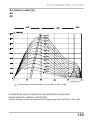
Logarithmic Curve
Nonlinear output current characteristic: allows measurements over several decades,
e.g. measuring very low values with a high resolution and high values with a low
resolution.
Parameters required: Start and end value
Possible start and end values
The start value must be at least one decade lower than the end value.
Start value and end value must be specified in the same units
(either in µS/cm or in S/m, see listing):
0.001 mS/cm
0.01 mS/cm
0.1 mS/m
0.001 S/m
0.01 S/m
0.1 S/m
1.0 S/m
10.0 S/m
100 S/m
The start value
is the next decade value below the lowest measured value.
The end value
is the next decade value above the highest measured value.
The number of decades results from:
Number of decades = log (end value) – log (start value)
The output current value is defined as follows:
Output current =
log(measured value) – log(start value)
Number of decades
Measured
values
Start value
60
End value
Decades
Configuration
5
Menu item
Action
Choices
Logarithmic curve
of output current
Select using keys.
Press enter to confirm.
LOG
Logarithmic curve
biLIN
Bilinear curve
LIN
Linear characteristic
Start value
Enter value using
keys.
Start value of logarithmic
output curve
Press enter to confirm.
End value
Enter value using
keys.
End value of logarithmic
output curve
Press enter to confirm.
Possible start and end values for the logarithmic curve
S/cm:
S/m:
61
Configuration
Current Output 1
Adjusting the time interval of the output filter
1) Press menu key.
2) Select CONF using keys, press enter.
3) Select parameter set using , press enter.
4) Select OUT1 menu using keys, press
enter.
5) All items of this menu group are indicated by
the “OT1:” code.
Press enter to select menu,
edit using arrow keys (see next page).
Confirm (and proceed) using enter.
6) Exit: Press meas key until the [meas] mode
indicator is displayed.
5
5
6
62
Current range
Process variable
LIN/biLIN/LOG output
Current start
Current end
Time averaging filter
Output current during error
message
Output current during HOLD
Output current for HOLD FIX
Configuration
5
Menu item
Action
Time averaging filter
Enter value using
keys.
Choices
Press enter to confirm.
Time averaging filter
To smoothen the current output, a low-pass filter with adjustable filter
time constant can be switched on. When there is a jump at the input
(100 %), the output level is at 63 % after the time interval has been
reached. The time interval can be set from 0 to 120 sec. If the time
interval is set to 0 sec, the current output directly follows the input.
Please note:
The filter only acts on the current output, not on the display or the
limit value!
During HOLD the filter is not applied. This prevents a jump at the
output.
Display
COND
0/4-20 mA
Time interval 0...120 s
TMP
Time interval 0...120 s
63
Configuration
Current Output 1
Output current during Error and HOLD
1) Press menu key.
2) Select CONF using keys, press enter.
3) Select parameter set using , press enter.
4) Select OUT1 menu using keys, press
enter.
5) All items of this menu group are indicated by
the “OT1:” code.
Press enter to select menu,
edit using arrow keys (see next page).
Confirm (and proceed) using enter.
6) Exit: Press meas key until the [meas] mode
indicator is displayed.
5
5
6
64
Current range
Process variable
LIN/biLIN/LOG output
Current start
Current end
Time averaging filter
Output current during error
message
Output current during HOLD
Output current for HOLD FIX
Configuration
5
Menu item
Action
Choices
Select ON (22 mA for
Output current
during error message error message) or OFF
using keys.
Press enter to confirm.
Output current
during HOLD
LAST: During HOLD the
last measured value is
maintained at the output.
FIX: During HOLD a value
(to be entered) is maintained at the output.
Select using
Press enter to confirm.
Output current for
HOLD FIX
Only with FIX selected:
Enter current which is to
flow at the output during
HOLD
Enter value using
keys.
Press enter to confirm.
Output signal during HOLD:
Output current
[mA]
Output signal for HOLD
FIX setting = 21.0 mA
Output signal for HOLD
LAST setting
21
4
HOLD active
HOLD active
65
Configuration
Current Output 2
Output current range. Process variable . . .
1) Press menu key.
2) Select CONF using keys, press enter.
3) Select parameter set using , press enter.
4) Select OUT2 menu using keys, press
enter.
5) All items of this menu group are indicated by
the “OT2:” code.
Press enter to select menu,
edit using arrow keys (see next page).
Confirm (and proceed) using enter.
6) Exit: Press meas key until the [meas] mode
indicator is displayed.
5
5
6
66
Current range
Process variable
LIN/biLIN/LOG output
Current start
Current end
Bilinear: Vertex X
Bilinear: Vertex Y
Time averaging filter
Output current during error
message
Output current during HOLD
Output current for HOLD FIX
Configuration
5
Menu item
Action
Current range
Select 4-20 mA or
0-20 mA range using
keys.
Choices
Press enter to confirm.
Process variable
Select using keys:
Cond: Conductivity
TMP: Temperature
Press enter to confirm.
.
.
.
All the following adjustments are made as for current output 1
(see there)!
67
Configuration
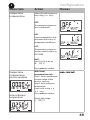
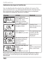
Temperature Compensation
Selecting the compensation method. TC process medium.
1) Press menu key.
2) Select CONF using keys, press enter.
3) Select parameter set using , press enter.
4) Select CORRECTION menu using keys,
press enter.
5) All items of this menu group are indicated by
the “COR:” code.
Press enter to select menu,
edit using arrow keys (see next page).
Confirm (and proceed) using enter.
6) Exit: Press meas key until the [meas] mode
indicator is displayed.
5
5
6
68
Temperature compensation
Current input,
external temp measurement
Current start
Current end
Configuration
5
Menu item
Action
Temperature
compensation
Select desired compensation using keys:
Choices
OFF:
Temperature compensation switched off
LIN:
Linear temperature compensation with entry of
temperature coefficient
nLF:
Temperature compensation for natural waters to
EN 27888
NaCl:
from 0 to 26 % by wt
(0 ... 120 °C)
Press enter to confirm.
Temperature
compensation,
process medium
Enter reference
temperature
With linear
compensation only:
Step 1: Enter temperature
compensation of the
process medium.
Step 2: Enter reference
temperature
Enter value using
keys.
Press enter to confirm.
Permissible range:
0 ... 199.9 °C
69
Configuration
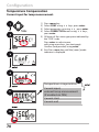
Temperature Compensation
Current input for temp measurement.
1) Press menu key.
2) Select CONF using keys, press enter.
3) Select parameter set using , press enter.
4) Select CORRECTION menu using keys,
press enter.
5) All items of this menu group are indicated by
the “COR:” code.
Press enter to select menu,
edit using arrow keys (see next page).
Confirm (and proceed) using enter.
6) Exit: Press meas key until the [meas] mode
indicator is displayed.
5
5
6
70
Temperature compensation
Current input,
external temp measurement
(if enabled via TAN)
Current start
Current end
Configuration
5
Menu item
Action
Choices
With external temp measurement
(current input enabled / TAN):
Select desired range
Current range
using keys.
Press enter to confirm.
Current start
Modify digit using
keys,
select next digit using
keys.
Input range:
Press enter to confirm.
Current end
Enter value using
keys.
Input range:
Press enter to confirm.
71
Configuration
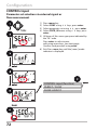
CONTROL Input
Parameter set selection via external signal or
flow measurement
1) Press menu key.
2) Select CONF using keys, press enter.
3) Select parameter set using , press enter.
4) Select CNTR_IN menu using keys, press
enter.
5) All items of this menu group are indicated by
the “IN:” code.
Press enter to select menu,
edit using arrow keys (see next page).
Confirm (and proceed) using enter.
6) Exit: Press meas key until the [meas] mode
indicator is displayed.
CONTROL input (function)
PARSET / FLOW
FLOW: ADJUST
72
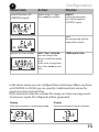
Configuration
5
Menu item
Action
Choices
Select function of
CONTROL input
Select using keys.
Press enter to confirm.
PARSET
(selecting parameter
set A/B via signal at
CONTROL input)
Flow
(for connecting a pulseoutput flow meter)
Adjust to flow meter:
With "Flow" selected,
you must adjust the
device to the flow meter
used.
Enter value using arrow
keys. Press enter to confirm.
12000 pulses/liter
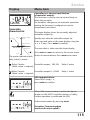
In the alarm menu you can configure flow monitoring. When you have
set CONTROL to FLOW, you can specify 2 additional limit values for
maximum and minimum flow.
If the measured value lies outside this range, an alarm message and a
22-mA error signal (if configured) will be generated.
Display
Flow measurement in measuring mode
Display
Flow measurement (sensor monitor)
73
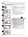
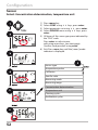
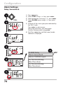
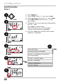
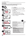
Configuration
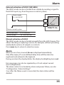
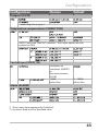
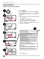
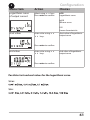
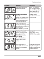
Alarm Settings
Delay. Sensocheck.
1) Press menu key.
2) Select CONF using keys, press enter.
3) Select parameter set using , press enter.
4) Select ALARM menu using keys, press
enter.
5) All items of this menu group are indicated by
the “ALA:” code.
Press enter to select menu,
edit using arrow keys (see next page).
Confirm (and proceed) using enter.
6) Exit: Press meas key until the [meas] mode
indicator is displayed.
ALARM: Delay
Alarm: Sensocheck
Alarm: CONTROL input
For flow monitoring:
Max. flow alarm
For flow monitoring:
Min. flow alarm
74
Configuration
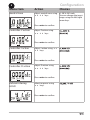
5
Menu item
Action
Delay
Enter value using
keys.
Press enter to confirm.
Sensocheck
Select Sensocheck
(continuous monitoring
of sensor).
Select ON or OFF using
keys.
Press enter to confirm
(At the same time,
Sensoface is activated.
With OFF, Sensoface is
also switched off.)
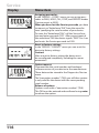
Alarm
R3
Choices
Alarm Contact
The alarm contact is closed during normal
17 operation (N/C).
It opens in the case of alarm or power outage.
As a result, a failure message is provided even
18
in the case of line breakage (fail-safe behavior).
For contact ratings, see Specifications.
Error messages can also be signaled by a 22 mA output current
(see Error messages and Configuration Output 1/Output 2).
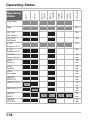
Operating behavior of the alarm contact: see Operating States table.
The alarm delay time delays the color change of the display backlighting to red, the 22 mA signal (if configured), and the alarm contact
switching.
75
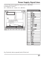
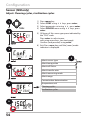
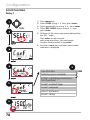
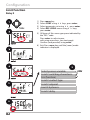
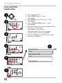
Configuration
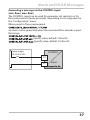
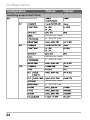
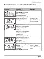
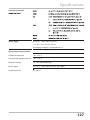
Alarm Settings
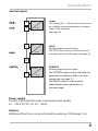
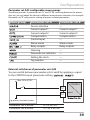
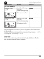
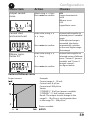
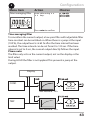
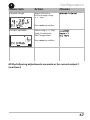
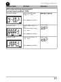
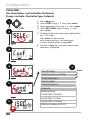
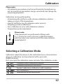
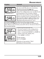
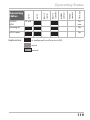
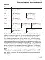
CONTROL input (FLOW MIN, FLOW MAX)
1) Press menu key.
2) Select CONF using keys, press enter.
3) Select parameter set using , press enter.
4) Select ALARM menu using keys, press
enter.
5) All items of this menu group are indicated by
the “ALA:” code.
Press enter to select menu,
edit using arrow keys (see next page).
Confirm (and proceed) using enter.
6) Exit: Press meas key until the [meas] mode
indicator is displayed.
ALARM: Delay
Alarm: Sensocheck
Alarm: CONTROL input
For flow monitoring:
Max. flow alarm
For flow monitoring:
Min. flow alarm
76
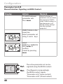
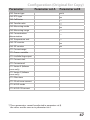
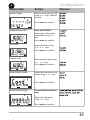
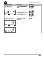
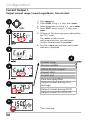
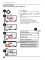
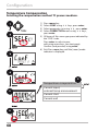
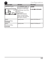
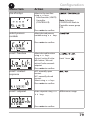
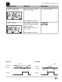
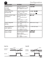
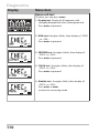
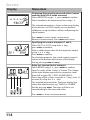
Configuration
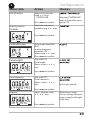
5
Menu item
Action
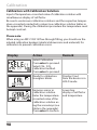
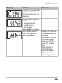
Choices
CONTROL input
The CONTROL input can
generate an alarm when
assigned to FLOW (flow
monitoring) in the CONF
menu:
FLOW CNTR
Flow measurement:
allows monitoring the
minimum and maximum
flow (pulse counter)
Alarm
Minimum flow
Specify value
Default: 05.00 liters/h
Alarm
Maximum flow
Specify value
Default: 25.00 liters/h
FLOW MIN
FLOW MIN
77
Configuration
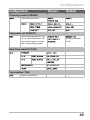
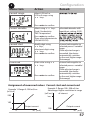
Limit Function
Relay 1
1) Press menu key.
2) Select CONF using keys, press enter.
3) Select parameter set using , press enter.
4) Select REL1/REL2 menu using keys,
press enter.
5) All items of this menu group are indicated by
the “RL1:” code.
Press enter to select menu,
edit using arrow keys (see next page).
Confirm (and proceed) using enter.
6) Exit: Press meas key until the [meas] mode
indicator is displayed.
5
5
6
78
Use of relays
Select process variable
Limit 1 switching characteristics (function)
Limit 1 contact type
Limit 1 setpoint
Limit 1 hysteresis
Limit 1 delay
Configuration
5
Menu item
Action
Use of relays
Select in the text line
using keys:
• Limit function (LIMITS)
• Controller
(CONTROLLER)
Press enter to confirm.
Select process
variable
Choices
Note: Selecting
CONTROLLER leads to
Controller menu group
CTR.
Select desired process
variable using keys.
Press enter to confirm.
Limit 1 function
Select desired function
using keys.
LoLevel: active if value
falls below / HiLevel:
active if value exceeds
setpoint
Press enter to confirm.
Limit 1 contact
response
N/O: normally open
contact
N/C: normally closed
contact
Select using keys.
Press enter to confirm.
Limit 1 setpoint
Enter setpoint using
keys.
Limit 1 icon:
Within meas. range
Press enter to confirm.
79
Configuration
Limit Function
Relay 1
1) Press menu key.
2) Select CONF using keys, press enter.
3) Select parameter set using , press enter.
4) Select REL1/REL2 menu using keys,
press enter.
5) All items of this menu group are indicated by
the “RL1:” code.
Press enter to select menu,
edit using arrow keys (see next page).
Confirm (and proceed) using enter.
6) Exit: Press meas key until the [meas] mode
indicator is displayed.
5
5
6
80
Use of relays
Select process variable
Limit 1 switching characteristics (function)
Limit 1 contact type
Limit 1 setpoint
Limit 1 hysteresis
Limit 1 delay
Configuration
5
Menu item
Action
Choices
Limit 1 hysteresis
Select hysteresis using
keys.
0 ... 50 % full scale
Press enter to confirm.
Limit 1 delay
The contact is activated
with delay (deactivated
without delay)
Adjust delay using
keys.
Press enter to confirm.
Limit Lo
Limit Hi
Signal
Signal
Hysteresis +
Setpoint
Setpoint
Hysteresis -
1
Contact
1
Contact
0
0
81
Configuration
Limit Function
Relay 2
1) Press menu key.
2) Select CONF using keys, press enter.
3) Select parameter set using , press enter.
4) Select REL1/REL2 menu using keys,
press enter.
5) All items of this menu group are indicated by
the “RL2:” code.
Press enter to select menu,
edit using arrow keys (see next page).
Confirm (and proceed) using enter.
6) Exit: Press meas key until the [meas] mode
indicator is displayed.
5
5
6
82
Select process variable
Limit 2 switching characteristics (function)
Limit 2 contact type
Limit 2 setpoint
Limit 2 hysteresis
Limit 2 delay
Configuration
5
Menu item
Action
Choices
Select process
variable
(CHANNEL)
Limit 2 function
(FUNCTION)
Select desired process
variable using keys.
Press enter to confirm.
Limit 2 contact type
(CONTACT)
N/O: normally open
contact
N/C: normally closed
contact
Select using keys.
Press enter to confirm.
Limit 2 setpoint
(LEVEL)
Enter setpoint using
keys.
Press enter to confirm.
Within meas. range
Limit 2 hysteresis
(HYSTERESIS)
Select hysteresis using
keys.
Press enter to confirm.
0 ... 50 % full scale
Limit 2 delay
(DELAYTIME)
The contact is activated
with delay (deactivated
without delay)
Adjust delay using
keys.
Press enter to confirm.
Select desired function
using keys.
Press enter to confirm.
Limit Lo
Limit 2 icon:
Limit Hi
Signal
Signal
Hysteresis +
Setpoint
Setpoint
Hysteresis -
1
Contact
1
Contact
0
0
83
84
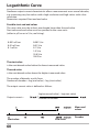
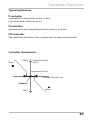
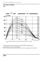
Controller Functions
Typical applications
P controller
Application for integrating control systems
(e.g. closed tank, batch processes).
PI controller
Application for non-integrating control systems (e.g. drains).
PID controller
The additional derivative action compensates for measurement peaks.
Controller characteristic
+100 %
Relay 1
Controller output
Yp [%]
Neutral zone Yp=0
Deviation Xw [mS/cm]
Setpoint
-100 %
Relay 2
85
Controller Functions
Controller equations
Controller output Y =
YP
1
TR
+
P action
+
I action
Proportional action YP
YP = Setpoint - Meas. value
Measuring range
YPdt
* KC
TD
dYP
dt
D action
with:
YP
TN
TD
KC
Proportional action
Reset time [s]
Rate time [s]
Controller gain [%]
Neutral zone (Y=0)
Tolerated deviation from desired value.
With the setting “1 mS/cm”, for example, a deviation of ± 0.5 mS/cm
from the desired value does not activate the controller.
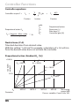
Proportional action (Gradient KC [%])
Controller
output Y
+100 %
KC = 500 %
KC = 200 %
KC = 100 %
50 %
KC = 50 %
Xw
Deviation
86
MR*0.2
MR*0.4
MR*0.6
MR*0.8
Measuring
range (MR)
Process variables: Cond, Conc, SAL
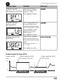
Controller Functions
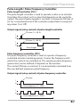
Pulse Length / Pulse Frequency Controller
Pulse length controller (PLC)
The pulse length controller is used to operate a valve as an actuator.
It switches the contact on for a time that depends on the controller
output. The period (pulse length) is constant. A minimum ON time of
0.5 sec is maintained even if the controller output takes corresponding values (Y=0: Off ).
Output signal (relay contact) of pulse length controller
ON time (Y = 20 %)
1
0
1
0
ON time (Y = 80 %)
Pulse length
Pulse frequency controller (PFC)
The pulse frequency controller is used to operate a frequency-
controlled actuator (metering pump). It varies the frequency with
which the contacts are switched on. The maximum pulse frequency
[pulses/min] can be defined. It depends on the actuator.
The contact ON time is constant. It is automatically calculated from
the user-defined maximum pulse frequency:
Output signal (relay contact) of pulse frequency controller
ON time
1
0
Pulse frequency (Y = 20%)
1
0
Pulse frequency (Y = 80%)
87
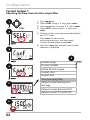
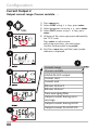
Configuration
Controller
(For description, see Controller Functions)
Process variable. Controller type. Setpoint.
1) Press menu key.
2) Select CONF using keys, press enter.
3) Select parameter set using , press enter.
4) Select REL1/REL2 menu using keys,
press enter.
5) All items of this menu group are indicated by
the “CTR:” code.
Press enter to select menu,
edit using arrow keys (see next page).
Confirm (and proceed) using enter.
6) Exit: Press meas key until the [meas] mode
indicator is displayed.
5
5
6
88
Use of relays
Select process variable
Controller type
Pulse length
Pulse frequency
Setpoint
Neutral zone
Controller: P action
Controller: I action
Controller: D action
Behavior during HOLD
enter
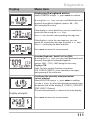
Configuration
5
Menu item
Action
Use of relays
Select in the text line
using keys:
• CONTROLLER
Press enter to confirm.
Select process
variable
Choices
Selecting CONTROLLER
leads to Controller menu
group CTR.
Select desired process
variable using keys.
Press enter to confirm.
Controller type
Pulse length controller
(PLC)
or pulse frequency
controller (PFC)
Select using keys.
Press enter to confirm.
Pulse length
Only with PLC:
Pulse length
Adjust using
keys.
Press enter to confirm.
Pulse frequency
Only with PFC:
Pulse frequency
Adjust using
keys.
(pulses per minute)
Press enter to confirm.
Setpoint
Adjust setpoint using
keys.
Within meas. range
You can change the input
range using the left/right
arrow keys.
Press enter to confirm.
89
Configuration
Controller
(For description, see Controller Functions) Neutral zone.
P, I, D actions. behavior during HOLD, Delay
1) Press menu key.
2) Select CONF using keys, press enter.
3) Select parameter set using , press enter.
4) Select REL1/REL2 menu using keys,
press enter.
5) All items of this menu group are indicated by
the “CTR:” code.
Press enter to select menu,
edit using arrow keys (see next page).
Confirm (and proceed) by pressing enter.
6) Exit: Press meas key until the [meas] mode
indicator is displayed.
5
6
90
Use of relays
Select process variable
Controller type
Pulse length
Pulse frequency
Setpoint
Neutral zone
Controller: P action
Controller: I action
Controller: D action
Behavior during HOLD
Configuration
5
Menu item
Action
Choices
Neutral zone
Adjust neutral zone using 0...50 % full scale
keys.
You can change the input
range using the left/right
arrow keys.
Press enter to confirm.
Controller: P action
Adjust P action using
keys.
Press enter to confirm.
Controller: I action
Adjust I action using
keys.
Press enter to confirm.
Controller: D action
Adjust D action using
keys.
Press enter to confirm.
Behavior during
HOLD
Select response using
keys.
Press enter to confirm.
91
Configuration
WASH Contact
Controlling a rinsing probe or
signaling the parameter set
1) Press menu key.
2) Select CONF using keys,
press enter.
3) Select parameter set A using keys,
press enter.
4) Select WASH menu using keys,
press enter.
5) All items of this menu group are indicated by
the “WSH:” code.
Press enter to select menu,
edit using arrow keys (see next page).
Confirm (and proceed) using enter.
6) End: Press meas key until the [meas] mode
indicator is displayed.
5
5
6
92
Function
Cleaning interval
Cleaning duration
Contact type
Configuration
5
Menu item
Action
Function
Select WASH contact
function using keys.
Press enter to confirm.
Cleaning interval
Choices
WASH: Control of rinsing
probes
With PARSET A/B selected,
the contact signals:
“Parameter set A“
(open contact)
“Parameter set B“
(closed contact)
Only with WASH:
Adjust value using
keys.
Press enter to confirm.
Cleaning duration
Only with WASH:
Adjust value using
keys.
Press enter to confirm.
Contact type
Cleaning
Only with WASH:
N/O: normally open
contact
N/C: normally closed
contact
Select using keys.
Press enter to confirm.
Relax time (approx. 20 s)
Cycle interval
HOLD
93
Configuration
Time and Date
Tag Number
1) Press any arrow key.
2) Select CONF using keys,
press enter.
3) Select parameter set A using keys,
press enter.
4) Select CLOCK or TAG using keys,
press enter.
5) All items of this menu group are indicated by
the “CLK:” or “TAG” code.
Press enter to select menu,
edit using arrow keys (see next page).
Confirm (and proceed) using enter.
6) End: Press meas key until the [meas] mode
indicator is displayed.
5
5
Time format
Time
Day and month
Year
Tag number
6
94
Configuration
Time and Date
Control of the calibration and cleaning cycles is based on the time and
date of the integrated real-time clock.
In measuring mode the time is shown in the lower display.
When using digital sensors, the calibration data is written in the sensor
head.
In addition, the logbook entries (cf Diagnostics) are provided with a
time stamp.
Please note:
• After prolonged power outage (> 5 days) the time display is
replaced by dashes and cannot be used for processing.
Enter the correct time.
• There is no automatic switchover from winter to summer time!
Be sure to manually adjust the time!
Tag Number (“TAG“)
You can enter a designation for the point of measurement (tag
number) in the lower display line. Up to 32 digits are possible.
Pressing meas (repeatedly) in the measuring mode indicates the tag
number.
Being part of the device configuration, the “TAG“ can be read out via
IrDA.
A standardized tag number helps, for example, to correctly re-install a
device after repair.
5
Menu item
Action
Choices
Tag number
Select character using
keys,
select next digit using
keys.
A...Z, 0...9, – + < > ? / @
Press enter to confirm.
The first 10 characters are
seen in the display without scrolling.
95
96
Calibration
Please note:
• All calibration procedures must be performed by trained personnel. Incorrectly set parameters may go unnoticed, but change the
measuring properties.
Calibration can be performed by:
• Determining the cell factor with a known calibration solution
taking account of the temperature
• Input of cell factor (e.g. for ultrapure-water sensors)
• Sampling (product calibration)
• Zero calibration in air or with calibration solution
• Temperature probe adjustment
Please note:
If measurements are performed in fittings with
A < 110 mm, be sure to choose a calibration beaker
with the same cross-section and of the same material
(metal/plastic)!
Selecting a Calibration Mode
Calibration adapts the device to the individual sensor characteristics.
Access to calibration can be protected with a passcode
(SERVICE menu).
First, you open the calibration menu and select the calibration mode:
Calibration with calibration solution
Calibration by entry of cell factor
Product calibration (calibration with sampling)
Zero calibration
Temperature probe adjustment
97
Calibration
Calibration with Calibration Solution
Input of temperature-corrected value of calibration solution with
simultaneous display of cell factor.
Be sure to use known calibration solutions and the respective temperature-corrected conductivity values (see calibration solution tables in
the appendix). During the calibration procedure the temperature must
be kept constant.
Please note:
When using an ARF 210/215 flow-through fitting, you should use the
inluded calibration beakers (identical dimensions and materials) for
calibration to prevent calibration errors.
Display
Action
Select Calibration.
Press enter to proceed.
Select CAL_SOL
calibration method.
Press enter to proceed.
Ready for calibration.
Hourglass blinks.
Immerse sensor in
calibration solution.
Enter the temperaturecorrected value of the
calibration solution using the arrow keys (see
table in the appendix).
Press enter to confirm.
98
Remark
Display (3 sec)
Now the device is in
HOLD mode.
Lower line:
display of cell factor
and temperature
Calibration
Display
Action
Remark
The cell factor and zero
point are displayed.
The “hourglass” icon is
blinking.
Use the arrow keys to
select:
• Repeat (repeat
calibration) or
• Measuring.
Press enter to confirm.
With MEAS selected:
End calibration by
pressing enter.
Display of measured
variable, Sensoface
is active.
After end of calibration, the outputs
remain in HOLD
mode for a short
time.
After display of
GOOD BYE, the
device automatically returns to
measuring mode.
99
Calibration
Product Calibration
(Calibration by sampling)
For product calibration, the uncompensated conductivity (mS/cm,
S/m) is used. During product calibration the sensor remains in the
process. The measurement process is only interrupted briefly.
Procedure:
1)The sample is measured in the lab or directly on the site using a
portable meter. To ensure an exact calibration, sample temperature
and process temperature should be the same.
During sampling the device saves the currently measured value
and then returns to measuring mode. Then, the “calibration“ mode
indicator blinks.
2)In the second step you enter the measured sample value in the
device. From the difference between the stored measured value and
entered sample value, the device calculates the new cell factor.
If the sample is invalid, you can take over the value stored during
sampling. In that case the old calibration values are stored.
Afterwards, you can start a new product calibration.
Display
Action
Select Calibration.
Press enter to proceed.
Select P_CAL
calibration method.
Press enter to proceed.
Ready for calibration.
Hourglass blinks.
Take sample and save
value.
Press enter to proceed.
100
Remark
Display (3 sec)
Now the device is in
HOLD mode.
Now the sample can
be measured in the
lab.
Calibration
Display
Action
Remark
The device returns to
measuring mode.
From the blinking
CAL mode indicator
you see that product
calibration has not
been terminated.
Product calibration
Display (3 sec)
step 2:
Now the device is in
When the sample value HOLD mode.
has been determined,
open the product calibration once more
The stored value is
displayed (blinking) and
can be overwritten with
the lab value.
Press enter to proceed.
Display of new cell
factor and zero point
(based on 25°C).
Sensoface is active.
Press enter.
To end calibration:
Select MEAS, then
enter
To repeat
calibration: Select
REPEAT, then enter
After calibration is
ended, the device will
switch to measuring
mode.
After end of calibration, the outputs remain in HOLD mode
for a short time.
101
Calibration
Calibration by Input of Cell Factor
You can directly enter the value for the cell factor of a sensor. This
value must be known, e.g. determined beforehand in the laboratory.
The selected process variable and the temperature are displayed.
This method is suitable for all process variables.
Display
Action
Select Calibration.
Press enter to proceed.
Select CAL_CELL
calibration method.
Press enter to proceed.
Ready for calibration.
Hourglass blinks.
Enter cell factor.
Press enter to proceed.
Remark
Display (3 sec)
Now the device is in
HOLD mode.
The selected process
variable and the
temperature are
displayed.
The device shows the
calculated cell factor
and zero point
(at 25 °C).
Sensoface is active.
Use the arrow keys to Exit:
select:
HOLD is deactivated
• MEAS (exit)
after a short time.
• REPEAT
Press enter to proceed.
Please refer to the Specifications for the nominal cell factor. When
measuring in a restricted space, the individual cell factor must be
determined.
102
Calibration
Zero Calibration in Air / with Calibration Solution
Display
Action
Select Calibration.
Press enter to proceed.
Select CAL_ZERO
calibration method.
Press enter to proceed.
Ready for calibration.
Hourglass blinks.
Remark
Display (3 sec)
Now the device is
in HOLD mode.
Calibration in air.
Edit digits until the lower
display indicates Zero
Calibration with
solution
Edit digits until the lower
display indicates the
solution value
Press enter to proceed.
The device shows the cell
factor (at 25 °C) and the
zero point.
Sensoface is active.
Use the arrow keys to
select:
• MEAS (exit)
• REPEAT
Press enter to proceed.
Exit:
HOLD is deactivated after a short
time.
103
Temp probe adjustment
Calibration
Temp Probe Adjustment
Display
104
Action
Remark
Select Calibration.
Press enter to proceed.
Select CAL_RTD
calibration method.
Press enter to proceed.
Wrong settings
change the
measurement
properties!
Measure the tempera
ture of the process
medium using an
external thermometer.
Display (3 sec)
Now the device is in
HOLD mode.
Enter the measured
temperature value.
Maximum difference:
10 K.
Press enter to proceed.
Display of actual
temperature (uncompensated) in the
lower display.
The corrected temperature value is displayed.
Sensoface is active.
To end calibration:
Select MEAS, then
enter
To repeat calibration:
Select REPEAT, then
enter
After calibration is
ended, the device will
switch to measuring
mode.
After end of calibration, the outputs remain in HOLD mode
for a short time.
Measurement
Display
Remark
From the configuration or calibration menus,
you can switch the device to measuring
mode by pressing the meas key.
In the measuring mode the main display
shows the configured process variable (Cond
or AM/PM and °F:
or temperature), the secondary display
shows the time and the second configured
process variable (Cond or temperature). The
[meas] mode indicator lights and the active
parameter set (A/B) is indicated. A/B is not
displayed with parameter set “Fix A”.
Pressing the enter key briefly shows the output currents.
By pressing the meas key you can step through the following displays. When no key has been pressed for 60 sec, the device returns to
the standard display.
1)Selecting the parameter set
(if set to “manual“ in the configuration).
Select the desired parameter set using
thearrow keys (PARSET A or PARSET B
blinks in the lower display line).
Press enter to confirm.
Further displays
(each with meas).
2)Display of tag number (“TAG“)
3)Display of time and date
105
Measurement
Display
Remark
With activated controller, you can also step through the following
displays by pressing the meas key. When no key has been pressed
for 60 sec, the device returns to the standard display.
Main display: Controller output Y
Secondary display: Setpoint
Depending on configuration setting:
conductivity or temperature.
Please note:
• After prolonged power outage (> 5 days) the time display is
replaced by dashes and cannot be used for processing.
Enter the correct time.
106
107
Diagnostics (DIAG)
Diagnostics
In the Diagnostics mode you can access the following menus without
interrupting the measurement:
viewing the calibration data
viewing the sensor data
starting a device self-test
viewing the logbook entries
displaying currently measured values
displaying device type, software version, serial number
Access to diagnostics can be protected with a passcode
(SERVICE menu).
Please note:
HOLD is not active during Diagnostics mode!
Action
Key
Remark
Activate
Diagnostics
Press menu key to call the selection
menu.
(Display color changes to turquoise.)
Select DIAG using keys,
press enter to confirm.
Select
diagnostics
option
Use keys to select from:
Exit
108
See next pages for further
proceeding.
meas
Exit by pressing meas.
Diagnostics
Display
Menu item
Displaying the calibration data
Select CALDATA using, press enter to confirm.
Use thekeys to select the desired parameter
from the bottom line of the display
.
The selected parameter is shown in the main display.
Press meas to return to measurement.
109
Diagnostics
Display
Menu item
Device self-test
(To abort, you can press meas.)
1) Display test: Display of all segments with
changing background colors white/green/red.
Press enter to proceed.
2) RAM test: Hourglass blinks, then display of --PASS- or --FAIL-Press enter to proceed.
3) EEPROM test: Hourglass blinks, then display of
--PASS-- or --FAIL-Press enter to proceed.
4) FLASH test: Hourglass blinks, then display of
--PASS-- or --FAIL-Press enter to proceed.
5) Module test: Hourglass blinks, then display of
--PASS-- or --FAIL-Press enter or meas
to return to measuring mode.
110
Diagnostics
Display
Menu item
Displaying the logbook entries
Select LOGBOOK using, press enter to confirm.
By using the keys, you can scroll backwards and
forwards through the logbook (entries -00-...-99-),
-00- being the last entry.
If the display is set to date/time, you can search for a
particular date using the keys.
Pressto view the corresponding message text.
If the display is set to the message text, you can
search for a particular message using the keys.
Pressto display the date and time.
Press meas to return to measurement.
Extended logbook / Audit Trail (via TAN)
By using the keys, you can scroll backwards and
forwards through the extended logbook
(entries -000-...-199-), -000- being the last entry.
Display: CFR
Audit Trail also records function activations
(CAL CONFIG SERVICE), some Sensoface messages,
and opening of the enclosure.
Display example:
Displaying the currently measured values
(sensor monitor)
Select MONITOR using, press enter to confirm.
Use thekeys to select the desired parameter from
the bottom line of the display (R_COND G_COND RTD
TEMP I-INPUT (Option)).
The selected parameter is shown in the main display.
Press meas to return to measurement.
111
Diagnostics
Display
Menu item
Version
Here, you find the data you require for requesting a
device-specific Option.
Display of device type, software/hardware version,
and serial number for all device components.
Use the keys to switch between software and
hardware version. Press enter to proceed to next
device component.
112
Service (SERVICE) A
Service
In the Service mode you can access the following menus:
Displaying currently measured values
MONITOR
OUT1
Testing current output 1
OUT2
Testing current output 2
RELAY
Testing the function of the 4 relays
CONTROL
Testing the controller function
IRDA
Activating and communicating via the IrDA interface
CODES
Assigning and editing passcodes
DEFAULT
Resetting the device to factory settings
OPTION
Enabling options via TAN.
Please note:
HOLD is active during Service mode!
Action
Key/Display
Remark
Activate
Service
Press menu key to call the selection
menu.
Select SERVICE using keys,
press enter to confirm.
Passcode
Enter passcode “5555“ for service
mode using the keys.
Press enter to confirm.
Display
Exit
In service mode the following icons
are displayed:
• HOLD triangle
• Service (wrench)
meas
Exit by pressing meas.
113
Service
Display
Menu item
Displaying the currently measured values (sensor
monitor) with HOLD mode activated:
Select MONITOR using, press enter to confirm.
Select variable in the bottom text line using.
The selected parameter is shown in the main display.
As the device is in HOLD mode, you can perform
validations using simulators without influencing the
signal outputs.
Press meas to return to the service menu.
Return to measurement: Press meas once more.
Specifying the current at outputs 1 and 2:
Select OUT1 or OUT2 using thekeys,
press enter to confirm.
Enter a valid current value for the respective output
using keys.
Press enter to confirm.
For checking purposes, the actual output current is
shown in the bottom right corner of the display.
Exit by pressing enter or meas.
Relay test (manual test of contacts):
Select RELAIS using, press enter to confirm.
Now the status of the 4 relays is “frozen“. The 4 digits
of the main display represent the respective states
(from left to right: REL1, REL2, ALARM, WASH).
Select one of the 4 relays using the keys, close (1)
or open (0) using the keys.
The selected position blinks. The lower display line
shows the relay function, e.g. “WASH” or “ALARM”.
End by pressing enter. The relays will be re-set
corresponding to the measured value.
Press meas to return to measurement.
114
Service
Display
Menu item
Controller test (manual specification
of controller output):
This function is used to start up control loops or
check the actuators.
For bumpless changeover to automatic operation
(exiting this function), configure an I-action
component (reset time).
Controller
characteristic
+100 %
Relay 1
The lower display shows the currently adjusted
controller output Yp.
Controller output
Yp [%]
Neutral zone Yp=0
Setpoint
-100 %
Deviation
Xw [mS/cm]
Relay 2
The arrows indicate which
relay (valve) is active:
Specify new value for controller output Yp:
Enter sign and value in the main display using the
keys. Press enter to confirm.
The new value is taken into the lower display.
Press enter or meas to return to the service menu.
Return to measurement: Press meas once more.
Relay 2 active
Controller output –100...0%
(Meas. value > setpoint)
Relay 2 active
Controller output 0...+100% Relay 1 active
(Meas. value < setpoint)
Relay 2 active
IrDA communication:
Select IRDA using,
press enter to confirm.
When IrDA communication is active, the device
remains in the HOLD mode for reasons of safety.
Further operation is performed via IrDA.
End communication by pressing meas.
Exception: Firmware update
(must not be interrupted!)
115
Service
Display
Menu item
Assigning passcodes:
In the “SERVICE - CODES“ menu you can assign passcodes to DIAG, HOLD, CAL, CONF, and SERVICE modes
(Service preset to 5555).
When you have lost the Service passcode, you have
to request an “Ambulance TAN“ from the manufacturer specifying the serial number of your device.
To enter the “Ambulance TAN“, call the Service function and enter passcode 7321. After correct input of
the ambulance TAN the device signals “PASS“ for 4 sec
and resets the Service passcode to 5555.
Reset to factory settings:
In the “SERVICE - DEFAULT“ menu you can reset the
device to factory settings.
Caution!
After a reset to factory setting the device must
be reconfigured completely, including the sensor
parameters!
Option request:
Communicate the serial number and hardware/
software version of your device to the manufacturer.
These data can be viewed in the Diagnostics/Version
menu.
The “transaction number“ (TAN) you will then receive
is only valid for the device with the corresponding
serial number.
Release of options:
Options come with a “transaction number“ (TAN).
This TAN must be entered and confirmed using enter
to release the option.
116
117
Measuring
Time out
WASH
contact
ALARM
contact
REL1/2
(Control)
REL1/2
(Limit)
OUT 2
Operating
status
OUT 1
Operating States
-
Diag
60 s
CAL_SOL
Cal solution
No
CAL_CELL
Cell factor
No
P_CAL
Product cal S1
No
P_CAL
Product cal S2
No
CAL RTD
Temp adjustm.
20
min
CONF
ParSet A
20
min
CONF
ParSet B
20
min
CONF
Passcodes
20
min
SERVICE
MONITOR
20
min
SERVICE OUT 1
20
min
SERVICE OUT 2
20
min
SERVICE
RELAIS
20
min
SERVICE
CONTROL
20
min
118
SERVICE
IRDA
22 mA
Time out
WASH
contact
ALARM
contact
REL1/2
(Control)
REL1/2
(Limit)
OUT 2
Operating
status
OUT 1
Operating States
20
min
Cleaning fct
No
HOLD input
No
Explanation: as configured (Last/Fix or Last/Off )
active
manual
119
Product Line and Accessories
Order Code Stratos Pro A 4...
Example
A
4
4-wire / 20...254 V AC/DC
A
4
0 1
N
Channel 1
- PH
Channel 2
/ 0
B,C,E
Communication
Without (HART retrofittable via TAN) 0
Version number
Version
TAN
A
1
Approvals
General Safety
N
ATEX / IECEX / FM / CSA Zone 2 / Cl 1 Div 2 B
Meas. channel 1 / Meas. channel 2
Memosens pH (ORP)
Memosens pH (ORP) / pH (ORP)
Memosens pH (ORP) / Oxy
Memosens COND
Memosens COND / COND
Memosens Oxy
Dual COND (2x2-electrode, analog)
pH / ORP value (ISM digital: TAN)
Cond, 2-/4-electrode
Conductivity, electrodeless
Oxygen (ISM digital/Traces: TAN)
Digital
Digital
Digital
Digital
Digital
Digital
Module
Module
Module
Module
Module
MSPH
MSPH
MSPH
MSCOND
MSCOND
MSOxy
CC
PH
COND
CONDI
OXY
TAN options
HART
Logbook
Extended logbook (Audit Trail)
Trace oxygen measurement
Current input + 2 digital inputs
ISM digital
SW-A001
SW-A002
SW-A003
SW-A004
SW-A005
SW-A006
Mounting accessories
Pipe-mount kit
Protective hood
Panel-mount kit
ZU 0274
ZU 0737
ZU 0738
120
0
MSPH
MSOXY
0
MSCOND
0
0
0
0
0
0
F
D, F
(A)
(B)
(C)
(D)
(E)
(F)
Specifications
CONDI input
Input for electrodeless conductivity sensor
SE 670
Effective ranges
Conductivity
0.02 ... 2000 mS/cm
Display ranges
Conductivity
0.000 ... 9.999 mS/cm (not with SE 660 / SE 670)
00.00 ... 99.99 mS/cm
000.0 ... 999.9 mS/cm
0000 ... 1999 mS/cm
0.000 ... 9.999 S/cm
00.00 ... 99.99 S/cm
Concentration
0.00 ... 9.99 % / 10.0 ... +100 %
Salinity
0.0 ... 45.0 % (0 ... 35 °C)
Response (T90)
Approx. 1 s
Measurement error 1,2,3)
Depending on Memosens
Temp compensation *)
(OFF)
Without
(LIN)
Linear characteristic 00.00 ... 19.99%/K
(reference temp user-defined)
(NLF)
Natural waters to EN 27888
(reference temp 25 °C)
(NACL)
NaCl from 0 to 26 % by wt (0 ... 120 °C
(reference temp 25°C)
-01- NaCl
0 – 26% by wt (0 °C)
-02- HCl
0 – 18% by wt (-20 °C) ... 0 – 18% by wt (50 °C)
Concentration determination
... 0 – 28% by wt (100 °C)
-03- NaOH
0 – 13% by wt (0 °C)
-04- H2SO4
0 - 26% by wt (-17 °C) ... 0 – 37% by wt (110 °C)
... 0 – 24% by wt (100 °C)
-05- HNO3
0 – 30% by wt (-20 °C) ... 0 – 30% by wt (50 °C)
-06- H2SO4
94 – 99% by wt (-17 °C) ... 89 – 99% by wt (115 °C)
-07- HCl
22 – 39% by wt (-20 °C) ... 22 – 39% by wt (50 °C)
-08- HNO3
35 – 96% by wt (-20 °C) ... 35 – 96% by wt (50 °C)
-09- H2SO4
28 – 88% by wt (-17 °C) ... 39 – 88% by wt (115 °C)
-10- NaOH
15 – 50% by wt (0 °C) ... 35 – 50% by wt (100 °C)
121
Specifications
Sensor standardization
Input of cell factor with simultaneous display of selected process
variable and temperature
Input of calibration solution conductivity with simultaneous display of
cell factor
Product calibration for conductivity
Zero adjustment
Temperature probe adjustment
Permissible cell factor
00.100 ... 19.9999 cm-1
Permissible transfer ratio
010.0 ... 199.99 cm-1
Permissible zero offset
± 0.5 mS
Sensocheck
Monitoring of primary and secondary coils and lines for open circuit and
of primary coil and lines for short circuit
Delay
Approx. 30 s
Sensoface
Provides information on the sensor condition (zero point, Sensocheck)
Sensor monitor
Direct display of measured values from sensor for validation
(resistance/temperature)
Calibration data
Calibration date, cell factor
122
Specifications
I input (TAN)
Current input 0/4 ... 20 mA / 50 Ω for external temperature signal
Start/end of scale
Configurable –50 ... +250 °C / –58 ... +482 °F
Characteristic
Linear
Measurement error 1.3)
< 1% current value + 0.1 mA
HOLD input
Galvanically separated (OPTO coupler)
Function
Switches device to HOLD mode
Switching voltage
0 ... 2 V (AC/DC)
HOLD inactive
10 ... 30 V (AC/DC)
HOLD active
CONTROL input
Galvanically separated (OPTO coupler)
Function
Selecting parameter set A/B or flow measurement
Parameter set A/B
Control input
FLOW
Pulse input for flow measurement 0 ... 100 pulses/s
Message
via 22 mA, alarm contact or limit contacts
Display
00.0 … 99.9 l/h
Output 1
0/4 ... 20 mA, max. 10 V, floating (galv. connected to output 2)
Process variable *
Conductivity, resistivity, concentration, salinity, or temperature
Characteristic
Linear, bilinear or logarithmic
Overrange *
22 mA in the case of error messages
Output filter *
PT1 filter, time constant 0 ... 120 s
Measurement error 1)
< 0.25 % current value + 0.025 mA
Start/end of scale *
Configurable within selected range
Bilinear: Vertex X/Y *
Configurable within selected range
Minimum span
LIN
5 % of selected range
LOG
1 decade
0 ... 2 V (AC/DC)
10 ... 30 V (AC/DC)
Parameter set A
Parameter set B
123
Specifications
Output 2
0/4 ... 20 mA, max. 10 V, floating (galv. connected to output 1)
Process variable *
Conductivity, resistivity, concentration, salinity, or temperature
Characteristic
Linear, bilinear or logarithmic
Overrange *
22 mA in the case of error messages
Output filter *
PT1 filter, time constant 0 ... 120 s
Measurement error 1)
< 0.25 % current value + 0.025 mA
Start/end of scale *
Configurable within selected range
Bilinear: Vertex X/Y *
Configurable within selected range
Minimum span
LIN
5 % of selected range
LOG
1 decade
Alarm contact
Relay contact, floating
Contact ratings
AC
< 250 V / < 3 A / < 750 VA
DC
< 30 V / < 3 A / < 90 W
Contact response
N/C (fail-safe type)
Response delay
0000 ... 0600 s
Wash contact
Relay contact, floating
For controlling a cleaning system
Contact ratings
AC
< 250 V / < 3 A / < 750 VA
DC
< 30 V / < 3 A / < 90 W
Contact response *
N/C or N/O
Interval *
000.0 ... 999.9 h (000.0 h = cleaning function switched off )
Cleaning duration
*
0000 ... 1999 s
or
Parameter set A/B
For signaling parameter set A/B
Contact ratings
AC
< 250 V / < 3 A / < 750 VA
DC
< 30 V / < 3 A / < 90 W
Contact open:
Parameter set A active
Contact closed:
Parameter set B active
Contact response *
124
Specifications
Limit values Rel1/Rel2
Contact ratings
Rel1/Rel2 contacts, floating, but inter-connected
AC
< 250 V / < 3 A / < 750 VA
DC
< 30 V / < 3 A / < 90 W
Contact response *
N/C or N/O
Response delay *
0000 ... 9999 s
Setpoints *
As desired within range
Hysteresis *
User-defined
PID process controller
Output via Rel1/Rel2 relay contacts (see limit values)
Setpoint specification*
Within selected range
Neutral zone *
Max. 50 % of selected range
Proportional action*
Controller gain
Kp: 0010 ... 9999 %
Integral action*
Reset time
Tr: 0000 ... 9999 s (0000 s = no integral action)
Derivative action*
Rate time
Td: 0000 ... 9999 s (0000 s = no derivative action)
Controller type *
Pulse length controller or pulse frequency controller
Pulse period *
0001 ... 0600 s, min. ON time 0.5 s (pulse length controller)
Max. pulse frequency*
0001 ... 0180 min–1 (pulse frequency controller)
Real-time clock
Different time and date formats selectable
Power reserve
> 5 days
Display
LC display, 7-segment with icons, colored backlighting
Main display
Character height approx. 22 mm, unit symbols approx. 14 mm
Secondary display
Character height approx. 10 mm
Text line
14 characters, 14 segments
Sensoface
3 status indicators (friendly, neutral, sad face)
Mode indicators
meas, cal, conf, diag
Further icons for configuration and messages
Alarm indication
Display blinks, red backlighting
125
Specifications
Keypad
Keys: meas, menu, info, 4 cursor keys, enter
HART communication
HART version 6
Digital communication by FSK modulation of output current 1
Device identification, measured values, status and messages,
parameter setting, calibration, records
Conditions
Output current ≥ 3.8 mA and load resistance ≥ 250 Ω
IrDA interface
Infrared interface for firmware update
FDA 21 CFR Part 11
Access control by editable passcodes
Logbook entry and flag via HART in the case of configuration changes
Message and logbook entry when enclosure is opened
Diagnostics functions
Calibration data
Calibration date, sensor parameters
Device self-test
Display test, automatic memory test (RAM, FLASH, EEPROM),
module test
Logbook
100 events with date and time
Extended logbook (TAN)
Audit Trail: 200 events with date and time
Service functions
Sensor monitor
Display of direct sensor signals
Current source
Current specifiable for output 1 and 2 (00.00 ... 22.00 mA)
Relay test
Manual control of the four switching contacts
Manual controller
Controller output entered directly (start of control process)
IrDA
Activating the IrDA function
Passcodes
Assigning passcodes for menu access
Factory setting
Resetting all parameters to factory setting
TAN
Enabling optionally available additional functions
Data retention
Parameters, calibration data, logbook > 10 years (EEPROM)
EMC
EN 61326-1 (General Requirements)
Emitted interference
Class B (residential area)
Immunity to interference
Industry EN 61326-2-3
126
Specifications
Explosion protection
Power supply
24 (–15%) ... 230 (+10%) V AC/DC4);
< 12 VA, < 4 W AC: 45 ... 65 Hz
Overvoltage category II, protection class II
Nominal operating conditions
Ambient temperature
–20 ... +55 °C
Transport/Storage temperature
–30 ... +70 °C
Relative humidity
10 ... 95% not condensing
Power supply
24 (–15%) ... 230 (+10%) V AC/DC (DC ≤ 80V)
Frequency for AC
45 ... 65 Hz
127
Specifications
Enclosure
Molded enclosure made of glass-reinforced PBT, PC
Mounting
Wall, pipe/post or panel mounting
Color
Gray, RAL 7001
Ingress protection
IP 67, NEMA 4X
Flammability
UL 94 V-0
Dimensions
148 mm x 148 mm x 117 mm
Control panel cutout
138 mm x 138 mm to DIN 43 700
Weight
Approx. 1200 g (1600 g incl. accessories and packaging)
Cable glands
3 knockouts for M20 x 1.5 cable glands
2 knockouts for NPT ½” or rigid metallic conduit
Connections
Terminals, conductor cross-section max. 2.5 mm2
*) User-defined
1) Acc. to EN 60746, at nominal operating conditions
2) ± 1 count
3) Plus sensor error
4) DC ≤ 80 V
128
Calibration Solutions
Potassium Chloride Solutions
(Conductivity in mS/cm)
Temperature
Concentration 1
[˚C]
0.01 mol/l
0.1 mol/l
1 mol/l
0
5
10
15
16
17
18
19
20
21
22
23
24
25
26
27
28
29
30
31
32
33
34
35
36
0.776
0.896
1.020
1.147
1.173
1.199
1.225
1.251
1.278
1.305
1.332
1.359
1.386
1.413
1.441
1.468
1.496
1.524
1.552
1.581
1.609
1.638
1.667
1.696
7.15
8.22
9.33
10.48
10.72
10.95
11.19
11.43
11.67
11.91
12.15
12.39
12.64
12.88
13.13
13.37
13.62
13.87
14.12
14.37
14.62
14.88
15.13
15.39
15.64
65.41
74.14
83.19
92.52
94.41
96.31
98.22
100.14
102.07
104.00
105.94
107.89
109.84
111.80
113.77
115.74
1) Data source: K. H. Hellwege (Editor), H. Landolt, R. Börnstein: Zahlenwerte und
Funktionen ..., volume 2, part. volume 6
129
Calibration Solutions
Sodium Chloride Solutions
(Conductivity in mS/cm)
Temperature
[˚C]
0
1
2
3
4
5
6
7
8
9
10
11
12
13
14
15
16
17
18
19
20
21
22
23
24
25
26
27
28
29
30
31
32
33
34
35
36
Concentration
0.01 mol/l 1)
0.631
0.651
0.671
0.692
0.712
0.733
0.754
0.775
0.796
0.818
0.839
0.861
0.883
0.905
0.927
0.950
0.972
0.995
1.018
1.041
1.064
1.087
1.111
1.135
1.159
1.183
1.207
1.232
1.256
1.281
1.306
1.331
1.357
1.382
1.408
1.434
1.460
0,1 mol/l 1)
5.786
5.965
6.145
6.327
6.510
6.695
6.881
7.068
7.257
7.447
7.638
7.831
8.025
8.221
8.418
8.617
8.816
9.018
9.221
9.425
9.631
9.838
10.047
10.258
10.469
10.683
10.898
11.114
11.332
11.552
11.773
11.995
12.220
12.445
12.673
12.902
13.132
2)
Saturated
134.5
138.6
142.7
146.9
151.2
155.5
159.9
164.3
168.8
173.4
177.9
182.6
187.2
191.9
196.7
201.5
206.3
211.2
216.1
221.0
226.0
231.0
236.1
241.1
246.2
251.3
256.5
261.6
266.9
272.1
277.4
282.7
288.0
293.3
298.7
304.1
309.5
1) Data source: Test solutions calculated according to DIN IEC 746-3
2) Data source: K. H. Hellwege (Editor), H. Landolt, R. Börnstein: Zahlenwerte und
Funktionen ..., volume 2, part. volume 6
130
Concentration Measurement
Ranges
Substance
NaCl
Configuration
HCl
Configuration
NaOH
Configuration
H2SO4
Configuration
HNO3
Configuration
Concentration ranges
0-26% by wt (0°C)
0-26% by wt (100°C)
-010-18% by wt (-20 °C)
0-18% by wt (50 °C)
-02-
22-39% by wt (-20 °C)
22-39% by wt (50°C)
-07-
0-13% by wt (0 °C)
0-24% by wt (100 °C)
-03-
15-50% by wt (0 °C)
35-50% by wt (100°C)
-10-
0-26% by wt (-17 °C) 28-77% by wt (-17°C)
0-37% by wt (110 °C) 39-88% by wt (115°C)
-04-090-30% by wt (-20°C)
0-30% by wt (50°C)
-05-
94-99% by wt (-17°C)
89-99% by wt (115°C)
-06-
35-96% by wt (-20°C)
35-96% by wt (50°C)
-08-
For the solutions listed above, the device can determine the substance concentration from the measured conductivity and temperature values in % by wt. The measurement error is made up of the
sum of measurements errors during conductivity and temperature
measurement and the accuracy of the concentration curves stored in
the device. We recommend to calibrate the device together with the
sensor, e.g. directly to concentration using the CAL_CELL method. For
exact temperature measurement, you should perform a temperature
probe adjustment. For measuring processes with rapid temperature
changes, a separate temperature probe with fast response should be
used.
When measuring processes such as dilution or intensification of CIP
solutions (Clean-In-Place), it is helpful to switch between the parameter sets for measuring the process medium and for measuring the
CIP solution.
131
Concentration Curves
-01- Sodium chloride solution NaCl
-01-
c [% by wt]
Concentration measurement not possible in this range.
Conductivity versus substance concentration and process
temperature for sodium chloride solution (NaCl)
132
Concentration Curves
-02- Hydrochloric acid HCl
-07-
-02-
-07-
c [% by wt]
Concentration measurement not possible in this range.
Conductivity versus substance concentration and process
temperature for hydrochloric acid (HCl)
Source: Haase/Sauermann/Dücker; Z. phys. Chem. New Edition, Vol. 47 (1965)
133
Concentration Curves
-03- Sodium hydroxide solution NaOH
-10-
-03-
Concentration measurement not possible in this range.
Conductivity versus substance concentration and process
temperature for sodium hydroxide solution (NaOH)
134
-10-
c [% by wt]
Concentration Curves
-04- Sulfuric acid H2SO4
-06-09-
-04-
-06-
-09-
c [% by wt]
Concentration measurement not possible in this range.
Conductivity versus substance concentration and process
temperature for sulfuric acid (H2SO4)
Source: Darling; Journal of Chemical and Engineering Data; Vol.9 No.3, July 1964
135
Concentration Curves
-05- Nitric acid HNO3
-08-
-05-
-08-
c [% by wt]
Concentration measurement not possible in this range.
Conductivity versus substance concentration and process
temperature for nitric acid (HN03)
Source: Haase/Sauermann/Dücker; Z. phys. Chem. New Edition, Vol. 47 (1965)
136
137
Error Handling
Alarm condition:
• The display backlighting turns red
• The alarm icon
is displayed
• The complete measured-value display blinks
• “ERR xxx“ is displayed in the lower menu line
Press the [info] key to view a short error text:
• The error text appears in the lower menu line
• The main display reads “InFo“.
Parameter errors:
Configuration data such as current range, limit values, etc are checked
during the input.
If they are out of range,
• “ERR xxx“ is displayed for 3 sec,
• the display backlighting flashes red,
• the respective maximum or minimum value is shown,
• input must be repeated.
If a faulty parameter arrives through the interface (IrDA, HART),
• an error message will be displayed: “ERR 100...199“
• the faulty parameter can be localized by pressing the [info] key
Calibration errors:
If errors occur during calibration,
• an error message will be displayed
Sensoface:
If the Sensoface becomes sad,
• the display backlighting will turn purple
• the cause can be seen by pressing the info key
• the calibration data can be seen in the Diagnostics menu
138
Error Messages
Info text
Error
(is displayed in case of
fault when the Info key is
pressed)
Problem
Possible causes
Error in factory settings
EEPROM or RAM defective
This error message only occurs
in the case of a total defect. The
device must be repaired and
recalibrated at the factory.
Error in configuration or
calibration data
Memory error in device program
Configuration or calibration data
defective; completely reconfigure and recalibrate the device.
No module
Please have the module
replaced in the factory.
Wrong module
Please have the module replaced
in the factory.
System error
Restart required.
If error still persists, send in the
device for repair.
Span Out1 configuration error
Span Out2 configuration error
Controller configuration error
I-Input configuration error
139
Error Messages
Info text
Error
(is displayed in case of
fault when the Info key is
pressed)
Problem
Possible causes
Measuring range of
conductance exceeded
> 3500 mS
Display range violation
Cond > 1999 mS/cm
> 99.99 S/m
Conc > 99.9 %
SAL > 45.0 ‰
Measuring range of conductance exceeded
> 3500 mS
Temperature range
violation
Sensocheck
Load error
Output current 1
< 0 (3.8) mA
Output current 1
> 20.5 mA
Output current 2
< 0 (3.8) mA
Output current 2
> 20.5 mA
Flow too low
Flow too high
Bilinear curve:
Invalid vertex point
140
Sensoface
(Sensocheck must have been activated during configuration.)
The smiley in the display (Sensoface) alerts to sensor problems
(defective sensor, defective cable, maintenance required). The
permitted calibration ranges and the conditions for a friendly,
neutral, or sad Sensoface are summarized in the following
table. Additional icons refer to the error cause.
Sensocheck
Continuously monitors the sensor and leads for short circuits or open
circuits. Critical values make the Sensoface “sad” and the corresponding icon blinks:
The Sensocheck message is also output as error message Err 15.
The alarm contact is active, the display backlighting turns red, output
current 1 is set to 22 mA (when configured correspondingly).
Sensocheck can be switched off during configuration (then Sensoface
is also disabled).
Exception:
After a calibration a smiley is always displayed for confirmation.
Please note:
The worsening of a Sensoface criterion leads to the devaluation of the
Sensoface indicator (Smiley becomes “sad”). An improvement of the
Sensoface indicator can only take place after calibration or removal of
the sensor defect.
141
Sensoface
Display
142
Problem
Status
Sensor defect
Wrong or defective sensor or
excessive cable capacitance
(see also error message Err 15).
Temperature
Temperature outside range for
TC, conc, sal
FDA 21 CFR Part 11
Conformity with FDA 21 CFR Part 11
In their directive “Title 21 Code of Federal Regulations, 21 CFR Part
11, Electronic Records; Electronic Signatures“ the American health
agency FDA (Food and Drug Administration) regulates the production
and processing of electronic documents for pharmaceutical development and production. This results in requirements for measuring
devices used for corresponding applications. The following features
ensure that the measuring devices of this Series meet the demands of
FDA 21 CFR Part 11:
Electronic Signature – Passcodes
Access to the device functions is regulated and limited by individually
adjustable codes – “Passcodes“ (see SERVICE). This prevents unauthorized modification of device settings or manipulation of the measurement results. Appropriate use of these passcodes makes them suitable
as electronic signature.
Audit Trail
Every (manual) change of device settings can be automatically documented. Each change is tagged with a “Configuration Change Flag“,
which can be interrogated and documented using HART communication. Altered device settings or parameters can also be retrieved and
documented using HART communication.
Extended logbook
Audit Trail also records function activations (CAL, CONFIG, SERVICE),
some Sensoface messages (cal timer, wear) and opening of the
enclosure.
143
Index
21 mA-output signal in HOLD mode 34
22 mA-output signal in case of fault 140
A
“A” is shown on the display 28
Access codes: for operating modes 143
Access codes: setup 116
Accessories 120
Activate rinsing probes, schematic 10
Activate rinsing probes: configuration 92
Alarm and HOLD messages 36
Alarm: contact properties 75
Alarm: current failure 80 f.
Alarm: fault alarm 138
Alarm: flow monitoring 76
Alarm: operating status 35
Alarm: Sensocheck 74 f.
Ambulance TAN, in event of loss of passcode 116
Application in hazardous locations 19
Application, mark rating plate 13
Application, rating plates 20
Approvals, explosion protection, rating plate 13
Approvals, explosion protection, specifications 127
Assembly: enclosure 15
Assembly: options 7
Assembly: panel mounting 18
Assembly: pipe mounting 17
Assembly: wall mounting 16
Audit trail 143
Autorange 57
B
Backlighting 27
C
Calibration data 109
Calibration errors 138
Calibration solutions 129
Calibration: calibration solutions 98
144
Index
Calibration: entry of cell factor 102
Calibration: mode 97
Calibration: operating mode 32
Calibration: product 100
Calibration: zero point 103
CD-ROM 3
Cell factor: input for calibration 102
Certificates: extra booklet 3
Certificates: overview 19
CIP, Clean in Process 55
Commissioning 12
Compensation, introduction 8
Compensation, settings 68
Compulsory marking 13
Concentration curves: -01- sodium chloride solution NaCl 132
Concentration curves: -02- hydrochloric acid HCl 133
Concentration curves: -03- sodium hydroxide solution NaOH 134
Concentration curves: -04- sulfuric acid H2SO4 135
Concentration curves: -05- nitric acid HNO3 136
Concentration measurement, ranges 131
Configuration 32
Configuration: alarm 74
Configuration: cleaning cycles 54
Configuration: concentration solution, selection 52
Configuration: CONTROL input 72
Configuration: controller 88
Configuration: current output 1 56
Configuration: current output 2 66
Configuration: individual data, for copy 46
Configuration: limit function 78
Configuration: menu groups 39
Configuration: output current during Error and HOLD 64
Configuration: overview 41
Configuration: Sensocheck 74
Configuration: sensor 50
Configuration: tag number 94
Configuration: temperature compensation 68
Configuration: time and date 94
145
Index
Configuration: WASH contact 92
Configure output current range 1 56
Configure output current range 2 66
Configure output signal during HOLD 65
Connection example 22
Contact: alarm, configure 75
Contact: alarm, schematic 10
Contact: WASH, configure 92
Contact: WASH, schematic 10
Contacts, service life 24
CONTROL for flow measurement 37
CONTROL for parameter set selection 37
CONTROL input 36
Control inputs: CONTROL 72
Control inputs: HOLD 35
Control inputs: overview 9
CONTROL, floating switching input 72
Controller 85
Controller: characteristic 85
Controller: configuration 88
Controller: controller equations 86
Controller: controller functions 85
Controller: controller test 115
Controller: controller type 89
Controller: manual specification of controller output 115
Controller: neutral zone 91
Controller: pulse frequency 89
Controller: pulse length 89
Controller: setpoint 89
Current output 1 56 f.
Current output 2 66
Current start / end 57
D
Data logger, display entries 111
Data logger, explanation 8
Date and time, display 105
Date and time, use 95
146
Index
Device self-test 110
Diagnostics functions 32
Diagnostics mode 108
Diagnostics: calibration data 109
Diagnostics: device self-test 110
Diagnostics: sensor monitor 111
Diagnostics: software version 112
Dimensions 16
Display backlighting 27
Display colors 31
Display device type 112
Display test 110
Display, icons and colors 27
Display, select main display 30
Disposal 2
Documentation, package contents 3
E
EEPROM test, device self-test 110
Electrical installation 13
Electronic signature 143
Enclosure components 15
Enter cell factor 102
Enter output current value, Service mode 114
Enter values 29
Error handling 138
Error messages 139
Explosion protection 127
Extended logbook, explanation 143
Extended logbook, with TAN 111
F
Fault current value 64
FDA 21 CFR Part 11, requirements for measuring device 143
Fix, output signal in HOLD mode 34
FLASH test 110
FLOW 73
Flow measurement 72
Flow measurement, generate message 37
147
Index
H
HOLD mode 34
HOLD: behavior of output signal 34
HOLD: configure output signal 65
HOLD: end 34
HOLD: external activation 35
HOLD: manual activation 35
HOLD: operating status 34
Hysteresis, application 81
I
Info text 139
Information on installation 19
Install enclosure 7
Installation: Memosens 7
Installation: mounting plan 16
Installation: safety information 13
Installation: terminal assignments 20
Intended use 7
IrDA 26
IrDA: potential errors 138
IrDA: schematic diagram 11
IrDA: select 115
IrDA: specifications 126
K
Keypad 26
L
LAST, output signal in HOLD mode 34
Limit function 1, relay 78
Limit function 2, relay 82
Logarithmic curve 60
Logbook 111
M
Main display 30
Mark type of protection 20
meas, key for function activation 28
Measured values, display 111
148
Index
Measurement 105
Measuring mode selection 50
Measuring mode: change displays 105
Measuring, mode 28
Memosens: cable entry 7
Menu structure 33
Menu structure of configuration 38
Message via CONTROL input 37
Misuse 12
Module test 110
Mounting plan 16
O
Operating mode, selection 29
Operating modes 32
Operating states 118
Option request 116
Option request: requirements 112
Options, overview TAN options 120
Options, release 116
Order code 120
Output filter 62
Output signal during HOLD 34
Overview: device properties 7
Overview: parameter sets 47
Overview: terminal assignments 14
P
Package contents, complete 15
Package contents, documentation 3
Panel mounting 18
Parameter errors 138
Parameter set A/B, introduction 39
Parameter set: configure external switchover 72
Parameter set: display 105
Parameter set: display via WASH contact 40
Parameter set: external switchover 39
Parameter set: individual configuration data 47
Parameter set: switch over manually 40
149
Index
Passcode, configure 116
Passcode, explanation 143
Passcodes 156
PFC (pulse frequency controller) 87
Pin assignments 20
Pipe mounting 17
PLC (pulse length controller) 87
Point of measurement (“TAG”) 95
Power supply 21
Power supply: mains values 9
Product calibration 100
Product line 120
Protective hood 17
Protective wiring 24
Pulse frequency controller (PFC) 87
Pulse length controller (PLC) 87
R
RAM test 110
Rating plates 20
Relay 1 78
Relay 2 82
Relay test 114
Release options 116
Reset to factory settings 116
Return of products under warranty 2
S
Safety information 12
Safety information, separate booklet 3
Selection menu, display menu item 29
Sensocheck: activate 74
Sensocheck: meaning of icons 141
Sensoface: cause of error message 138
Sensoface: meaning of icons 141
Sensor connection, example 22
Sensor monitor: display the currently measured values 111
Sensor monitor: in active HOLD mode 114
Sensor type selection 50
150
Index
Serial number, display 112
Service 32
Service mode 113
Service: controller test 115
Service: factory settings 116
Service: IrDA communication 115
Service: passcode lost 116
Service: passcodes 116
Service: relay test 114
Service: release options 116
Service: sensor monitor 114
Service: specify current outputs 114
Signal colors 27
Signal colors, user prompting 31
Signal lines 21
SIP, sterilization cycles 55
Software version, display 112
Specifications 121
Standard display settings 30
Start-up 12
T
TAG 95
TAN options: release 116
TAN options: required codes 120
Technical data 121
Temp probe adjustment 104
Temperature compensation 69
Temperature detector: adjustment 104
Temperature detector: select type 50
Temperature unit, select 52
Terminal assignments 20
Terminals: properties 13
Time and date 95
Time averaging filter 63
Time: display 105
Trademarks 155
Type of protection: marking 20
151
Index
U
User interface 26
W
Wall mounting 16
Warranty 2
WASH contact: configuration 92
WASH contact: signal parameter set 40
Weather protector 17
Wiring 21
Wiring example: SE 670 (via RS-485) 22
Z
Zero calibration 103
152
Index
153
154
Trademarks
The following names are registered trademarks. For practical reasons
they are shown without trademark symbol in this manual.
Stratos®
Sensocheck®
Sensoface®
Memosens® is a registered trademark of Endress+Hauser Conducta
GmbH and Knick Elektronische Messgeräte GmbH & Co. KG.
HART® is a registered trademark of the HART Communication
Foundation.
155
Passcodes
In the SERVICE – CODES menu you can assign passcodes to protect the
access to certain functions.
Mode of operation
Passcode
Service (SERVICE)
5555
Diagnostics (DIAG)
HOLD mode
Calibration (CAL)
Configuration (CONF)
Knick
Elektronische Messgeräte
GmbH & Co. KG
P.O. Box 37 04 15
D-14134 Berlin
Phone: +49 (0)30 - 801 91 - 0
Fax: +49 (0)30 - 801 91 - 200
Internet: http://www.knick.de
[email protected]
TA-212.035-MS-KNE02
20110301
Software version: 2.x