1
No. CP-SP-1197E
CMQ-V Series
Digital Mass Flow Controller
User's Manual
Communications
Thank you for purchasing the CMQ-V
Series Digital Mass Flow Controller.
This manual contains information for
ensuring correct use of the CMQ-V
Series communication functions.
This manual should be read by those
who design and maintain devices that
use the CMQ-V Series communication
functions. Be sure to keep this manual
nearby for handy reference.
RESTRICTIONS ON USE
This product has been designed, developed and manufactured for general-purpose
application in machinery and equipment.
When using this product in application requiring particular safety, special care should
be taken to implement a fail-safe and/or redundant design concept as well as a
periodic maintenance program.
Do not use this product in applications outlined below requiring particular safety.
• Safety devices for plant worker protection
• Start/stop control devices for transportation and material handling machines
• Aeronautical/aerospace machines
• Control devices for nuclear reactors
Never use this product in applications where human safety may be put at risk.
IMPORTANT
If it is necessary to change the parameters of the CMQ-V Series frequently by
communication, write data at addresses of RAM. The guaranteed data write count at
the EEPROM addresses is limited to 100,000 times.
Note that the data in RAM is cleared, and the data in EEPROM is copied on RAM if the
power supply to the CMQ-V Series interrupted.
NOTICE
Be sure that the user receives this manual before the product is used.
Copying or duplicating this user’s manual in part or in whole is forbidden. The information and specifications in this manual are subject to
change without notice.
Considerable effort has been made to ensure that this manual is free
from inaccuracies and omissions. If you should find an error or omission, please contact Yamatake Corporation.
In no event is Yamatake Corporation liable to anyone for any indirect,
special or consequential damages as a result of using this product.
©2007 Yamatake Corporation ALL RIGHTS RESERVED
TM
TM
TM
Micro Flow , µF , CMQ are trademarks of Yamatake Corporation.
SAFETY PRECAUTIONS
■ About Icons
Safety precautions are for ensuring safe and correct use of this product, and for
preventing injury to the operator and other people or damage to property. You
must observe these safety precautions. The safety precautions described in this
manual are indicated by various icons.
The following describes the icons and their meanings. Be sure to read and
understand the following descriptions before reading this manual.
CAUTION
Cautions are indicated when mishandling this product might
result in minor injury to the user, or only physical damage to
this product.
■ Examples
Triangles warn the user of a possible danger that may be caused by
wrongful operation or misuse of this product.
These icons graphically represent the actual danger. (The example on
the left warns the user of the danger of electrical shock.)
White circles with a diagonal bar notify the user that specific actions are
prohibited to prevent possible danger.
These icons graphically represent the actual prohibited action. (The
example on the left notifies the user that disassembly is prohibited.)
Black filled-in circles instruct the user to carry out a specific obligatory
action to prevent possible danger.
These icons graphically represent the actual action to be carried out.
(The example on the left instructs the user to remove the plug from the
outlet.)
i
CAUTION
Use the CMQ-V Series within the operating ranges recommended in the
specifications of user's manual, CP-SP-1204E and CP-SP-1205E
(temperature, humidity, voltage, vibration, shock, mounting direction,
atmosphere, etc.). Failure to do so might cause malfunction.
Be sure to turn the power off before connecting the controller. Failure
to do so might cause malfunction.
Wire this controller in compliance with the predetermined standards.
Also wire the controller with specified cables and recognized
installation methods.
Failure to do so might cause malfunction.
Make sure that wire scraps, chips or water do not enter inside the case
of the controller. Failure to heed this caution may lead to malfunction.
If there is a risk of a power surge caused by lightning, use Yamatake
Corporation's SurgeNon to prevent possible fire or equipment failure.
Be sure to check that the wiring is correct before turning the power on.
Incorrect wiring could cause damage or malfunction.
Do not disassemble the controller. Doing so might cause malfunction.
ii
The Role of This Manual
Four manuals have been prepared for the CMQ-V Series. Read the manual according to your specific requirements.
The below lists all the manuals that accompany the CMQ-V Series and gives a brief outline of the manual. If you
do not have the required manual, contact Yamatake Corporation or your dealer.
CMQ-V Series Digital Mass Flow Controller
Manual No. CP-SP-1204E
First-time users of the CMQ-V Series, and those in charge of maintenance
or hardware design for incorporating a CMQ-V Series controller in instrumentation should read this manual.
This manual outlines the product, tells how to install, wire, and incorporate
the product into instrumentation, and describes its operation, inspection and
maintenance, troubleshooting, and hardware specifications.
CMQ-V Series Digital Mass Flow Controller (for Hydrogen and Helium Gases)
Manual No. CP-SP-1205E
First-time users of the CMQ-V Series (for hydrogen and helium gases), and
those in charge of maintenance or hardware design for incorporating a
CMQ-V Series controller (For hydrogen and helium gases) in instrumentation should read this manual.
This manual outlines the product, tells how to install, wire, and incorporate
the product into instrumentation, and describes its operation, inspection and
maintenance, troubleshooting, and hardware specifications.
Digital Mass Flow Controller CMQ-V Series: Communications
Manual No.CP-SP-1197E
This manual.
Those using the communications functions of the CMQ-V series should
read this manual.
This manual describes an outline of communications, wiring,
communications procedures, CMQ-V series communications data, troubleshooting, and communications specifications.
MLP100 Loader Package for CMQ-V Series Digital Mass Flow Controller
Manual No. CP-SP-1216E
This manual is supplied with the MLP100 Loader Package.
The manual describes the software used to make various settings for CMQV Series using a personal computer. Personnel in charge of design or setting of a system using CMQ-V Series must thoroughly read this manual.
The manual describes installation of the software into a personal computer,
operation of the personal computer, various functions, and setup procedures.
iii
Organization of This User's Manual
This manual is organized as follows:
Chapter 1. OUTLINE
This chapter briefly describes communication functions of the CMQ-V
Series.
Chapter 2. WIRING
This chapter describes RS-485 wiring methods to make a communication
link between the CMQ-V Series and other instruments.
Chapter 3. SETTING
This chapter describes CMQ-V Series communication settings.
Chapter 4. COMMUNICATION PROCEDURE
This chapter describes communication procedures, message configuration,
data read/write and signal timing operations.
Chapter 5. COMMUNICATION DATA TABLE
This chapter provides various data address tables for communications on
the CMQ-V Series.
Chapter 6. COMMUNICATION PROGRAM FOR MASTER STATION
This chapter gives precautions for programming and an example of a communication program for the CMQ-V Series.
Chapter 7. TROUBLESHOOTING
This chapter describes checkpoints to diagnose failures in CMQ-V Series
communications.
Chapter 8. SPECIFICATIONS
This chapter lists communication specifications for the CMQ-V Series.
APPENDIX
The appendix provides code tables.
Conventions Used in This Manual
The following conventions are used in this manual:
Handling Precautions
: Handling Precautions indicate items that the user should pay attention
to when handling the CMQ-V Series.
Note
: Notes indicate useful information that the user might benefit by
knowing.
(1), (2), (3)
: The numbers with the parenthesis indicate steps in a sequence or
indicate corresponding parts in an explanation.
DISP key
: This indicates a key on the setup display.
iv
Contents
SAFETY PRECAUTIONS
The Role of This Manual
Organization of This User's Manual
Conventions Used in This Manual
Chapter 1.
OUTLINE
■ Features
Chapter 2.
• • • • • • • • • • • • • • • • • • • • • • • • • • • • • • • • • • • • • • • • • • • • • • • • • • • • • • • • • • • • • • • • •
1
WIRING
2-1 RS-485 Connection • • • • • • • • • • • • • • • • • • • • • • • • • • • • • • • • • • • • • • • • • • • • • • • • • • • • • • • • • • 3
2-2 Connector Pin Layout of the CMQ-V Series • • • • • • • • • • • • • • • • • • • • • • • • • • • • • • • • • • 4
Chapter 3.
SETTING
■ Setting method of communication functions • • • • • • • • • • • • • • • • • • • • • • • • • • • • 6
■ Setting items of communication functions • • • • • • • • • • • • • • • • • • • • • • • • • • • • • • • 6
Chapter 4.
COMMUNICATION PROCEDURE
4-1 Outline of Communication • • • • • • • • • • • • • • • • • • • • • • • • • • • • • • • • • • • • • • • • • • • • • • • • • • • 7
■ Communication procedures • • • • • • • • • • • • • • • • • • • • • • • • • • • • • • • • • • • • • • • • • • • • • 7
4-2 Message Structure • • • • • • • • • • • • • • • • • • • • • • • • • • • • • • • • • • • • • • • • • • • • • • • • • • • • • • • • • • • 8
■ Message structure • • • • • • • • • • • • • • • • • • • • • • • • • • • • • • • • • • • • • • • • • • • • • • • • • • • • • • • 8
■ Data link layer • • • • • • • • • • • • • • • • • • • • • • • • • • • • • • • • • • • • • • • • • • • • • • • • • • • • • • • • • • • • 8
■ Application layer • • • • • • • • • • • • • • • • • • • • • • • • • • • • • • • • • • • • • • • • • • • • • • • • • • • • • • • • 10
4-3 Description of Commands • • • • • • • • • • • • • • • • • • • • • • • • • • • • • • • • • • • • • • • • • • • • • • • • • • 11
■ Continuous data read command (RS command) • • • • • • • • • • • • • • • • • • • • • • • 11
■ Continuous data write command (WS command)• • • • • • • • • • • • • • • • • • • • • • • 12
■ Continuous data read command (RD command) • • • • • • • • • • • • • • • • • • • • • • • 13
■ Continuous data write command (WD command) • • • • • • • • • • • • • • • • • • • • • • 14
4-4 Termination Code Table • • • • • • • • • • • • • • • • • • • • • • • • • • • • • • • • • • • • • • • • • • • • • • • • • • • • 15
■ Normal and warning termination• • • • • • • • • • • • • • • • • • • • • • • • • • • • • • • • • • • • • • • • • 15
■ Error termination • • • • • • • • • • • • • • • • • • • • • • • • • • • • • • • • • • • • • • • • • • • • • • • • • • • • • • • • • 15
4-5 Timing Specifications • • • • • • • • • • • • • • • • • • • • • • • • • • • • • • • • • • • • • • • • • • • • • • • • • • • • • • 16
■ Timing specifications for instruction and response message • • • • • • • • • • • • 16
■ RS-485 driver control timing specifications • • • • • • • • • • • • • • • • • • • • • • • • • • • • • • • • 16
■ Other precautions • • • • • • • • • • • • • • • • • • • • • • • • • • • • • • • • • • • • • • • • • • • • • • • • • • • • • • • • 17
v
Chapter 5.
COMMUNICATION DATA TABLE
5-1 Basic Communication Data Processing • • • • • • • • • • • • • • • • • • • • • • • • • • • • • • • • • • • • 18
■ Communication data types and formats • • • • • • • • • • • • • • • • • • • • • • • • • • • • • • • • 18
■ Communication data storage memory • • • • • • • • • • • • • • • • • • • • • • • • • • • • • • • • • • 18
■ Data address• • • • • • • • • • • • • • • • • • • • • • • • • • • • • • • • • • • • • • • • • • • • • • • • • • • • • • • • • • • • 19
■ Data read / write count • • • • • • • • • • • • • • • • • • • • • • • • • • • • • • • • • • • • • • • • • • • • • • • • • • 19
■ Data unit and decimal point position • • • • • • • • • • • • • • • • • • • • • • • • • • • • • • • • • • • 19
5-2 Communication Data Table • • • • • • • • • • • • • • • • • • • • • • • • • • • • • • • • • • • • • • • • • • • • • • • • • 20
■ Device related data • • • • • • • • • • • • • • • • • • • • • • • • • • • • • • • • • • • • • • • • • • • • • • • • • • • • • 20
■ Operating status related data • • • • • • • • • • • • • • • • • • • • • • • • • • • • • • • • • • • • • • • • • • • 21
■ Flow set value • • • • • • • • • • • • • • • • • • • • • • • • • • • • • • • • • • • • • • • • • • • • • • • • • • • • • • • • • • 23
■ Totalized flow related data • • • • • • • • • • • • • • • • • • • • • • • • • • • • • • • • • • • • • • • • • • • • • • 23
■ Function setup related data • • • • • • • • • • • • • • • • • • • • • • • • • • • • • • • • • • • • • • • • • • • • • 24
■ Parameter setup related data • • • • • • • • • • • • • • • • • • • • • • • • • • • • • • • • • • • • • • • • • • • 30
Chapter 6.
COMMUNICATION PROGRAM FOR MASTER STATION
6-1 Precautions for Programming • • • • • • • • • • • • • • • • • • • • • • • • • • • • • • • • • • • • • • • • • • • • • • 32
6-2 Examples of Communication Program • • • • • • • • • • • • • • • • • • • • • • • • • • • • • • • • • • • • • 33
■ Before executing the program • • • • • • • • • • • • • • • • • • • • • • • • • • • • • • • • • • • • • • • • • • 33
■ Executing the program • • • • • • • • • • • • • • • • • • • • • • • • • • • • • • • • • • • • • • • • • • • • • • • • • 33
■ Data read/write sample program • • • • • • • • • • • • • • • • • • • • • • • • • • • • • • • • • • • • • • • • 34
Chapter 7.
TROUBLESHOOTING
■ Check items in case communication is disabled
Chapter 8.
• • • • • • • • • • • • • • • • • • • • • • •
39
SPECIFICATIONS
■ RS-485 specifications • • • • • • • • • • • • • • • • • • • • • • • • • • • • • • • • • • • • • • • • • • • • • • • • • • • 40
APPENDIX
■ Code table • • • • • • • • • • • • • • • • • • • • • • • • • • • • • • • • • • • • • • • • • • • • • • • • • • • • • • • • • • • • • • 41
■ Connection with CMC10L • • • • • • • • • • • • • • • • • • • • • • • • • • • • • • • • • • • • • • • • • • • • • • • 42
vi
Chapter 1.
OUTLINE
If the optional model is provided with the RS-485 communications function, communication with a PC, PLC or
other host devices are available using a user-configured program.
The communication protocol can be selected from the Controller Peripheral Link (CPL) communications
(Yamatake's host communication protocol). This chapter describes the CPL communications.
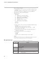
■ Features
The features of the CMQ-V's communications function are as follows:
• Up to 31 units can be connected to a single master station as a host device.
• When the communication specifications of the host device conform to the RS232C interface, the communication converter CMC10L (sold separately) is
required. The CMC10L allows the conversion between RS-232C and RS-485.
• Almost all of the device parameters can be communicated.
For details on communication parameters, refer to;
Chapter 5, COMMUNICATION DATA TABLE.
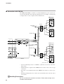
RS-485 connection example
Master station
RS-232C
RS-232C/RS-485 converter
RS-485 (3-wire system)
Slave station
(CMQ-V series, etc)
Connection between master station and slave station
1
Chapter 2.
WIRING
CAUTION
Use the CMQ-V Series within the operating ranges recommended in the
specifications of user's manual, CP-SP-1204E and CP-SP-1205E
(temperature, humidity, voltage, vibration, shock, mounting direction,
atmosphere, etc.). Failure to do so might cause malfunction.
Be sure to turn the power off before connecting the controller. Failure to do so
might cause malfunction.
Wire this controller in compliance with the predetermined standards. Also
wire the controller with specified cables and recognized installation methods.
Failure to do so might cause malfunction.
Make sure that wire scraps, chips or water do not enter inside the case of the
controller. Failure to heed this caution may lead to malfunction.
If there is a risk of a power surge caused by lightning, use Yamatake
Corporation's SurgeNon to prevent possible fire or equipment failure.
Be sure to check that the wiring is correct before turning the power on.
Incorrect wiring could cause damage or malfunction.
Do not disassemble the controller. Doing so might cause malfunction.
Handling Precautions
• Wiring way except the RS-485 communications wiring, refer to;
CMQ-V series Digital Mass Flow Controller user's manual No.CP-SP1204E or CMQ-V Series Digital Mass Flow Controller (for Hydrogen and
Helium Gases) user's manual No.CP-SP-1205E.
2
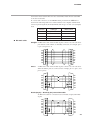
Chapter 2. WIRING
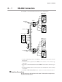
2 - 1
RS-485 Connection
An example of connection methods in such a case is shown below.
CMQ-V Series
(slave station)
7
8
Terminating
resistor
Terminal
block
9
DA
DB
SG
CMQ-V Series
(slave station)
7
8
DA
DB
Shielded cable
9
SG
FG
Master station
DA
DB
CMQ-V Series
(slave station)
SG
FG
7
8
Shielded cable
9
DA
DB
SG
FG
CMQ-V Series
(slave station)
Terminating
resistor
7
Terminal
block
8
9
DA
DB
SG
• Connect terminating resistors of 150Ω±5%, 1/2W min. at each end of the transmission line.
• Terminal block is required for the CMQ-V series because of the connector type
connection.
• The cable to the terminal block from the CMQ-V series must be as short as possible.
• The FG grounding must not be made at the both shielded wire ends but only at
one location.
• Yamatake’s CMC10L001A000 can be used as a converter of the host station.
Handling Precautions
Be sure to connect SG terminals each other. Failure to do so might cause
unstable communications.
3
Chapter 2. WIRING
2 - 2
Connector Pin Layout of the CMQ-V Series
The following shows the connector pin layout of the CMQ-V Series with the communication functions:
● Connector pin layout
20
19
2
1
Mounted connector part number: HIF3BA-20PA-2.54DS
Manufacturer: Hirose Electric Co. Ltd.
Front view
● Mating connector table (All connectors are made by Hirose Electric Co. Ltd.)
Connector type
4
Mating connector part No.
Mating contact
part No.
Contact crimp type
HIF3BA-20D-2.54C
HIF3-2226SCC
Forced pressure
type
HIF3BA-20D-2.54R
Not required
Recommended wire
AWG#22 to #26
(single wire allowed)
AWG#28 (Flat ribbon cable
only)
Chapter 2. WIRING
● Connector signal table
Pin
number
Signal name
Description
Remarks
20
+5V (5mA max.)
5Vdc reference voltage output
5mA max.
19
FLOW OUT
Instantaneous flow rate (PV)
voltage output/ setting flow rate
(SP) output
0 to 5Vdc/ 1 to 5Vdc/ 0 to 20mAdc/
4 to 20mAdc
18
A.GND
Analog ground
Common of analog signals
17
FLOW SP INPUT
Instantaneous flow rate setting
(SP) voltage input
0 to 5Vdc/ 1 to 5Vdc/ 0 to 20mAdc/
4 to 20mAdc
16
MODE INPUT
External 3-stage switching input
3-stage switching input of Open/ GND/ 5V
15
DI3
External contact input 3
Switching input of Open/ GND
14
DI2
External contact input 2
13
DI1
External contact input 1
12
EV2 OUT
Event output 2
11
EV1 OUT
Event output 1
10
ALM OUT
Alarm output
9
SG (D.GND)
RS-485 communications SG
8
DB
RS-485 communications DB
7
DA
RS-485 communications DA
6
SG (D.GND)
RS-485 communications SG
5
TEST
For test
For test (connecting is prohibited)
4
POWER GND
Power supply ground
3
POWER GND
Power supply ground
2
POWER (24V)
Power supply +24Vdc
In order to decrease the voltage drop
caused by wiring resistance, connect each
two wires to the power supply in parallel.
1
POWER (24V)
Power supply +24Vdc
Open collector non-insulated output
Same as the common of digital signal
Same as the common of digital signal
Handling Precautions
• Either pin No. 6 and pin No. 9 is able to connect as SG.
• For details on wiring way, see the CMQ-V Series Digital Mass Flow
Controller user's manual No. CP-SP-1204E or CMQ-V Series Digital Mass
Flow Controller (for Hydrogen and Helium Gases) user's manual No. CPSP-1205E.
5
Chapter 3.
SETTING
Setup the following to operate the communication functions of the CMQ Series:
■ Setting method of communication functions
Follow the following procedure to set the functions:
(1) Display the instantaneous flow rate by pressing the DISP key.
>> “PV” lamp and “L/min” lamp ("mL/min" in MQV9200) start lighting.
(2) Keep pressing the ▼ key and the ENT key at the same time for 3 seconds or
more.
>> The item No. c-0 1 appears on the 7-segment display and mode changes to
the function setup mode.
(3) Select a desired setup item by pressing either ▲ key or ▼ key and then press
the ENT key.
>> The current setting flashes on the 7-segment display.
(4) Select a desired setting by pressing either ▲ key or ▼ key.
(5) After a desired setup mode is selected, confirm it by pressing the ENT key.
>> At this point the setup is updated. (After about one second, the item number
display is returned.)
(6) If other setting items are desired, return to (3) for setting. If no other item is
desired to be set, proceed to the item (7).
(7) Press the DISP key to make the status from the function setup mode to instantaneous flow rate display.
Handling Precautions
• If any key is not pressed for one minute after the function setup mode,
the display automatically returns to the instantaneous flow rate display.
• If the DISP key is pressed without pressing the ENT key after carrying
out the operation in step (4), the setting remains at the previous value
without being update.
■ Setting items of communication functions
Function
Item
Setup item and description
setup item
Remarks
setting
c-3 0
Station address
c-3 1
Transmission speed 0:
1:
2:
3:
4:
c-3 2
Data format
6
Factory
0: Communications function
disabled
1 to 127: Station address
38400bps
19200bps
9600bps
4800bps
2400bps
0: 8 bit data, even parity, 1 stop bit
1: 8 bit data, no parity, 2 stop bits
0
1
0
The communications function does
not work at 0. Set a different address from the slave station.
Chapter 4.
4 - 1
COMMUNICATION PROCEDURE
Outline of Communication
■ Communication procedures
The communication procedure is as follows:
(1)The instruction message is sent from the host device (master station) to one unit
(slave station) to communicate with.
(2)The slave station receives the instruction message, and performs read or write
processing according to the content of the message.
(3)The slave station sends a message corresponding to the processing content as a
response message.
(4)The master station receives the response message.
7
Chapter 4. COMMUNICATION PROCEDURE
4 - 2
Message Structure
■ Message structure
The following shows the message structure:
Messages are broadly classified into two layers; the data link layer and the
application layer.
• Data link layer
This layer contains the basic information required for the communication such
as the destination of the communication message and the check information of
the message.
• Application layer
Data is read and written in this layer. The content of the layer varies
according to the purpose of the message.
Messages comprise parts (1) to (9) as shown in the figure below.
The command (details sent from the master station) and the response (details
returned from the slave station) are stored in the application layer.
02H
58H
03H
0DH 0AH
STX
X
ETX
CR LF
(1)
(2)
(3)
(4)
Data link layer
(5)
(6)
Application layer
(7)
(8)
(9)
Data link layer
1 frame
(1)
(2)
(3)
(4)
(5)
STX (start of message)
Station address
Sub-address
Device code
Send message = command,
response message = response
(6)
(7)
(8)
(9)
ETX (end of command/response)
Checksum
CR (delimiter)
LF (delimiter)
■ Data link layer
● Outline
The data link layer is of a fixed length. The position of each data item and the
number of its characters are already decided. Note, however, that the data
positions of the data link layer from ETX onwards shift according to the number
of characters in the application layer. The character length, however, remains
unchanged.
● Response start conditions
• The device sends the response message only when (1) message structure, station
address, sub-address, checksum and message length of a single frame in the data
link layer are all correct. If even one of these is incorrect, no response messages
are sent, and the device waits for new message.
• Number of word addresses accessible by a single frame
Type
8
Description of command
RAM area
EEPROM area
1 to 10
RS
Decimal format read command
1 to 10
WS
Decimal format write command
1 to 10
1 to 10
RD
Hexadecimal format read command
1 to 10
1 to 10
WD
Hexadecimal format write command
1 to 10
1 to 10
Chapter 4. COMMUNICATION PROCEDURE
● List of data link layer data definitions
The following list shows the definitions for data in the data link layer:
Data name
STX
Station address
Character code
Number of
characters
02H
1
Start of message
2
Identification of device
to communicate with
0 to 7FH are expressed as
hexadecimal character codes.
Meaning of data
Sub-address
"00" (30H, 30H)
2
No function
Device code
"X" (58H) or "x" (78H)
1
Device type
ETX
ETX (03H)
1
End position of the
application layer
Checksum
00H to FFH are expressed as twodigit hexadecimal character codes.
2
Checksum of message
CR
0DH
1
End of message (1)
LF
0AH
1
End of message (2)
● Description of data items
• STX (02H)
When STX is received, the device judges this to be the start of the send message.
For this reason, the device returns to the initial state whatever reception state it
was in, and processing is started on the assumption that the STX, the first
character, has been received. The purpose of this is to enable recovery of the
device's response at the next correct message (e.g. RETRY message) from the
master station in the event that noise, for example, causes an error in the sent
message.
• Station address
Of the messages sent by the master station, the device creates response messages
only when station addresses are the same. Station addresses in the messages are
expressed as two-digit hexadecimal characters.
The station address is set up by the station address setup (setup setting C65).
However, when the station address is set to 0 (30H 30H), the device creates no
response even if station addresses match.
The device returns the same station address as that of the received message.
• Sub-address
The C35/36 does not use the sub-address. For this reason, set "00" (30H 30H).
The device returns the same sub-address as that of the received message.
• Device code
The device sets X (58H) or x (78H) as the device code. This code is determined
for each device series, and other codes cannot be selected. The device returns the
same device code as that of the received message. X (58H) is used as the default,
and x (78H) is used for judging the message as the resend message.
• ETX
ETX indicates the end of the application layer.
• Checksum
This value is for checking whether or not some abnormality (e.g. noise) causes
the message content to change during communications.
The checksum is expressed as two hexadecimal characters.
9
Chapter 4. COMMUNICATION PROCEDURE
• How to calculate a checksum
(1) Add the character codes in the message from STX through ETX in single
byte units.
(2) Take two's complement of the low-order one byte of the addition result.
(3) Convert the obtained two's complement to a two-byte ASCII code.
The following is a sample checksum calculation:
[Sample message]
STX: 02H
'0': 30H (first byte of the station address)
'1': 31H (second byte of the station address)
'0': 30H (first byte of the sub-address)
'0': 30H (second byte of the sub-address)
'X': 58H (device code)
'R': 52H (first byte of the command)
'S': 53H (second byte of the command)
(omitted)
ETX: 03H
(1) Add the character codes in the message from STX through ETX in single
byte units.
The add operation in single byte units is as follows:
02H + 30H + 31H + 30H + 30H + 58H + 52H + 53H + • • • + 03H.
Assume that the result is 376H.
(2) The low-order one byte of the addition result 376H is 76H. The two's
complement of 76H is 8AH.
(3) Convert the obtained 8AH to a two-byte ASCII code.
The result is:
'8': 38H
'A': 41H,
and the two bytes, '8'(38H) and 'A'(41H), are the checksum.
• CR/LF
This indicates the end of the message. Immediately after LF is received, the
device enters a state allowed to process the received message.
■ Application layer
The table below shows the configuration of the application layer.
Item
Command
Description
"RS" (decimal number format continuous address data read command)
"WS" (decimal number format continuous address data write command)
"RD" (hexadecimal number format continuous address data read command)
"WD" (hexadecimal number format continuous address data write command)
Data delimiter
RS, WS: "," (comma)
RD, WD: None
Word address
RS, WS: "501W", etc.
RD, WD: "01F5", etc.
Read count
Numerical value of characters expressed as "1" for example
Numerical value RS, WS: Numerical value of characters expressed as "100" for example
to be written
RD, WD: Numerical value of characters expressed in hexadecimal as
"0064" for example
10
Chapter 4. COMMUNICATION PROCEDURE
4 - 3
Description of Commands
■ Continuous data read command (RS command)
This command reads data of continuous addresses by a single command.
● Send message
This command enables the content of continuous data addresses starting with the
specified read start address to be read as a single message. The figure below
shows the structure of the application layer of the send message when the data is
read.
R
S
(1)
,
1
5
(2)
0
1
W
(3)
,
1
(2)
(4)
Application layer
(1) Continuous read command
(2) Data delimiter
(3) Data address
(4) Number of read data
● Response message
If the message is correctly received, a response message corresponding to the
command content is returned.
The figure below shows the structure of the application layer of the response
message when the data is read.
• Normal termination (reading of single data item)
0 0 ,
(1) (2)
(3)
• Normal termination (reading of multiple data items)
0 0 ,
,
(1) (2)
(3)
(2)
,
(4)
(2)
(5)
• Abnormal termination
X X
(1)
The abnormal termination code is entered at XX.
For details of codes, refer to;
4-4, Termination Code Table (on page 15).
(1) Termination code
(2) Data delimiter
(3) Data
(4) Data 2 to (n-1)
(5) Data n
● Maximum number of read data per message
Up to 10 words for both RAM and EEPROM areas
11
Chapter 4. COMMUNICATION PROCEDURE
■ Continuous data write command (WS command)
This command writes data to continuous addresses.
● Send message
The figure below shows the structure of the application layer of the send message
for the data write command.
W
S
,
(1)
1
5
(2)
0
(3)
1
W
,
1
,
(2)
(4)
(2)
6
5
(5)
(1) Write command
(2) Data delimiter
(3) Start write data address
(4) Write data (first word)
(5) Write data (second word)
● Response message
The figure below shows the structure of the application layer of the response
message for the data write command.
• Normal termination
0 0
(1)
• Abnormal termination or warning
X X
(1)
The abnormal termination code is entered at XX.
For details of codes, refer to;
4-4, Termination Code Table (on page 15).
(1) Termination code
● Maximum number of write data per message
Up to 10 words for both RAM and EEPROM areas
12
Chapter 4. COMMUNICATION PROCEDURE
■ Continuous data read command (RD command)
This command reads continuous data in two-byte units. This command is suitable
for handling data in ladder programs sent by PLC communications as the data is of
a fixed length.
The start data address is expressed as four hexadecimal digits. The number of read
data is expressed as four digits, and data is expressed as four X n (n is a positive
integer) hexadecimal digits.
● Send message
The read start data address (four hexadecimal digits) and the number of read data
(four hexadecimal digits) are sent.
R D
(1)
(2)
(3)
(1) Fixed length continuous data read command
(2) Start data address
(3) Number of read data
● Response message
If the message is sent successfully, the termination code is taken to be normal (two
decimal digits) and returned appended with the number of read data (four
hexadecimal digits X number of read data) specified by the command. If message
transmission ends in error, the termination code is taken to be in error (two
decimal digits) and returned without the read data.
• Normal termination (reading of single data item)
0 0
(1)
(2)
• Normal termination (reading of multiple data items)
0 0
(1)
(2)
(3)
(4)
• Abnormal termination
X X
(1)
The abnormal termination code is entered at XX.
For details of codes, refer to;
4-4, Termination Code Table (on page 15).
(1) Termination code
(2) Data
(3) Data 2 to data (n-1)
(4) Data n
● Maximum number of read data per message
Up to 10 words for both RAM and EEPROM areas
13
Chapter 4. COMMUNICATION PROCEDURE
■ Continuous data write command (WD command)
This command writes continuous data in two-byte units. This command is suitable
for handling data in ladder programs sent by PLC communications as the data is of
a fixed length.
The start data address is expressed as four hexadecimal digits. Data is expressed
as four X n (n is a positive integer) hexadecimal digits.
● Send message
The write start data address (four hexadecimal digits) and the number of write data
(four X n hexadecimal digits) are sent.
• Writing of single data item
W D
(1)
(2)
(3)
• Writing of multiple data items
W D
(1)
(2)
(3)
(4)
(5)
(1) Fixed length continuous data write command
(2) Start data address
(3) Data 1
(4) Data 2 to data (n-1)
(5) Data n
● Response message
If writing is successful, the normal termination code (two decimal digits) is
returned. If only part of the data is written, and the remaining data is not written,
the warning termination code (two decimal digits) is returned. If none of the data
is written, the abnormal termination code (two decimal digits) is returned.
• Normal termination
0 0
(1)
• Abnormal termination or warning
X X
(1)
The abnormal termination code is entered at XX.
For details of codes, refer to;
4-4, Termination Code Table (on page 15).
(1) Termination code
● Maximum number of write data per message
Up to 10 words for both RAM and EEPROM areas
14
Chapter 4. COMMUNICATION PROCEDURE
4 - 4
Termination Code Table
When an error occurred in the application layer, an abnormal termination code is returned as a response message.
■ Normal and warning termination
Termination
code
Type
Contents and action
00
Normal
21
Alarm
Wrote data in the address that could not be set in the
communication due to the setup allotment by external
switching inputs.
The controller continues the process without writing any in the
concerned address.
23
Alarm
The controller stops reading due to access to the address
outside the scope.
The controller stops writing due to access to the address
outside the scope, however writes inside addresses.
Communications end normally.
■ Error termination
Termination
code
Type
Contents and action
40
Error
“W” has not been set at the address.
All messages are aborted.
41
Error
“WS”, or “RS” has not been set.
All messages are aborted.
43
Error
ETX(03H) is not set in the correct position.
“,” is not set after the address.
All messages are aborted.
46
Error
The address is erroneous.
All messages are aborted.
47
Error
There is an error in the number of word addresses to read.
All messages are aborted.
48
Error
There is an error in the written numeric.
Write has been executed, except for the error address.
99
Error
An undefined command or other message error.
All messages are aborted.
15
Chapter 4. COMMUNICATION PROCEDURE
4 - 5
Timing Specifications
■ Timing specifications for instruction and response message
The cautions below are required with regard to the timing to transmit a instruction
message from the master station and a response message from the slave station.
● Response monitor time
The maximum response time from the end of the instruction message transmission
by the master station until when the master station receives a response message
from the slave station is two seconds ((1) in the figure below). So, the response
monitor time should be set to two seconds.
Generally, when a response time-out occurs, the instruction message is resent.
For details, see Chapter 6 “COMMUNICATION PROGRAM FOR MASTER
STATION.”
● Transmission start time
A wait time of 10ms is required before the master station starts to transmit the next
instruction message (to the same slave station or a different slave station) after the
end of receiving response message ((2) in the figure below).
(1)
Transmission line
Instruction
message
(2)
Response
message
Instruction
message
Response
message
(1) End of master station transmission Transmission start time of slave station = Max. 2000ms
(2) End of slave station transmission Transmission start time of master station = Min. 10ms
■ RS-485 driver control timing specifications
When the transmission/reception on the RS-485 3-wire system is directly controlled by the master station, care should be paid to the following timing:
(1)
Master station
driver control
Transmission
line
Slave station
driver control
(4)
(enable)
(disable)
Effective
data
Effective
data
(instruction
message)
(response
message)
(enable)
(disable)
(2)
End of master
station transmission
(3)
End of slave
station transmission
(1) End of master station transmission - Driver disable time = 500µs max.
(2) End of slave station reception - Driver enable time = 15ms min.
(3) End of slave station transmission - Driver disable time = 10ms max.
(4) End of master station reception - Driver enable time = 10ms min.
16
Chapter 4. COMMUNICATION PROCEDURE
■ Other precautions
•The time required for the master station to finish the transmittal of instruction
message and for the slave station to start the transmittal of response message
becomes longer if the number of data to write and read increases.
When the faster response time is required by the slave station, make sure to keep
the number of data to read / write at the minimum in one message.
•When the number of data is one data to read / write in one message, the time
required for the master station to finish the instruction message and for the slave
station to transmit the response message is about 30ms.
17
Chapter 5.
5 - 1
COMMUNICATION DATA TABLE
Basic Communication Data Processing
■ Communication data types and formats
● Types of communication data
The communications data are categorized as follow:
• Device related data
• Operating status related data
• Instantaneous flow rate related data
• Integrated flow related data
• Function setup related data
• Parameter setup related data
● Format of communication data
Communication data is classified into the following formats:
● Numeric data: Data indicating a numeric value (PV, SP, etc.).
● Bit data:
Data where each bit is significant (alarms, etc.). Bit data must
be composed by transmission and decomposed by reception.
IMPORTANT
If it is necessary to change the parameters of the CMQ Series frequently by
communication, write data at addresses of RAM. The guaranteed data write count at
the EEPROM addresses is limited to 100,000 times.
Note that the data in RAM is cleared, and the data in EEPROM is copied on RAM if the
power supply to the CMQ Series interrupted.
■ Communication data storage memory
● Memory type
The communication data are stored in the following two types of memory:
• RAM:
Stored data is cleared when the power is turned OFF. However
data can be written to this memory any number of times.
• EEPROM:
Stored data is retained even when the power is turned OFF,
whereas data write operations are limited to a total of 100,000
times owing to device characteristics.
● Communication object memory
In communication, it is necessary to read/write data from/into the abovementioned
two types of memory according to the purpose and use. There is a difference
between the object memories as follows:
18
• RAM:
Data is read/written from/into RAM only. If the power supply
is turned off after writing data into RAM, and then it is turned
on again, the data in EEPROM is copied on RAM, so the data in
RAM becomes the same as in EEPROM.
• EEPROM:
Data are written in both RAM and EEPROM.
Chapter 5. COMMUNICATION DATA TABLE
■ Data address
The data addresses are allocated as shown in the table below.
Communication data
RAM
EEPROM
Offset value
Decimal
(Hexadecimal)
Address
Decimal
(Hexadecimal)
Offset value
Decimal
(Hexadecimal)
Address
Decimal
(Hexadecimal)
Device related data
1000
(03E8)
1001 to 1199
(03E9 to 04AF)
4000
(0FA0)
4001 to 4199
(0FA1 to 1067)
Operating status
related data
1200
(04B0)
1201 to 1399
(04B1 to 0577)
4200
(1068)
4201 to 4399
(1069 to 112F)
Instantaneous flowrate related data
1400
(0578)
1401 to 1599
(0579 to 063F)
4400
(1130)
4401 to 4599
(1131 to 11F7)
Integrated flow rate
related data
1600
(0640)
1601 to 1799
(0641 to 0707)
4600
(11F8)
4601 to 4799
(11F9 to 12BF)
Function setup
related data
2000
(07D0)
2001 to 2199
(07D1 to 0897)
5000
(1388)
5001 to 5199
(1389 to 144F)
Parameter setup
related data
2200
(0898)
2201 to 2399
(0899 to 095F)
5200
(1450)
5201 to 5399
(1451 to 1517)
■ Data read / write count
The number of data which can be continuously read/written by once communication is as shown in the table below.
RAM
EEPROM
Read
1 to 10
1 to 10
Write
1 to 10
1 to 10
■ Data unit and decimal point position
Read/write data is not appended with a decimal point.
The unit and decimal point position is determined for each data item.
For details on the data unit and decimal point position, see the CMQ-V Series
Digital Mass Flow Controller User's manual No.CP-SP-1204E or CMQ-V Series
Digital Mass Flow Controller (For Hydrogen and Helium Gases) User's manual No.CP-SP-1205E.
19
Chapter 5. COMMUNICATION DATA TABLE
5 - 2
Communication Data Table
The enabling conditions for the address and R/W (Read/Write) of each data are specified in the following table:
The meaning of R/W column marks:
❍ Possible
✕ Impossible
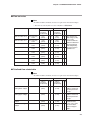
■ Device related data
Note
• For RD and WD commands, the data is required four hexadecimal digits.
Item
Data range
RAM
EEPROM
Remarks
Address
R W
Address
R W
Decimal
Decimal
(Hexadecimal)
(Hexadecimal)
Gas type
0: User setting
1: Nitrogen/Air
2: Oxygen
3: Argon
4: Carbon dioxide
5: Natural gas 13A
1001
(03E9)
❍ ✕
4001
(0FA1)
✕ ✕
Gas type change is
possible by function
setup (Address 5018)
The decimal point
is removed.
(Heating value: 46MJ/m3)
6: Propane
7: Methane
8: Butane
9: Hydrogen
10:Helium
11:Natural gas 13A
(Heating value: 45MJ/m3)
20
Full- scale flow
rate
Depend on flow rate
range
1002
(03EA)
❍ ✕
4002
(0FA2)
✕ ✕
Decimal point
position of
instantaneous
flow rate
0: No decimal point
1: XXXX.
2: XXX.X
3: XX.XX
4: X.XXX
1003
(03EB)
❍ ✕
4003
(0FA3)
✕ ✕
Decimal point
position of
integrated
flow rate
0: No decimal point
1: XXXXXXXX.
2: XXXXXXX.X
3: XXXXXX.XX
4: XXXXX.XXX
1004
(03EC)
❍ ✕
4004
(0FA4)
✕ ✕
Instantaneous
flow rate unit
0: mL/min
1: L/min
1005
(03ED)
❍ ✕
4005
(0FA5)
✕ ✕
Integrated
flow rate unit
0: L
1: m3
1006
(03EE)
❍ ✕
4006
(0FA6)
✕ ✕
Chapter 5. COMMUNICATION DATA TABLE
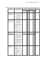
■ Operating status related data
Note
• For RD and WD commands, the data is required four hexadecimal digits.
• The flow rate unit "L/min" becomes "mL/min" in MQV9200.
Item
Data range
RAM
EEPROM
Remarks
Address
R W
Address
R W
Decimal
Decimal
(Hexadecimal)
(Hexadecimal)
Alarm status bit
Refer to *1
1201
(04B1)
❍ ✕
4201
(1069)
✕ ✕ For RS command,
status is shown in
decimal numbers
Event status bit
Refer to *2
1202
(04B2)
❍ ✕
4202
(106A)
✕ ✕ For RS command,
status is shown in
decimal numbers
Control status bit Refer to *3
1203
(04B3)
❍ ✕
4203
(106B)
✕ ✕ For RS command,
status is shown in
decimal numbers
Operation mode
1204
(04B4)
❍
4204
(106C)
❍ ❍ When the valve is in full
Instantaneous SP 0: SP-0
No. in use
1: SP-1
2: SP-2
3: SP-3
4: SP-4
5: SP-5
6: SP-6
7: SP-7
1205
(04B5)
❍ ❍
4205
(106D)
❍ ❍ When SP No. switching
Instantaneous
SP value in use
(0 to 100%FS)
L/min
1206
(04B6)
❍ ✕
4206
(106E)
✕ ✕
Instantaneous
PV value
(0 to 100%FS)
L/min
1207
(04B7)
❍ ✕
4207
(106F)
✕ ✕
Valve actuation
current
0.0 to 100.0%
1208
(04B8)
❍ ✕
4208
(1070)
✕ ✕
0: Valve full close
1: Valve control
2: Valve full open
❍
close or full open by
external inputs, write
operation is disabled.
is selected by external
inputs, write operation
is disabled.
The value larger than
the one selected with
SP No.(Address 5004)
of the function setup
can not be written.
The value in the data
range (L/min) is the
value removed
decimal point that
obtained by full scale
flow rate multiplied by
the percentage in
parentheses.
The decimal point is
removed .
21
Chapter 5. COMMUNICATION DATA TABLE
*1 : Alarm status bit configuration (Address 1201)
Bit No.
Description
0
Deviation lower limit alarm of instantaneous flow rate
(AL01)
1
Deviation upper limit alarm of instantaneous flow rate
(AL02)
2
Valve amperage lower limit alarm
(AL11)
3
Valve amperage upper limit alarm
(AL12)
4
Sensor error
5
Input / output adjustment data error
(AL91)
6
Sensor calibration data error
(AL92)
7
User setup data error
(AL93)
8
Valve overheat prevention limit operation
(AL71)
(common to AL81, AL82 and AL83)
9
Sensor error 1
(AL81)
10
Sensor error 2
(AL82)
11
Sensor error 3
(AL83)
*2 : Event status bit configuration (Address 1202)
Bit No.
0: OFF 1: ON
Description
0
Event output 1 status
1
Event output 2 status
2
Undefined (0 fixed)
3
External contact 1 input status
4
External contact 2 input status
5
External contact 3 input status
6
External 3-stage switching input status 1 (0V input)
7
External 3-stage switching input status 2 (5V input)
*3 : Alarm status bit configuration (Address 1203)
Bit No.
22
0: Normal 1: Error
0: OFF 1: ON
Description
0
OK lamp (PV control status)
0: Light-out 1: Lighting (Instantaneous PV OK)
1
Slow start operation
0: Normal operation 1: Slow start operation
2
Digital setting / Analog setting
0: Digital setting 1: Analog setting
3
Totalizing count status
0: Totalized flow PV < Totalized flow event SP
1: Totalized flow PV ≥ Totalized flow event SP
4
SP ramp control function
0: Function disabled 1: SP ramp control enabled
5
Undefined (0 fixed)
6
Undefined (0 fixed)
7
Undefined (0 fixed)
Chapter 5. COMMUNICATION DATA TABLE
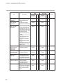
■ Flow set value
Note
• For RD and WD commands, the data is required four hexadecimal digits.
• The flow rate unit "L/min" becomes "mL/min" in MQV9200.
Item
Data range
RAM
EEPROM
Remarks
Address
R W
Address
R W
Decimal
Decimal
(Hexadecimal)
(Hexadecimal)
Flow set value SP-0
(0 to 100%FS)
L/min
1401
(0579)
❍ ❍
4401
(1131)
❍ ❍ The value in the
Flow set value SP-1
(0 to 100%FS)
L/min
1402
(057A)
❍ ❍
4402
(1132)
❍ ❍ is the value
Flow set value SP-2
(0 to 100%FS)
L/min
1403
(057B)
❍ ❍
4403
(1133)
Flow set value SP-3
(0 to 100%FS)
L/min
1404
(057C)
❍ ❍
4404
(1134)
Flow set value SP-4
(0 to 100%FS)
L/min
1405
(057D)
❍ ❍
4405
(1135)
❍ ❍
Flow set value SP-5
(0 to 100%FS)
L/min
1406
(057E)
❍ ❍
4406
(1136)
❍ ❍
Flow set value SP-6
(0 to 100%FS)
L/min
1407
(057F)
❍ ❍
4407
(1137)
❍ ❍
Flow set value SP-7
(0 to 100%FS)
L/min
1408
(0580)
❍ ❍
4408
(1138)
❍ ❍
data range (L/min)
removed decimal
point that obtained
❍ ❍ by full scale flow
rate multiplied by
❍ ❍ the percentage in
parentheses.
■ Totalized flow related data
Note
• For RD and WD commands, the data is required four hexadecimal digits.
Item
Data range
RAM
EEPROM
Remarks
Address
R W
Address
R W
Decimal
Decimal
(Hexadecimal)
(Hexadecimal)
Totalized flow event
setting lower 4 digits
0 to 9999
Totalized flow event
setting upper 4 digits
0 to 9999
Totalized flow lower
4 digits
0 to 9999
Totalized flow upper
4 digits
0 to 9999
1601
(0641)
❍ ❍
1602
(0642)
❍ ❍
1603
(0643)
❍ ❍
1604
(0644)
❍ ❍
4601
(11F9)
❍ ❍ Same as RAM
4602
(11FA)
❍ ❍ Same as RAM
4603
(11FB)
❍ ❍ When resetting the
4604
(11FC)
address 2218 and
5218 in parameter
set up.
address 2219 and
5219 in parameter
set up.
totalized value,
❍ ❍ make sure to write
“0” for the both
lower and upper
digits.
23
Chapter 5. COMMUNICATION DATA TABLE
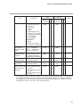
■ Function setup related data
Note
• For RD and WD commands, the data is required four hexadecimal digits.
Item
24
Data range
RAM
EEPROM
Address
R W
Address
R W
Decimal
Decimal
(Hexadecimal)
(Hexadecimal)
2001
❍ ❍
5001
❍ ❍
(07D1)
(1389)
Key lock Run
0: Key lock disabled
1: Settings other than
instantaneous SP and
integrated SP are keylocked
2: All settings key-locked
RUN key operation
selection and
operation mode
selection when
power turned ON
0: RUN key disabled
(Operation starts in the
control mode when the
power is turned ON)
1: RUN key enabled (1)
(Operation is started up
in the operating mode
used before power shutdown when the power
is turned ON)
2: RUN key enabled (2)
(Operation is started up
in the fully closed mode
when the power is turned ON)
2002
(07D2)
❍ ❍
5002
(138A)
❍ ❍
Flow rate setup
method (SP setup
method selection)
0: Digital setup (set by key
operation or
communications)
1: Analog setup (set by
external analog input
voltage)
2003
(07D3)
❍ ❍
5003
(138B)
❍ ❍
Number of flow set
value selection
(number of SPs
selection)
0: Number of SPs = 1
(SP-0 only)
1: Number of SPs = 2
(SP-0, SP-1)
2: Number of SPs = 3
(SP-0 to SP-2)
3: Number of SPs = 4
(SP-0 to SP-3)
4: Number of SPs = 5
(SP-0 to SP-4)
5: Number of SPs = 6
(SP-0 to SP-5)
6: Number of SPs = 7
(SP-0 to SP-6)
7: Number of SPs = 8
(SP-0 to SP-7)
2004
(07D4)
❍ ❍
5004
(138C)
❍ ❍
2005
(07D5)
❍ ❍
5005
(138D)
❍ ❍
Input range selection (1)Analog output selection
of analog setup
is set at voltage output
(analog SP input
(C-06 = 0, 1, 4, or 5).
range selection)
0: 0 to 5V internal
reference input
1: 0 to 5V external
reference input
2: 1 to 5V external
reference input
Remarks
Chapter 5. COMMUNICATION DATA TABLE
RAM
EEPROM
Address
R W
Address
R W
Decimal
Decimal
(Hexadecimal)
(Hexadecimal
Input range selection (2)Analog output selection
2005
❍ ❍
5005
❍ ❍
of analog setup
is set at current output
(07D5)
(138D)
(analog SP input
(C-06 = 2, 3, 6, or 7)
range selection)
0 : 0 to 20mA external
reference input
1 : 0 to 20mA external
reference input
2 : 4 to 20mA external
reference input
Item
Data range
Analog output type 0: 0 to 5V instantaneous
and range selection
flow rate output
(analog PV output 1: 1 to 5V instantaneous
range selection)
flow rate output
2: 0 to 20mA instantaneous
flow rate output
3: 4 to 20mA instantaneous
flow rate output
4: 0 to 5V setting flow rate
output
5: 1 to 5V setting flow rate
output
6: 0 to 20mA setting flow
rate output
7: 4 to 20mA setting flow
rate output
2006
(07D6)
❍ ❍
5006
(138E)
❍ ❍
Event 1 output type 0: Not used (OFF fixed)
assignment
1: ON when the totalized
2007
(07D7)
❍ ❍
5007
(138F)
❍ ❍
Event 2 output type
assignment
2:
3:
4:
5:
6:
flow event occurs
Totalized pulse output
ON when the flow rate is OK
ON in control mode
ON in fully open mode
ON in control or fully
open mode
7: ON in fully closed mode
8: PV upper limit event
9: PV lower limit event 1
10:PV lower limit event 2
-1 to -10: Inverse output of
above 1 to 10
(Normal operation: ON,
Event occurrence: OFF)
2008
(07D8)
❍ ❍
5008
(1390)
❍ ❍
External 3-stage
switching function
assignment
0: Not used
1: Switching of operating
mode 1
2: Switching SP No.
3: Switching of totalizing
operation
4: Switching of analog I/O
voltage range
(simultaneous external
switching of C-05 and
C-06)
5: Switching of operating
mode 2
2009
(07D9)
❍ ❍
5009
(1391)
❍ ❍
Remarks
25
Chapter 5. COMMUNICATION DATA TABLE
Item
External contact
input 1 function
assignment
External contact
input 2 function
assignment
External contact
input 3 function
assignment
26
Data range
0: Not used
1: Reset totalized flow count
2: Stop totalizing flow
count
3: Switching of SP No.
4: Switching of instantaneous
flow rate setup method
5: Valve forced fully closed
6: Valve forced fully open
7: Switching of slow start
operation or switching of
instantaneous SP ramp
control operation
8: Switching of operating
mode
(control by contact ON,
forced fully closed by
contact OFF)
9: Flow rate zero adjustment
10:Switching of gas type
setup
11:Switching of flow rate range
12:Switching of SP ramp
13:Alarm reset
RAM
EEPROM
Address
R W
Address
R W
Decimal
Decimal
(Hexadecimal)
(Hexadecimal)
2010
❍ ❍
5010
❍ ❍
(07DA)
(1392)
2011
(07DB)
❍ ❍
5011
(1393)
❍ ❍
2012
(07DC)
❍ ❍
5012
(1394)
❍ ❍
Automatic valve
shut-off when the
totalized flow
event occurs
0: Function disabled
1: Function enabled
2013
(07DD)
❍ ❍
5013
(1395)
❍ ❍
On/off of totalized
flow reset function
at start of control
0: Function disabled
1: Function enabled
2014
(07DE)
❍ ❍
5014
(1396)
❍ ❍
Flow rate alarm
setup type
0:
1:
2:
3:
2015
(07DF)
❍ ❍
5015
(1397)
❍ ❍
Operation selection 0: Control continued
at alarm occurrence
(alarm ignored)
1: Forced fully closed
2: Forced fully open
2016
(07E0)
❍ ❍
5016
(1398)
❍ ❍
Slow start setup
2017
(07E1)
❍ ❍
5017
(1399)
❍ ❍
Function disabled
Only upper limit alarm
Only lower limit alarm
Upper/lower limit alarm
0: Slow start disabled
1 to 8: Slow start enabled
(equivalent to approx. 1
to 6 seconds settling
time)
Remarks
Chapter 5. COMMUNICATION DATA TABLE
Item
Data range
Gas type selection 1 0: Conversion factor for
each gas type set by
the user
1: Air, nitrogen
2: Oxygen
3: Argon
4: Carbon dioxide (CO2)
5: Natural gas 13A (LNG)
(Heating value: 46MJ/m3)
6: 100% propane
7: 100% methane
8: 100% butane
9:Hydrogen
10:Helium
11: Natural gas 13A (LNG)
(Heating value: 45MJ/m3)
RAM
EEPROM
Address
R W
Address
R W
Decimal
Decimal
(Hexadecimal)
(Hexadecimal)
2018
❍ ❍
5018
❍ ❍
(07E2)
(139A)
Flow rate display
unit selection
(reference conditions)
0: 20˚C, 1 atmosphere
1: 0˚C, 1 atmosphere
2: 25˚C, 1 atmosphere
3: 35˚C, 1 atmosphere
2019
(07E3)
❍ ❍
5019
(139B)
❍ ❍
Valve amperage
alarm setup type
selection
0: Function disabled
1: Only upper limit alarm
2: Only lower limit alarm
3: Upper/lower limit alarms
2020
(07E4)
❍ ❍
5020
(139C)
❍ ❍
Direct setup
function ON/OFF
0: Function disabled
1: Function enabled
2021
(07E5)
❍ ❍
5021
(139D)
❍ ❍
Control dead
zone setting
0: Function disabled
1: Function enabled
2022
(07E6)
❍ ❍
5022
(139E)
❍ ❍
2023
(07E7)
❍ ❍
5023
(139F)
❍ ❍
PV filter
0: Without filter
(process for filtering 1: Two samplings moving
of instantaneous
average
flow rate)
2: Four samplings moving
average
3: Eight samplings moving
average
Remarks
*1
*1: The oxygen can not be set for other controllers except those shipped only for the oxygen gas application.
The hydrogen and helium gases can not be set for other controllers not subject to hydrogen and helium
gas applications. Also the controllers subjected to the hydrogen and helium gases can not be set for the
standard gases of Items 1 to 8 and 11 given in the data range.
27
Chapter 5. COMMUNICATION DATA TABLE
Item
Data range
RAM
EEPROM
Address
R W
Address
R W
Decimal
Decimal
(Hexadecimal)
(Hexadecimal)
0: Standard range
10 to 99: 10% to 99% of
standard range. (When
calculating the range
reduction, the least significant digit is truncated.)
-10 to -99: 10% to 99% of
standard range. (When
calculating the range
reduction, the least significant digit is not
truncated.)
2024
(07E8)
2025
(07E9)
❍ ❍
Gas type selection 2 0: Conversion factor for
each gas type set by
the user
1: Air, nitrogen
2: Oxygen
3: Argon
4: Carbon dioxide (CO2)
5: Natural gas 13A (LNG)
(Heating value: 46MJ/m3)
6: 100% propane
7: 100% methane
8: 100% butane
9: Hydrogen
10: Helium
11: Natural gas 13A (LNG)
(Heating value: 45MJ/m3)
2026
(07EA)
SP ramp control
function
Flow rate range
setup 1
Flow rate range
setup 2
Analog scaling
function
Forced PV
(instantaneous
flow rate) zero
function
0: Function disabled
1: SP ramp control 1.
(In SP ramp-up: ramp 1,
in SP ramp-down: ramp 2)
2: SP ramp control 2.
(In external contact OFF:
ramp 1, in external
contact ON: ramp 2)
0: Function disabled
1: Function enabled
0: Function disabled
1: Function enabled
5024
(13A0)
5025
(13A1)
❍ ❍
❍ ❍
5026
(13A2)
❍ ❍
2027
(07EB)
❍ ❍
5027
(13A3)
❍ ❍
2028
(07EC)
2029
(07ED)
❍ ❍
5028
(13A4)
5029
(13A5)
❍ ❍
❍ ❍
❍ ❍
Remarks
❍ ❍
*1
❍ ❍
*1: The oxygen can not be set for other controllers except those shipped only for the oxygen gas application.
The hydrogen and helium gases can not be set for other controllers not subject to hydrogen and helium
gas applications. Also the controllers subjected to the hydrogen and helium gases can not be set for the
standard gases of Items 1 to 8 and 11 given in the data range.
28
Chapter 5. COMMUNICATION DATA TABLE
RAM
EEPROM
Remarks
Address
R W
Address
R W
Decimal
Decimal
(Hexadecimal)
(Hexadecimal)
Station address
0: Communications
2030
❍ ✕
5030
❍ ✕ Though a
normal
setting
function disabled
(07EE)
(13A6)
termination
1 to 127: Station address
code is
Transmission
0: 38400bps
2031
❍ ✕
5031
❍ ✕ returned
speed selection
1: 19200bps
(07EF)
(13A7)
after
2: 9600bps
sending the
write
3: 4800bps
instruction
4: 2400bps
message,
Data format selection 0: 8 data bits, even parity,
2032
❍ ✕
5032
❍ ✕ the data
1 stop bit
(07F0)
(13A8)
cannot be
written.
1: 8 data bits, no parity,
2 stop bits
Item
Data range
SP limit function
0: SP limit function
disabled
1: Only upper limit enabled
2: Only lower limit enabled
3: Upper and lower limits
enabled
Operational
0: Low differential pressure
differential pressure
(50 ± 50kPa)
setting (control
1: Standard differential
optimization)
pressure (200 ± 100kPa)
2: High differential pressure
(300+0, -100kPa)
Flow rate display
0: Flow rate is displayed in
unit change functhe standard flow rate
tion
unit.
1: Flow rate is displayed in
[L/min] fixed.
-1:Flow rate is displayed in
[mL/min] fixed.
PV (instantaneous 0: Decimal point position is
flow rate) display
not changed
decimal point posi- 1: Decimal point position is
tion change function
shifted one digit left
-1:Decimal point position is
shifted one digit right
2035
(07F3)
❍ ❍
5035
(13AB)
❍ ❍
2036
(07F4)
❍ ❍
5036
(13AC)
❍ ❍ This func-
2037
(07F5)
❍ ❍
5037
(13AD)
❍ ❍ This func-
2038
(07F6)
❍ ❍
5038
(13AE)
❍ ❍
tion is invalid for the
MQV0050
(J, K).
tion is valid
only for the
MQV9200/
9500/0002/
0005.
29
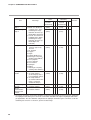
Chapter 5. COMMUNICATION DATA TABLE
■ Parameter setup related data
Note
• For RD and WD commands, the data is required four hexadecimal digits.
• When the function setup is not valid, parameter setup is invalid.
• The decimal point of all data is removed.
Item
Instantaneous flow rate
O.K judgment range
(0.5 to 100%FS)
2202
(089A)
❍ ❍
5202
(1452)
❍ ❍
Instantaneous flow rate
(0.5 to 100%FS)
deviation upper limit alarm
2203
(089B)
❍ ❍
5203
(1453)
❍ ❍
Instantaneous flow rate
(0.5 to 100%FS)
deviation upper limit alarm
hysteresis
2204
(089C)
❍ ❍
5204
(1454)
❍ ❍
Instantaneous flow rate
(0.5 to 100%FS)
deviation lower limit alarm
2205
(089D)
❍ ❍
5205
(1455)
❍ ❍
Instantaneous flow rate
(0.5 to 100%FS)
deviation lower limit alarm
hysteresis
2206
(089E)
❍ ❍
5206
(1456)
❍ ❍
Instantaneous flow rate
deviation alarm judgment
delay time
0.5 to 999.9s
2207
(089F)
❍ ❍
5207
(1457)
❍ ❍
Event output 1 delay
0.0 to 999.9s
2208
(08A0)
❍ ❍
5208
(1458)
❍ ❍
Event output 2 delay
0.0 to 999.9s
2209
(08A1)
❍ ❍
5209
(1459)
❍ ❍
User setup conversion
factor
0.04 to 9.999
2210
(08A2)
❍ ❍
5210
(145A)
❍ ❍
Valve amperage upper
limit alarm
0.1 to 100.0%
2211
(08A3)
❍ ❍
5211
(145B)
❍ ❍
Valve amperage lower
limit alarm
0.0 to 99.9%
2212
(08A4)
❍ ❍
5212
(145C)
❍ ❍
Event output 1 upper/
lower limit flow rate setup
(0 to 100%FS)
2213
(08A5)
❍ ❍
5213
(145D)
❍ ❍
Event output 2 upper/
lower limit flow rate setup
(0 to 100%FS)
2214
(08A6)
❍ ❍
5214
(145E)
❍ ❍
MQV9200/9500:
0.0 to 999.9
MQV0002/0005:
0.000 to 9.999
MQV0010/0020/
0050:
0.00 to 99.99
MQV0200/0500:
0.0 to 999.9
MQV1000:
0 to 9999
2215
(08A7)
2216
(08A8)
❍ ❍
5215
(145F)
5216
(1460)
❍ ❍
Instantaneous flow rate
O.K judgment hysteresis
SP ramp control ramp 1
SP ramp control ramp 2
30
RAM
EEPROM
Remarks
Address
R W
Address
R W
Decimal
Decimal
(Hexadecimal)
(Hexadecimal)
(0.5 to 100%FS)
2201
❍ ❍
5201
❍ ❍ Unit: L/min
(standard)
(0899)
(1451)
Data range
❍ ❍
❍ ❍
(mL/min
(standard) for
the MQV9200.)
Delay does
not apply to
totalizer pulse
output.
Unit: L/min
(standard)
(mL/min
(standard) for
the MQV9200.)
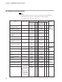
Chapter 5. COMMUNICATION DATA TABLE
Item
Data range
RAM
Address
R
Decimal
(Hexadecimal)
W
EEPROM
Address
R
Decimal
(Hexadecimal)
W
Remarks
(10 to 100% FS)
2217
(08A9)
❍ ❍
5217
(1461)
❍ ❍
Unit: L/min
(standard)
(mL/min
(standard) for
the MQV9200.)
Cumulative flow event
setting (last 4 digits)
0 to 9999
2218
(08AA)
❍ ❍
5218
(1462)
❍ ❍
Same as
address 1601
and 4601.
Cumulative flow event
setting (first 4 digits)
0 to 9999
2219
(08AB)
❍ ❍
5219
(1463)
❍ ❍
Same as
address 1602
and 4602.
PV forced zero function
delay
0.0 to 999.9s
2220
(08AC)
❍ ❍
5220
(1464)
❍ ❍
SP upper limit flow rate
(0 to 100% FS)
2221
(08AD)
❍ ❍
5221
(1465)
❍ ❍
SP lower limit flow rate
(0 to 100% FS)
2222
(08AE)
❍ ❍
5222
(1466)
❍ ❍
Analog scaling
Unit: L/min
(standard)
(mL/min
(standard) for
the MQV9200.)
31
Chapter 6. COMMUNICATION PROGRAM FOR MASTER STATION
6 - 1
Precautions for Programming
●
The maximum response moniter time of the instrument is 2 seconds. So, set the response time-out to 2
seconds.
●
If no response is obtained within 2 seconds, retransmit the same message.
●
The above retransmission is required since a message may not be properly transmitted due to noise or the
like during communications.
Note
When “X” is used as the device ID code in the instruction message, the device
ID code of the response message also becomes “X”. Likewise, the code in the
response message becomes “x” when “x” is used as the device code in the
instruction message.
Use the “X” and “x” device ID codes alternately during message retransmission from the master station, to make it easier to identify whether the received
response message is the current one or the preceding one.
32
Chapter 6. COMMUNICATION PROGRAM FOR MASTER STATION
6 - 2
Examples of Communication Program
The program in this section is written in Borland's C++Builder5.0 or Borland C++Compiler5.5 for
Windows95/98/NT/2000.
This program is given here as a reference when the user makes a program, and does not assure all the operations.
You can download Borland C++Compiler5.5 from Borland Home Page.
■ Before executing the program
Make sure to check the settings for communications type, station address, transmission speed and data format of the instrument.
■ Executing the program
This program is used for reading and writing data. When the program is executed,
the application layers of the instruction message and response message
communicated are indicated.
command:RS,1001W,2
result:00,0,0
command:WS,1204W,2
result:00
Sample indication of execution results
● Processing of the sample program
• Communication settings
Call open() and initialize the RS-232C serial port.
• Command execution
Set a desired character string in 'command' and call AppCPL().
33
Chapter 6. COMMUNICATION PROGRAM FOR MASTER STATION
■ Data read/write sample program
Handling Precautions
Yamatake won't be absolutely responsible for any trouble caused by applying this program sample.
34
Chapter 6. COMMUNICATION PROGRAM FOR MASTER STATION
35
Chapter 6. COMMUNICATION PROGRAM FOR MASTER STATION
36
Chapter 6. COMMUNICATION PROGRAM FOR MASTER STATION
37
Chapter 6. COMMUNICATION PROGRAM FOR MASTER STATION
38
Chapter 7.
TROUBLESHOOTING
■ Check items in case communication is disabled
(1) Check the power supply.
(2) Check the wiring.
(3) Check if the communication conditions for the CMQ-V Series meet those for
the host computer.
If any one of the following setting items is different between both stations,
communication is disabled:
The underlined items mean that they can be set on the CMQ-V Series side.
Transmission seed : 38400, 19200, 9600, 4800, 2400bps
Data length
: 7, 8 bits
Parity
: No parity, odd parity, even parity
Stop bit
: 1 stop bit, 2 stop bits
(4) Check if the destination address of the command frame transmitted from the
host computer meets the address set to the CMQ-V Series.
The address of the CMQ-V Series set to “0” for factory setting.
Even when the destination address of the command frame is set to 00 (30H,
30H), the CMQ-V Series does not respond to such a message.
(5) Use the upper-case character codes for all the character codes other than the
device code (“X” or “x” in this controller).
(6) Are those multi-dropped controllers belong operated themselves with different
device address setups?
(7) Is the communication timing conformed with the Chapter 4-5 Timing
Specifications (page 16)?
39
Chapter 8.
SPECIFICATIONS
■ RS-485 specifications
Item
40
Remarks
Transmission mode
Balanced
Transmission line
3-wire system
Transmission speed (bps)
2400, 4800, 9600, 19200, 38400
Transmission distance
500m max.
(300m when connected with the MA500DIM and CMC410.)
Communications flow
Half duplex
Synchronization
Start-stop synchronization
Data format
8 data bits, 1 stop bit, even parity
8 data bits, 2 stop bits, no parity
Error detection
Parity check, checksum
Station address
0 to 127
(Communication function is inhibited when set to “0”.)
Network type
1: N
(31 units max.)
The rest of items
Conforms to RS-485 interface specifications.
APPENDIX
■ Code table
Upper
0
1
2
3
4
5
6
7
0
Space
0
@
P
`
p
1
!
1
A
Q
a
q
Lower
2
STX
"
2
B
R
b
r
3
ETX
#
3
C
S
c
s
4
$
4
D
T
d
t
5
%
5
E
U
e
u
6
&
6
F
V
f
v
7
'
7
G
W
g
w
8
(
8
H
X
h
x
9
)
9
I
Y
i
y
*
:
J
Z
j
z
B
+
;
K
[
k
{
C
,
<
L
\
l
|
-
=
M
]
m
}
E
.
>
N
^
n
~
F
/
?
O
_
o
^
A
D
LF
CR
The shaded parts of the table above (
system.
) are not used for this communication
41
APPENDIX
■ Connection with CMC10L
The CMC10L001A000 is available as an RS-232C/RS-485 (3-wire system) converter from Yamatake's. The following diagram shows an example of wiring using
a straight cable for a host computer in the terminal mode:
CMQ-V Series
(slave station)
7
8
Terminating
resistor
Terminal
block
*
9
DA
DB
SG
CMQ-V Series
(slave station)
7
8
DA
DB
Shielded cable
*
9
SG
FG
RD
SD
DA
MOD.
2
2
3
3
DB
TER.
MOD.
TER.
CMQ-V Series
(slave station)
SG
7
RS
CS
DR
SG
ER
CD
7
7
8
8
6
6
5
5
4
4
1
1
8
Shielded cable
*
Host computer
9
DA
DB
SG
FG
CMQ-V Series
(slave station)
Terminating
resistor
CMC10L
7
Terminal
block
8
*
9
DA
DB
SG
* : The pin No. 6 can be used as SG.
• Connect terminating resistors of 150Ω±5%, 1/2W min. at each end of the transmission line.
• Terminal block is required for the CMQ-V series because of the connector type
connection.
• The cable to the terminal block from the CMQ-V series must be as short as possible.
• The FG grounding must not be made at the both shielded wire ends but only at
one location.
Handling Precautions
42
Be sure to connect SG terminals each other. Failure to do so might cause
unstable communications.
APPENDIX
Connect the master station SD to the slave station RD, and the master station RD
to the slave station SD.
To execute this connection, set the MODE switch provided in the CMC10L as
shown in the following table in accordance with the host computer side RS-232C
connector pin arrangement (modem/terminal) and the type of cable (cross/straight)
used:
RS-232C
Cable type
MODE switch
TERMINAL
Straight
MODEM
TERMINAL
Cross
TERMINAL
MODEM
Straight
TERMINAL
MODEM
Cross
MODEM
● RS-232C cable
Straight: An RS-232C cable with a D-Sub (9-pin) connector at each end where
pins with the same number are mutually connected (for example, pin 2
to pin 2, and pin 3 to 3)
CD
RD
SD
ER
SG
DR
RS
CS
Cross:
1
2
3
4
5
6
7
8
1
2
3
4
5
6
7
8
CD
RD
SD
ER
SG
DR
RS
CS
An RS-232C cable with a D-Sub (9-pin) connector at each end where
different number pins are connected (for example, pin 2 to pin 3, and
pin 3 to pin 2)
RD
SD
RS
CS
DR
ER
CD
SG
2
3
7
8
6
4
1
5
2
3
7
8
6
4
1
5
RD
SD
RS
CS
DR
ER
CD
SG
D-Sub (25-pin) – D-Sub (9-pin) conversion cable:
An RS-232C cable for conversion between D-Sub (25-pin) and D-Sub
(9-pin)
FG
SD
RD
RS
CS
DR
ER
CD
SG
1
2
3
4
5
6
20
8
7
3
2
7
8
6
4
1
5
SD
RD
RS
CS
DR
ER
CD
SG
43
Revision History
Printed
date
Manual Number
Edition
Jan. 2007 CP-SP-1197E 1st Edition
Revised pages
Description
Specifications are subject to change without notice.
Advanced Automation Company
1-12-2 Kawana, Fujisawa
Kanagawa 251-8522 Japan
URL: http://www.azbil.com
Printed on recycled paper.
(07)
Printed in Japan.
1st Edition: Issued in Jan. 2007 (U)