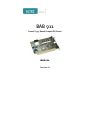
1
BAB 911
PowerPC 755 Based CompactPCI Board
manual
Revision 1B
Revision
Revision Changes
Date / Name
0A
First Edition
17.01.02 abr
1A
First Edition, valid for Hardware revision 1B
05.02.02 GM
1B
Disclaimer new
08.11.06 hh
DISCLAIMER
Copyright
© 2006 ELTEC Elektronik AG. The information, data, and figures in this
document including respective references have been verified and
found to be legitimate. In particular in the event of error they may,
therefore, be changed at any time without prior notice. The complete
risk inherent in the utilization of this document or in the results of its
utilization shall be with the user; to this end, ELTEC Elektronik AG shall
not accept any liability. Regardless of the applicability of respective
copyrights, no portion of this document shall be copied, forwarded or
stored in a data reception system or entered into such systems without
the express prior written consent of ELTEC Elektronik AG, regardless of
how such acts are performed and what system is used (electronic,
mechanic, photocopying, recording, etc.). All product and company
names are registered trademarks of the respective companies.
Our General Business, Delivery, Offer, and Payment Terms and
Conditions shall otherwise apply.
Federal communications commission statement
Þ This device complies with FCC Rules Part 15. Operation is subject
to the following two conditions:
Þ This device may not cause harmful interference, and
Þ This device must accept any interference received including
interference that may cause undesired operation.
Þ This equipment has been tested and found to comply with the
limits for a Class B digital device, pursuant to Part 15 of the FCC
Rules. These limits are designed to provide reasonable protection
against harmful interference in a residential installation. This
equipment generates, uses and can radiate radio frequency
energy and, if not installed and used in accordance with
Þ
Þ
Þ
Þ
Þ
manufacturer’s instructions, may cause harmful interference to
radio communications. However, there is no guarantee that
interference will not occur in a particular installation. If this
equipment does cause harmful interference to radio or television
reception, which can be determined by turning the equipment off
and on, the user is encouraged to try correct the interference by
one or more of the following measures:
Reorient or relocate the receiving antenna.
Increase the separation between the equipment and receiver.
Connect the equipment to an outlet on a circuit different from
that to which the receiver is connected.
Consult the dealer or an experienced radio/TV technician for help.
The us of shielded cables for connection of the monitor to the
graphics card is required to assure compliance with FCC
regulations. Changes or modifications to this unit not expressly
approved by the party responsible for compliance could void the
user’s authority to operate this equipment.
Canadian department of communications statement
Þ This digital apparatus does not exceed the Class B limits for radio
noise emissions from digital apparatus set out in the Radio
Interference Regulations of the Canadian Department of
Communications.
Þ This class B digital apparatus complies with Canadian ICES-003
SAFETY INFORMATION
Electrical safety
Þ To prevent electrical shock hazard, disconnect the power cable
from the electrical outlet before reloading the system.
Þ When adding or removing devices to or from the system, ensure
that the power cables for the devices are unplugged before the
signal cables are connected. If possible, disconnect all power
cables from the existing system before you add device.
Þ Before connecting or removing signals cables from motherboard,
ensure that all power cables are unplugged.
Þ Make sure that your power supply is set to the correct voltage in
your area. If you are not sure about the voltage of the electrical
outlet you are using, contact your local power company.
Þ If the power supply is broken, do not try to fix it by yourself.
Contact a qualified service technician or your retailer.
Operation safety
Þ Before installing the motherboard and adding devices on it,
carefully read the manuals that came with the package.
Þ Before using the product, make sure all cables are correctly
connected and the power cables are not damaged. If you detect
any damage, contact your dealer immediately.
Þ To avoid short circuits, keep paper clips, screws, and staples away
from connectors, slots sockets and circuitry.
Þ Avoid dust, humidity, and temperature extremes. Do not place the
product in any area where it may become wet.
Þ Place the product on a stable surface.
Þ If you encounter technical problems with the product, contact a
qualified service technician or your retailer.
EMC Rules
This unit has to be installed in a shielded housing. If not installed in a
properly shielded enclosure, and used in accordance with the
instruction manual, this product may cause radio interference in which
case the user may be required to take adequate measures at his or her
own expense.
IMPROTANT INFORMATION
This product is not an end user product. It was developed and
manufactured for further processing by trained personnel.
RECYCLING
Please recycle packaging environmentally friendly:
Packaging materials are recyclable. Please do not dispose
packaging into domestic waste but recycle it.
Please recycle old or redundant devices environmentally
friendly:
Old devices contain valuable recyclable materials that should
be reutilized. Therefore please dispose old devices at collection points
which are suitable.
User's Manual
Table of Contents
Table of Contents
1 Specification .................................................................... 1—1
1.1 Main Features................................................................. 1—1
1.2 Specification Details ....................................................... 1—2
1.2.1 CPU Kernel.................................................................. 1—2
1.2.2 Memory Configuration ................................................. 1—2
1.2.3 Chip set ....................................................................... 1—3
1.2.4 Boot PROM ................................................................. 1—3
1.2.5 Ethernet Interface ........................................................ 1—3
1.2.6 Serial I/O...................................................................... 1—3
1.2.7 PISA Interface ............................................................. 1—4
1.2.8 Timer............................................................................ 1—4
1.2.9 Non-volatile Memory.................................................... 1—4
1.2.10 Operating systems..................................................... 1—5
1.2.11 On-board I/O.............................................................. 1—5
1.2.12 Miscellaneous............................................................ 1—5
1.2.13 Related Documents ................................................... 1—5
2 Installation........................................................................ 2—1
2.1 BAB 911 I/O.................................................................... 2—1
BAB 911
I
Table of Contents
User's Manual
2.1.1 What‘s needed for Installation ..................................... 2—2
2.1.2 SODIMM Installation.................................................... 2—2
2.1.3 Status LEDs................................................................. 2—3
2.1.4 Ethernet Status LEDs .................................................. 2—3
3 Connector Assignments ................................................. 3—1
3.1 Front Panel Connectors.................................................. 3—1
3.1.1 Ethernet Connector ..................................................... 3—1
3.1.2 Serial Ports 1 and 2 Connectors ................................. 3—1
3.1.3 PISA Connector........................................................... 3—2
4 Board Parameters............................................................ 4—1
4.1 Host Bus ......................................................................... 4—1
4.2 PCI Local Bus ................................................................. 4—1
4.3 Network .......................................................................... 4—1
4.4 Serial I/O......................................................................... 4—2
4.5 MTBF Values .................................................................. 4—2
4.6 ESD Values .................................................................... 4—2
4.7 Environmental Conditions .............................................. 4—2
4.8 Maximum Operating Humidity: ....................................... 4—3
4.9 Power Requirements ...................................................... 4—3
II
BAB 911
User's Manual
Table of Contents
5 Jumpers............................................................................ 5—1
5.1 On-board Jumpers.......................................................... 5—1
5.1.1 User-settable Jumpers ................................................ 5—2
6 Appendix .......................................................................... 6—1
6.1 Description of On-board Devices ................................... 6—1
6.1.1 Memory Address Map ................................................. 6—2
6.1.2 Interrupt Controller....................................................... 6—3
6.1.3 Watchdog .................................................................... 6—4
6.1.4 Configuration Switch.................................................... 6—4
6.1.5 Status Display.............................................................. 6—5
6.1.6 Non Volatile RAM ........................................................ 6—5
6.1.7 Serial Controller........................................................... 6—6
6.1.8 Soft Reset.................................................................... 6—6
6.1.9 Turbo Mode ................................................................. 6—6
BAB 911
III
Table of Contents
User's Manual
List of Tables
Table 2—1: Ethernet Status LEDs ....................................... 2—4
Table 3—1: ETHERNET (8-pin Telephone Jack Connector)3—1
Table 3—2: COM1, COM2 (9-pin min-D Connector) ........... 3—1
Table 3—3: PISA Connector ................................................ 3—2
Table 5—1: Boot ROM Select (J601_1)............................... 5—2
Table 5—2: External ROM Select (J601_2) ......................... 5—2
Table 5—3: External ROM Chipselect (J601_3) .................. 5—2
Table 5—4: Revision-PROM Write-Protection (J201) .......... 5—2
Table 6—1: Memory Address Map....................................... 6—2
Table 6—2: Watchdog Address Assignment........................ 6—4
Table 6—3: Configuration Switch Address Assignment....... 6—4
Table 6—4: Status Display Address Assignment................. 6—5
Table 6—5: Non Volatile RAM Address Assignment ........... 6—5
IV
BAB 911
User's Manual
Table of Contents
List of Figures
Figure 1—1: Block Diagram ................................................. 1—6
Figure 2—1: Connection Diagram ........................................ 2—1
Figure 2—2: LEDs ................................................................ 2—3
Figure 2—3: Ethernet Status LEDs ...................................... 2—3
Figure 5—1: Parts Side Jumpers ......................................... 5—1
Figure 6—1: BAB 911 Interrupt Diagram ............................. 6—3
Figure 6—2: LEDs ................................................................ 6—5
BAB 911
V
Table of Contents
VI
BAB 911
User's Manual
Specification
Specification
User's Manual
1 Specification
1.1 Main Features
· PowerPC-based PCISA CPU board
· PCI master interface
· CPU PowerPC 750CX(e) 400 MHz
· 256 KB on-chip L2-cache
· Up to 256 MByte SDRAM on SODIMM
· 10 / 100 Mbit/s network interface (10BaseT / 100BaseTX)
· Two serial channels
· 2 KB nvSRAM for storing application- / process-data
· PCISA (PISA) format with PCI interface for up to 4 slots
· OS-9 BSP support
BAB 911
1—1
Specification
User's Manual
Specification
1.2 Specification Details
The BAB 911 is a PowerPC-based single board computer with a
PISA interface. The small format permits setting up small industrial
realtime systems.
The board is based on the Motorola MPC 107 chip, the reference for
PowerPC designs. Also, availability for longer periods than what is
common in the PC market is guaranteed.
1.2.1 CPU Kernel
An up-to-date PowerPC CPU is supported: PowerPC 750CXe,
compatible to the PowerPC 750 at 400 MHz. The CPU has FPU,
MMU, first level cache (32KB each for instruction and data) and a
L2 cache (256 KB unified) on the chip. It contains dual integer units,
that can operate in parallel for certain instructions; the floating point
unit is optimized for fast single precision multiply-add operations.
Performance is characterized by the SPECint numbers of 17.4 and
SPECfp 11.7.
1.2.2 Memory Configuration
The 64-bit wide memory allows configurations of up to 256 (512
when available) MByte with 100 MHz SDRAMs in a single
SODIMM module. The implementation in SODIMM has been
selected due to the smaller size and thus shorter signals, compared to
standard DIMM modules. Memory size is detected automatically.
The second-level cache, due to its location in the CPU itself, runs
with the full CPU clock.
1—2
BAB 911
Specification
1.2.3 Chip set
The chip set, a Motorola MPC 107, contains the SDRAM memory
controller, the interrupt controller, and the PCI host bridge for 32bit/33-MHz PCI. Additionally, it has logic to access an 8-bit wide
ROM, it has timers, a DMA controller, and it generates clocks.
1.2.4 Boot PROM
Boot code is stored in a Flash EPROM (size 512 KB) which enables
easy code updates. The current boot proms contains self test code,
PCI initialization routines, as well as OS boot code for OS-9 via
Ethernet (BootP).
1.2.5 Ethernet Interface
The network interface uses the network controller i82559ER for
10/100 Mbit/s transfers with 10BaseT (twisted pair) or 100Base TX
connectivity. Automatic speed detection is included. A Link LED
and an Activity LED allow an easy check whether the Ethernet
connection works.
1.2.6 Serial I/O
Two asynchronous 16550-compatible serial channels with up to 115
KBaud transfer rate and 16-byte FIFO with RS232 levels are
available.
BAB 911
1—3
Specification
User's Manual
Specification
User's Manual
Specification
1.2.7 PISA Interface
The PISA interface is implemented with system slot capabilities for
32-bit PCI systems. It features transfer rates of up to 128 MByte/s
between board-internal resources and PISA devices. The PISA
interface uses only the PCI bus signals.
The board must occupy the PCI system slot and it will set up all PCI
peripherals on the PCI back plane. The board can drive PCI buses
(passive back planes) with up to 4 peripheral slots, all of them can
obtain bus mastership (DMA).
1.2.8 Timer
The BAB 911 has four programmable timers, located in the MPC
107, for timing interrupts in the 1 µs to 1000 ms range. Three of
these timers are intended for use with user-written drivers, they are
not used by the operating system or the BSP, one may be used by the
OS.
The additional CPU-internal decrementer is used for generating the
OS ticker interrupt.
1.2.9 Non-volatile Memory
A non-volatile memory for storing system boot parameters (512 B) is
mounted on the board, and additionally 2 KB user memory that is
not used by ELTEC.
User memory is implemented in a non-volatile RAM using a
combination of SRAM and EEPROM. The EEPROM is
automatically programmed with SRAM data during power-down and
supplies data to the SRAM during power-up. Data transfer rate is 5
MByte/s. Only byte-access is allowed.
1—4
BAB 911
Specification
1.2.10 Operating systems
The software support for the BAB 911 includes the board support
package for OS-9 3.0.
1.2.11 On-board I/O
All on-board-I/O (2 * serial and 100BaseTx) is routed to the front
panel.
1.2.12 Miscellaneous
Due to the use of a PISA connector the number of external PCI slots
is limited to 4. If more than 4 external slots are needed, a back plane
with an integrated PCI-PCI bridge must be used.
1.2.13 Related Documents
IBM PowerPC 750CX/750CXe RISC Microprocessor User's
Manual. This is the CPU manufacturer's description of the PowerPC
itself and the assembly language command set.
Motorola MPC 107 PCI Bridge/Memory Controller User's Manual.
BAB 911
1—5
Specification
User's Manual
Specification
User's Manual
Specification
Figure 1—1: Block Diagram
2MB User-Flash
(optional)
PPC750CX(e)
(256 KB L2 Cache)
Processor Bus
100 MHz / 64 Bit
Flash-EPROM
(512 KB Boot)
nvSRAM
(2 KB User)
RevEPROM
I²C Bus
Peripheral Bus
8 Bit
MPC 107
Serial #1/2
SODIMM
(32..256 MB)
Memory Bus
100 MHz / 64 Bit
PCI Bus
33 MHz / 32 Bit
HEX-Switch,
LED-Display,
Watchdog
Ethernet
10/100 MBit
PCISA Interface
(PISA Connector)
PCI Bus
33 MHz / 32 Bit
PCI Slot #1
1—6
PCI Slot #2
BAB 911
PCI Slot #3
PCI Slot #4
User's Manual
Installation
2 Installation
Installation
2.1 BAB 911 I/O
Figure 2—1: Connection Diagram
Serial #2
Status LEDs
Ethernet
Serial #1
BAB 911
2—1
Installation
User's Manual
2.1.1 What‘s needed for Installation
Installation
The BAB 911 must be installed into a PISA backplane. A terminal
(or a PC with a terminal emulator program) connected to serial #1
and set to 9600 baud, 8 bit, no parity, is needed to check boot
messages and to change boot settings. If the operating system is
booted over Ethernet, a network connection is needed.
2.1.2 SODIMM Installation
The BAB 911 requires one 144-pin SODIMM SDRAM module, that
supports CAS-latency 2 at 100 MHz, to be fitted into the SODIMM
socket X701. These modules are currently available with a capacity
of up to 256 Mbyte. In the near future there may also be 512 Mbyte
modules that are supported by the BAB 911. The firmware reads the
type and size of the SODIMM from the SPD (Serial Presence
Detect) EEPROM installed on the memory module, and tests the
module. If the test fails or the firmware reports the wrong size the
module is not suitable for the BAB 911.
2—2
BAB 911
User's Manual
Installation
2.1.3 Status LEDs
Installation
There are four status LEDs on the front panel of the BAB 911. The
LEDs are controlled by software.
Figure 2—2: LEDs
3
2
1
0
2.1.4 Ethernet Status LEDs
At the ethernet connector there are two LEDs indicating link status
and network activity.
Figure 2—3: Ethernet Status LEDs
Activity
Ethernet
Link
BAB 911
2—3
Installation
User's Manual
Table 2—1: Ethernet Status LEDs
LED
Activity
Installation
Link
2—4
Color
Green
Yellow
off
Green
Yellow
Off
Description
Board power ok; network not initialized or no link pulses
Network activity
Link pulses detected; no network activity
100 Mbit/s link pulses detected
10 Mbit/s link pulses detected
No link pulses detected
BAB 911
User's Manual
Connector Assignments
3 Connector Assignments
Please check the connector assignments before using any interface.
3.1 Front Panel Connectors
3.1.1 Ethernet Connector
Pin
1
2
3
4
5
6
7
8
Signal
TXD+
TXDRXD+
nc
nc
RXDnc
nc
1
Connector
Assignments
Table 3—1: ETHERNET (8-pin Telephone Jack Connector)
8
Front View
3.1.2 Serial Ports 1 and 2 Connectors
Table 3—2: COM1, COM2 (9-pin min-D Connector)
Pin
1
2
3
4
5
6
7
8
9
Signal
DCD
RXD
TXD
DTR
GND
DSR
RTS
CTS
RI
Front View
Pin 1
BAB 911
3—1
Connector Assignments
User's Manual
3.1.3 PISA Connector
Table 3—3: PISA Connector
Pin
Connector
Assignments
1
2
3
4
5
6
7
8
9
10
11
12
13
14
15
16
17
18
19
20
21
22
23
24
25
26
27
28
29
30
31
32
33
34
35
36
37
38
39
40
41
42
43
44
3—2
ISA-Bus
top layer
bot layer
up row
up row
GND
VCC
-12V
+12V
GND
VCC
GND
PCIbus
top layer
bot layer
low row
low row
I2CLK
I2DAT
GND
GND
INTB#
INTA#
INTD#
INTC#
VCC
VCC
VCC
PCIRST#
GNT#0
REQ#0
GND
PCICLK1
GND
AD30
REQ#2
VI/O
PCICLK2
GND
GNT#1
GND
REQ#1
AD31
AD29
PCICLK3
GNT#2
AD28
AD26
AD24
AD22
AD20
AD18
PWRGDIN
PCICLK4
AD27
AD25
CBE#3
AD23
AD21
AD19
REQ#3
GND
AD16
FRAME#
CBE#2
TRDY#
STOP#
GNT#3
AD17
IRDY#
DEVSEL#
LOCK#
PERR#
GND
CBE#1
PAR
GND
SERR#
AD15
AD14
AD12
GND
GND
AD13
AD11
AD9
CBE#0
AD6
M66EN
AD10
AD8
AD7
AD5
AD3
BAB 911
User's Manual
VCC
AD4
AD2
AD1
AD0
VCC
VCC
GND
GND
VI/O
VCC
GND
GND
GND
Connector
Assignments
45
46
47
48
49
50
51
52
Connector Assignments
BAB 911
3—3
Connector Assignments
Connector
Assignments
3—4
BAB 911
User's Manual
User's Manual
Board Parameters
4 Board Parameters
4.1 Host Bus
100 MHz
4.2 PCI Local Bus
CPU to PCI Transfer Options:
Write post buffer
Max. 120 MByte/s (peak)
PCI to Memory Transfer Options:
Board
Parameters
Max. 120 MByte/s (peak)
Clock Speed:
33.3 MHz
IRQs:
Four PCI interrupts
4.3 Network
10BaseT/100BaseTx (twisted-pair)
Transfer Speed:
max. 10/100 Mbit/s
BAB 911
4—1
Board Parameters
User's Manual
4.4 Serial I/O
2 Channels:
Full duplex, asynchronous
50 b/s - 115.2 Kbit/s
16 Byte Transmit and Receive FIFO
RS232 level
4.5 MTBF Values
Include one 64 MByte SODIMM:
81 774 h (computed after MIL HDBK-217E)
Board
Parameters
1 095 775 h (realistic value from industry stand experience)
4.6 ESD Values
2 kV (Human body method)
4.7 Environmental Conditions
Storage Temperature: -40° C - +70° C (non condensing)
Operating Temperature: 0° C - +55° C (1 m/s forced air cooling)
4—2
BAB 911
User's Manual
Board Parameters
4.8 Maximum Operating Humidity:
85% relative
4.9 Power Requirements
Total Power Requirements (with one 64 MByte SODIMM, without
PCI extensions):
4 A max. 1.8 A typ. +5 VDC +/-5%
100 mA max. 30 mA typ. +12 VDC +/-10%
Board
Parameters
100 mA max. 10 mA typ. -12 VDC +/-10%
BAB 911
4—3
Board Parameters
Board
Parameters
4—4
BAB 911
User's Manual
User's Manual
Jumpers
5 Jumpers
5.1 On-board Jumpers
S601
Jumpers
J201
J601_1
J601_2
J601_3
Figure 5—1: Parts Side Jumpers
BAB 911
5—1
Jumpers
User's Manual
5.1.1 User-settable Jumpers
Table 5—1: Boot ROM Select (J601_1)
J601_1
open
Short
Description
Boot from Boot-ROM (default)
Boot from User-ROM (if present)
Table 5—2: External ROM Select (J601_2)
J601_2
open
Short
Description
Boot ROM selected by J601_1 (default)
Boot from external ROM (if present)
Table 5—3: External ROM Chipselect (J601_3)
J601_3
Description
Used for chipselect of external ROM
Table 5—4: Revision-PROM Write-Protection (J201)
J1601
Open
short
Description
Revision-PROM is write protected
Revision-PROM is write enabled (default)
Jumpers
5—2
BAB 911
User's Manual
Appendix
6 Appendix
6.1 Description of On-board Devices
Appendix
This chapter describes how the on-board devices are accessed by
operating system drivers. When an operating system, such as OS-9
and VxWorks, is used, there should be no need to address these
devices with user-written code.
BAB 911
6—1
Appendix
User's Manual
6.1.1 Memory Address Map
The BAB 911 uses address map B (CHRP) of the MPC107. After
initialization the following address map becomes effective:
Table 6—1: Memory Address Map
CPU Address
PCI Address
0000.0000-3FFF.FFFF
4000.0000-77FF.FFFF
7800.0001
7800.0002
7800.0003-7BFF.EFFF
7BFF.F000-7BFF.FFFF
7C00.F001-7FFF.FFFF
8000.0000-FCDF.FFFF
FCE0.0000-FCEF.FFFF
--------------8000.0000-FCDF.FFFF
---
FCF0.0000-FDFF.FFFF
FE00.0000-FE00.FFFF
FE01.0000-FE7F.FFFF
FE80.0000-FEBF.FFFF
FEC0.0000-FEDF.FFFF
FCF0.0000-FDFF.FFFF
0000.0000-0000.FFFF
0001.0000-007F.FFFF
0080.0000-00BF.FFFF
CONFIG_ADDR
FEE0.0000-FEEF.FFFF
FEF0.0000-FF7F.FFFF
FF00.0000-FF3F.FFFF
FF40.0000-FF7F.FFFF
CONFIG_DATA
-------
Device
local RAM
reserved
hex switch (bit 0-3, read only)
LED (bit 0-3, write only)
reserved
enable/retrigger watchdog
reserved
PCI memory space
Embedded utilities memory block
of MPC 107
PCI memory space
PCI/ISA I/O space
reserved
PCI I/O space
PCI configuration address
register
PCI configuration data register
reserved
non volatile RAM
Dual UART
J601, pin 1-2 open pin 3-4 open:
FF80.0000-FF9F.FFFF
FFA0.0000-FFBF.FFFF
FFC0.0000-FFC7.FFFF
FFC8.0000-FFFF.FFFF
---------
optional Flash EEPROM
mirrored optional Flash EEPROM
System Flash EEPROM
mirrored System Flash EEPROM
J601, pin 1-2 short pin 3-4 open:
Ff80.0000-FF87.FFFF
FF88.0000-FFBF.FFFF
FFC0.0000-FFDF.FFFF
FFE0.0000-FFFF.FFFF
---------
System Flash EEPROM
mirrored System Flash EEPROM
optional Flash EEPROM
mirrored optional Flash EEPROM
J601, pin 1-2 open pin 3-4 short:
FF80.0000-FF87.FFFF
FF88.0000-FFCF.FFFF
FFC0.0000-FFC7.FFFF
FFC8.0000-FFFF.FFFF
---------
Appendix
6—2
BAB 911
System Flash EEPROM
mirrored System Flash EEPROM
Emergency Flash EEPROM
mirrored Emergency Flash EEPROM
User's Manual
Appendix
6.1.2 Interrupt Controller
Figure 6—1: BAB 911 Interrupt Diagram
Timer #0
Timer #1
Timer #2
Timer #3
DMA #0
DMA #1
MU
I²C
PCI INT A
IRQ 0
PCI INT B
IRQ 1
PCI INT C
IRQ 2
PCI INT D
IRQ 3
Ethernet
IRQ 4
COM 1
INT
Vector
/
Priority
PPC 750
MPC 107 EPIC
OR
COM 2
Appendix
This diagram shows how the on-board interrupt sources are
connected to the interrupt controller, located in the MPC 107 chipset.
This chip then prioritizes and drives the CPU interrupt input. The
priority of the several interrupts is programmable by software.
BAB 911
6—3
Appendix
User's Manual
6.1.3 Watchdog
The watchdog has a cycle time of typ. 1.6 sec. (1.0 ... 2.4 sec.). If not
retriggered within this time the watchdog is generating a hardware
reset.
After power on or hardware reset the watchdog is disabled. It will be
enabled and a write cycle. Retriggering occurs by at least one write
and one read cycle within the timeout period.
Table 6—2: Watchdog Address Assignment
Address
$7BFFF000
Description
first write cycle enables watchdog
following read and write cycles retrigger watchdog
6.1.4 Configuration Switch
Table 6—3: Configuration Switch Address Assignment
Address
$78000001
Description
read byte: get hex value in the 4 LSBs,
4 MSBs are always "0"
write byte: not allowed
Appendix
6—4
BAB 911
User's Manual
Appendix
6.1.5 Status Display
Figure 6—2: LEDs
3
2
1
0
Table 6—4: Status Display Address Assignment
Address
$78000002
Description
read byte: reads undefined data
write byte: the LEDs correspond to the 4 LSBs
6.1.6 Non Volatile RAM
Table 6—5: Non Volatile RAM Address Assignment
Description
2 KByte of nvSRAM
(only byte access allowed)
Appendix
Address
$FF000000
...
$FF007FFF
BAB 911
6—5
Appendix
User's Manual
6.1.7 Serial Controller
The BAB 911 uses a ST16C2552 dual universal asynchronous
receiver and transmitter (UART) which is clocked with 24 MHz. It is
recommended to use the addresses $FF7FFFF0 to $FF7FFFF7 for
serial channel #1 and $FF7FFFF8 to $FF7FFFFF for serial channel
#2.
6.1.8 Soft Reset
The BAB 911 can be reset by writing bit 0 (observe byte ordering) of
the Processor Initialization Register PI in the MPC 107 (at offset
0x41090 of the Embedded Utilities Memory Block). This will
entirely reset the system.
6.1.9 Turbo Mode
As long as the Flash EPROMs are not accessed the BAB 911 can be
operated in a turbo mode by setting the ROMFAL field in MCCR1
of the MPC 107 to 3. This halves the cycle times of the nvSRAM,
serial controller, LED, configuration switch, and watchdog.
Appendix
6—6
BAB 911
NOTES: