1
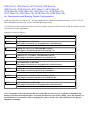
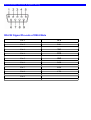
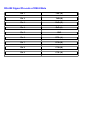
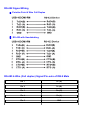
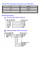
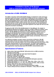
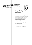
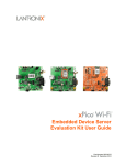
Hardware Setting and Mode Configuration
Outside the unit, there are sixteen 4-pin DIP switches which are set to select the mode of operation. You will
need to set the switch settings to RS-232 mode, or RS-422, or RS-485 mode as per the requirements of your
application.
You need to install driver first, prior to hardware installation. After the setting of DIP switches and connecting
power cord to the adapter, you then plug the adapter to USB port to start driver installation.
The Mode Block Configuration Settings are listed as follows:
SW1 (Port-1), SW2 (Port-2), SW3 (Port-3), SW4 (Port-4),
SW5 (Port-5), SW6 (Port-6), SW7 (Port-7), SW8 (Port-8),
SW9 (Port-9), SW10 (Port-10), SW11 (Port-11), SW12 (Port-12),
SW13 (Port-13), SW14 (Port-14), SW15 (Port-15), SW16 (Port-16)
Operation Mode
S1
S2
S3
S4
RS-232
Standard RS-232 Mode
OFF ON
ON
ON
RS-422
4 wire with Handshaking
ON
ON
ON
RS-485
Full Duplex (4 wire)
ON OFF ON
ON
Half Duplex (2 wire)
- with Echo
ON OFF OFF ON
Half Duplex (2 wire)
- without Echo
ON OFF OFF OFF
ON
JP5 (Port-1), JP6 (Port-2), JP7 (Port-3), JP8 (Port-4)
JP9 (Port-5), JP10 (Port-6), JP11 (Port-7), JP12 (Port-8)
JP13 (Port-9), JP14 (Port-10), JP15 (Port-11), JP16 (Port-12),
JP17 (Port-13), JP18 (Port-14), JP19 (Port-15), JP20 (Port-16)
for Termination and Biasing Option Configuration
Inside the unit, there are sixteen 2 x 7 (14 pin) header blocks which are jumpered to enable Tx, Rx, CTS 120
Ohm termination resistors and Tx, Rx 750 Ohm BIASing resistor.
You will need to open up the metal case and set the jumper setting for RS-422 mode or RS-485 mode as per the
requirements of your application.
Settings are listed as follows:
Jumper
Function
01.02.11
Tx Termination of 120 Ohm.
This jumper should always be populated for RS-485 mode.
3-4
Pull-up Tx+ to VCC by 750 Ohm Bias resistor.
This jumper should be populated for pull-up Tx+.
5-6
Pull-down Tx- to GND by 750 Ohm Bias resistor.
This jumper should be populated for pull-down Tx- .
7-8
Rx Termination of 120 Ohm.
This jumper should always be populated for RS-422 mode.
09.10.11
Pull-up Rx+ to VCC by 750 Ohm Bias resistor.
This jumper should be populated for pull-up Rx+
11.12.11
Pull-down Rx- to GND by 750 Ohm Bias resistor.
This jumper should be populated for pull-down Rx- .
13-14
CTS Termination of 120 Ohm.
This jumper should always be populated for RS-422 mode.
Note : Sometimes, when operating in RS-422 or RS-485, it is necessary to configure termination and
biasing of the data transmission lines. Generally this must be done in the cabling, since this depends on
the installation of connections. Before applying the option, check your cable specification for proper
impedance matching.
RS-232/422/485 Pin-outs & Signals Wiring
RS-232 Signal Pin-outs of DB-9 Male
Pin 1
DCD
Pin 2
RxD
Pin 3
TxD
Pin 4
DTR
Pin 5
GND
Pin 6
DSR
Pin 7
RTS
Pin 8
CTS
Pin 9
RS-422 Signal Pin-outs of DB-9 Male
Pin 1
TxD- (A)
Pin 2
TxD+(B)
Pin 3
RxD+(B)
Pin 4
RxD-(A)
Pin 5
GND
Pin 6
RTS- (A)
Pin 7
RTS+(B)
Pin 8
CTS+(B)
Pin 9
CTS- (A)
RS-422 Signal Wiring
Point-to-Point 4 Wire Full Duplex
RS-422 with Handshaking
RS-485 4-Wire (Full duplex) Signal Pin-outs of DB-9 Male
Pin 1
Tx- (A)
Pin 2
Tx+(B)
Pin 3
Rx+(B)
Pin 4
Rx-(A)
Pin 5
GND
RS-485 2-Wire (Half duplex) Signal Pin-outs of DB-9 Male
Pin 1
Data- (A)
Pin 2
Data+(B)
Pin 5
GND
RS-485 Signal Wiring
Point-to-Point 4-Wire Full Duplex
Multidrop RS-485 2-Wire Half-duplex