1
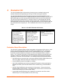
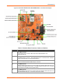
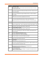
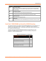
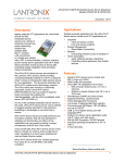
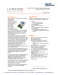
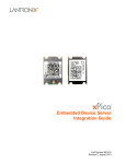
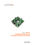
xPico Wi-Fi Embedded Device Server Evaluation Kit User Guide Part Number 900-643-R Revision D December 2014 Copyright and Trademark © 2014 Lantronix, Inc. All rights reserved. No part of the contents of this book may be transmitted or reproduced in any form or by any means without the written permission of Lantronix. Lantronix and xPico are registered trademarks of Lantronix, Inc. in the United States and other countries. U.S. patents: 7,309,260; 7,698,405; 8,024,446; 8,219,661. Additional patent(s) pending. Windows is a trademark of Microsoft Corporation. Wi-Fi is a registered trademark of the Wi-Fi Alliance Corporation. All other trademarks, servicemarks and trade names are the property of their respective owners. Warranty For details on the Lantronix warranty policy, please go to our Web site at www.lantronix.com/support/warranty. Contacts Lantronix, Inc. 167 Technology Drive Irvine, CA 92618, USA Phone: 949-453-3990 Fax: 949-453-3995 Technical Support Online: www.lantronix.com/support Sales Offices For a current list of our domestic and international sales offices go to the Lantronix web site at www.lantronix.com/about/contact. Disclaimer and Revisions Note: This product has been designed to comply with the limits for a Class B digital device pursuant to Part 15 of FCC and EN55022 Rules when properly enclosed and grounded. These limits are designed to provide reasonable protection against radio interference in a residential installation. This equipment generates, uses, and can radiate radio frequency energy, and if not installed and used in accordance with this guide, may cause interference to radio communications. Changes or modifications to this device not explicitly approved by Lantronix will void the user's authority to operate this device. The information in this guide may change without notice. The manufacturer assumes no responsibility for any errors that may appear in this guide. xPico® Wi-Fi® Embedded Device Server Evaluation Kit User Guide 2 Revision History Date July 2013 August 2013 August 2013 December 2014 Rev. A B C D Comments Initial document. Added xPico Wi-Fi module information. Updated pin number information. Updated Lantronix evaluation board information; added the new evaluation board schematic for SMT part with on-module antenna. xPico® Wi-Fi® Embedded Device Server Evaluation Kit User Guide 3 Table of Contents Copyright and Trademark ____________________________________________________ Warranty _________________________________________________________________ Contacts __________________________________________________________________ Disclaimer and Revisions ____________________________________________________ Revision History ____________________________________________________________ List of Figures _____________________________________________________________ List of Tables ______________________________________________________________ 1: Introduction 2 2 2 2 3 5 5 6 About this Guide ___________________________________________________________ 6 Additional Documentation ____________________________________________________ 6 2: Evaluation Kit 7 Evaluation Board Description _________________________________________________ 7 Serial Port 1 RS232/RS485 and Serial Port 2 RS232 Interface ______________________ 11 Antenna Port _____________________________________________________________ 14 Power Supply_____________________________________________________________ 15 LEDs ___________________________________________________________________ 16 Additional Headers ________________________________________________________ 17 Evaluation Board Schematic (XPW100100K-01 and XPCW1002100K)________________ 18 Evaluation Board Schematic (XPCW1003100K)__________________________________ 23 xPico® Wi-Fi® Embedded Device Server Evaluation Kit User Guide 4 List of Figures Figure 2-1 xPico Wi-Fi Evaluation Board XPW100100K-01 Connectors and Jumpers ______ 8 Figure 2-2 xPico Wi-Fi SMT Evaluation Board XPW100300K – Connectors and Jumpers _ 9 Figure 2-3 JP8, JP9, and JP17 Headers _______________________________________ 14 Figure 2-4 Evaluation Board Schematic for XPW100100K-01 and XPCW1002100K, Part 1 of 5 _____________________________________________ 18 Figure 2-5 Evaluation Board Schematic for XPW100100K-01 and XPCW1002100K, Part 2 of 5 _____________________________________________ 19 Figure 2-6 Evaluation Board Schematic for XPW100100K-01 and XPCW1002100K, Part 3 of 5 _____________________________________________ 20 Figure 2-7 Evaluation Board Schematic for XPW100100K-01 and XPCW1002100K, Part 4 of 5 _____________________________________________ 21 Figure 2-8 Evaluation Board Schematic for XPW100100K-01 and XPCW1002100K, Part 5 of 5 _____________________________________________ 22 Figure 2-9 Evaluation Board Schematic for XPCW1003100K, Part 1 of 7 ______________ 23 Figure 2-10 Evaluation Board Schematic for XPCW1003100K, Part 2 of 7 _____________ 24 Figure 2-11 Evaluation Board Schematic for XPCW1003100K, Part 3 of 7 _____________ 25 Figure 2-12 Evaluation Board Schematic for XPCW1003100K, Part 4 of 7 _____________ 26 Figure 2-13 Evaluation Board Schematic for XPCW1003100K, Part 5 of 7 _____________ 27 Figure 2-14 Evaluation Board Schematic for XPCW1003100K, Part 6 of 7 _____________ 28 Figure 2-15 Evaluation Board Schematic for XPCW1003100K, Part 7 of 7 _____________ 29 List of Tables Table 2-1 xPico Wi-Fi Evaluation Kit Contents____________________________________ 7 Table 2-2 Evaluation Board Connectors, Header and Switches ______________________ 9 Table 2-3 RS-232 Signals on J3 Serial Port_____________________________________ 11 Table 2-4 RS-422 4-Wire Signals on J3 Serial Port _______________________________ 12 Table 2-5 RS-485 2-Wire Signals on J3 Serial Ports ______________________________ 12 Table 2-6 JP11 and JP12 Jumper Settings for Serial Port 1 (J3) ____________________ 12 Table 2-7 JP18 Serial Port 2 RS232 Connections ________________________________ 12 Table 2-8 JP17 Serial Port 1 Flow Control Break Out Header _______________________ 13 Table 2-9 JP8 and JP9 Port 2 Serial or USB/Serial Selection Headers ________________ 13 Table 2-10 Evaluation Board Power Options ____________________________________ 15 Table 2-11 LEDs Signals ___________________________________________________ 16 Table 2-12 JP6 LED Header Connections (XPW100100K-01 and XPCW1002100K) ____ 17 Table 2-13 JP6 LED Header Connections (XPW100300K) _________________________ 17 Table 2-14 Additional Headers ______________________________________________ 17 xPico® Wi-Fi® Embedded Device Server Evaluation Kit User Guide 5 1: Introduction About this Guide This guide provides the information needed to use the Lantronix® xPico® embedded device server with the evaluation kit. The intended audience is the engineers responsible for integrating the xPico and xPico Wi-Fi into their product. In this document, “xPico” refers to all xPico Ethernet only modules, “xPico Wi-Fi” refers to all xPico modules which have a Wi-Fi interface and “xPico Wi-Fi SMT” refer to those modules with a surface mount mounting. Notes: Everything required to evaluate the xPico turnkey application is provided in the Evaluation Kit. See xPico Wi-Fi Evaluation Kit Contents for more information. Additional Documentation Visit the Lantronix web site at www.lantronix.com/support/documentation for the latest documentation and the following additional documentation. Document Description xPico Wi-Fi Embedded Device Server Evaluation Kit Quick Start Guide Instructions for getting the xPico module up and running on the evaluation board. xPico Embedded Device Server Integration Guide Provides information for integrating the xPico module on a customer platform. xPico Wi-Fi SMT Embedded Device Provides information for integrating the xPico Wi-Fi SMT module on Server Integration Guide a customer platform. xPico Embedded Device Server Product Brief Provides a quick reference to xPico technical specifications. xPico Wi-Fi Embedded Device Server Product Brief Provides a quick reference to xPico Wi-Fi technical specifications. xPico Wi-Fi SMT Embedded Device Provides a quick reference to xPico Wi-Fi SMT technical Server Product Brief specifications. xPico Wi-Fi SMT Embedded Device Provides a detailed reference to xPico Wi-Fi SMT technical Server Datasheet specifications. xPico Embedded Device Server User Guide Provides information needed to configure, use, and build applications on the xPico. xPico Wi-Fi Embedded Device Server User Guide Provides information needed to configure, use, and build applications on the xPico Wi-Fi. xPico® Wi-Fi® Embedded Device Server Evaluation Kit User Guide 6 2: Evaluation Kit The xPico Embedded Device Server family of products can be evaluated using several available Evaluation Kits depending upon the type of PCB mounting and interface. The xPico Embedded Device Server Evaluation Kit (part number XPW100100K-01) is for evaluating the xPico and xPico Wi-Fi modules with 40-pin connector interface. The xPico Wi-Fi SMT module with on module antenna (XPCW1003100) module uses the XPCW1003100K. The xPico Wi-Fi SMT module with U.FL connector comes on a carrier board that uses the same board as the used for the connector versions of the module. This Evaluation Kit is the XPCW1002100K. All of these kits can help you get familiar with your xPico module so that you may understand how to integrate your xPico embedded device server into a given product design. Table 2-1 xPico Wi-Fi Evaluation Kit Contents XPW100100K-01 XPCW1002100K XPCW1003100K xPico Wi-Fi Module xPico Evaluation Board 5V Wall Adaptor xPico Mounting Quick Clip 40-pin Connector Sample 2 dBi Swivel Type Antenna and U.FL to RP SMA Cable 2.5 dBi PCB Strip Antenna with U.FL cable xPico Wi-Fi SMT W1002 Module on Carrier Board xPico Evaluation Board 5V Wall Adaptor 2 dBi Swivel Type Antenna and U.FL to RP SMA Cable 2.5 dBi PCB Strip Antenna with U.FL cable xPico Wi-Fi SMT W1003 Module xPico SMT Evaluation Board 5V Wall Adaptor Evaluation Board Description The xPico Wi-Fi evaluation board provides a test platform for the Lantronix xPico device server products. The evaluation board uses either 5V power from a USB device port connector or power supplied to the Ethernet connector via PoE (XPW100100K-01 only). The evaluation board also provides a header for connection to a 2.2V to 5.5V external source, such as a battery. The Evaluation Kit includes a 5V wall adapter with a USB plug to allow powering the evaluation board from a standard power strip. The evaluation board includes all necessary regulators to power the 3.3V xPico module. The evaluation board has the following features: ♦ One DB9 serial port connector with a multi-protocol RS232, RS422, RS485 transceiver at rates up to 1Mbps. Serial port modes are configured by on-board jumpers. ♦ A second RS232 serial port is available on a header. ♦ One RJ45 10/100 Ethernet port with an integrated PoE regulator to allow powering from standard POE PSE. (POE works with Ethernet xPico modules only) ( XPW100100K-01 only) ♦ One Mini-Type B USB device port connector for 5V input power. This port also has an integrated USB-to-serial converter. The USB-to-serial converter can be connected to the xPico second serial port via a board jumper setting. ♦ A second Mini-type B USB device port is available for connection to the xPico module USB device port. (Currently available on xPico Wi-Fi only) xPico® Wi-Fi® Embedded Device Server Evaluation Kit User Guide 7 2: Evaluation Kit ♦ LEDs for the xPico Ethernet, WLAN, and System status outputs along with two additional LEDs that can be driven via jumper wire are provided. ♦ Access to all logic level IO signals on the xPico via header pins for measurements and connections to other places. The figure below shows the xPico evaluation board and highlights all of the various connectors and configuration jumpers. The following table lists each of the connectors and jumper headers along with their function. Further description and pin assignments are included in subsequent sections. Figure 2-1 xPico Wi-Fi Evaluation Board XPW100100K-01 Connectors and Jumpers xPico® Wi-Fi® Embedded Device Server Evaluation Kit User Guide 8 2: Evaluation Kit Figure 2-2 xPico Wi-Fi SMT Evaluation Board XPW100300K – Connectors and Jumpers Table 2-2 Evaluation Board Connectors, Header and Switches Ref Des. Connector/Header Function J1 xPico Module Socket 40 pin socket for xPico module or SMT carrier board. XPW100100K-01 and XPCW1002100K only. J2 RJ45 Connector 10/100Mbps Ethernet connector. PoE powered device port. Functional for xPico Ethernet modules. XPW100100K-01 and XPCW1002100K only. J3 Serial Port 1 DB9 Standard RS232/RS422/RS485 DB9 serial port connector. J5 Mini USB Connector Standard USB device port that can be used to power the evaluation board and/or drive the evaluation board USB-to-serial converter. The USB serial port converter can be connected to the module second serial port via a jumper setting. J6 Mini USB Connector Standard USB device port that can be used to power the evaluation board and/or drive the xPico Module USB device port. Functional for xPico Wi-Fi module. xPico® Wi-Fi® Embedded Device Server Evaluation Kit User Guide 9 2: Evaluation Kit Ref Des. JP1 Connector/Header Function Module Power Jumper Allows for voltage measurement of the xPico module current sense resistor. The current sense resistor is 0.301 ohms. JP3 Default Button Jumper Allows access to module reset to default signal and SW1 push button. Install to use SW1 as reset to default button. JP4 HW Reset Button Jumper Allows access to module HW reset signal and SW2 push button. Install to use SW2 as HW reset button. JP5 Configurable Pin Header Provides access to xPico module configurable pins CP1 to CP8 JP6 Ethernet/WLAN LED Header Allows access to Ethernet/WLAN LED signals. Install to drive evaluation board Ethernet/WLAN LEDs with module LED signals. XPW100100K-01 and XPCW1002100K only. JP6 Reserved for future Ethernet activity LED (XPCW1003100k) JP7 Spare LED Header Provides two additional LEDs. Jumper to desired active low signal to light LED6 and LED7 JP8 Serial Port 2 TX Source Header Install jumper to select between DB9 serial port or USB-to-serial. JP9 Serial Port 2 RX Source Header Install jumper to select between DB9 serial port or USB-to-serial. JP10 WLAN LED Header (XPCW1003100K) Allows access to WLAN LED signal. Install to drive evaluation board WLAN LEDs with module LED signals. JP11 Serial Port 1 RS232/RS422/RS485 Mode Jumper Leave open for RS232 mode. Install for RS422/RS485 JP12 Serial Port 1 RS422/RS485 Mode Jumper Leave open for RS232 or 4-wire mode. Install for 2-wire mode. JP14 3.3V Power Header Provides access to the internal 3.3V power rail. JP15 Ground Header Provides access to the internal signal ground rail. JP16 WAKE Header Allows access to module WAKE signal and SW4 push button. Install to use SW4 to wake up the xPico module when in low power modes. JP17 Serial Port 1 Breakout Header Install jumpers to connect xPico Serial Port 1 flow control signals to the RS232/RS422/RS485 transceiver for Serial Port 1. JP18 Serial Port 2 Signal Header Provides access to the module second serial port. The signals on this header have been buffered by an RS232 transceiver. xPico® Wi-Fi® Embedded Device Server Evaluation Kit User Guide 10 2: Evaluation Kit Ref Des. JP19 Connector/Header Function External Power Header Provides connection point for an external 2.2V to 5.5V power source, such as a battery. This is connected to a 3.3V step up/down regulator that will power the evaluation board and module circuitry. SW1 Module Reset to Default When pushed asserts the xPico module reset to default function. SW2 Module Hardware Reset When pushed asserts the xPico module hardware reset to reboot the module. SW3 Board Power Switch Switches ON or OFF the logic power rails. SW4 WAKE Button When pushed asserts the xPico module WAKE signal. Functional for xPico Wi-Fi module only. Serial Port 1 RS232/RS485 and Serial Port 2 RS232 Interface The evaluation board has one multiprotocol RS-232/RS422/RS485 port and one RS232 port for connection to the xPico internal UARTs. Serial port 1 is a DB9 type connector labeled J3. Serial Port 2 is a 3-pin header, JP18. The null modem cable can be used to connect J3 directly to a standard PC RS232 serial port. The tables below list the RS232/RS422/RS485 signals and corresponding pins on the evaluation board DB9 connectors. All signals at J3 are level-shifted by a multiprotocol transceiver. JP18 is an RS232 port only. Table 2-3 RS-232 Signals on J3 Serial Port xPico Evaluation Board PIN FUNCTION SERIAL PORTS DB9 Pin # TX_232 (Data Out) 3 RX_232 (Data In) 2 CTS_232 (HW Flow Control Input) 8 RTS_232 (HW Flow Control Output) 7 DTR_232 (Modem Control Output) 4 DCD_232 (Modem Control Input) 1 GND (Ground) 5 xPico® Wi-Fi® Embedded Device Server Evaluation Kit User Guide 11 2: Evaluation Kit Table 2-4 RS-422 4-Wire Signals on J3 Serial Port xPico Evaluation Board PIN FUNCTION SERIAL PORTS DB9 Pin # TX- (Data Out) 3 RX+ (Data In) 2 TX+ (Data Out) 7 RX- (Data In) 8 GND (Ground) 5 Table 2-5 RS-485 2-Wire Signals on J3 Serial Ports xPico Evaluation Board PIN FUNCTION SERIAL PORTS DB9 Pin # TX-/RX- (Data IO) 3 TX+/RX+ (Data IO) 7 GND (Ground) 5 The J3 DB9 port is configured for RS232, RS422 (4-wire), or RS485 (2-wire) by jumper settings on JP11 and JP12. Table 2-5 lists the correct jumper installation for each mode. Table 2-6 JP11 and JP12 Jumper Settings for Serial Port 1 (J3) xPico Evaluation Board Serial Port 1 Mode (J3) JP11 JP12 RS232 (Default) OUT OUT RS485 2-wire IN IN RS422 4-wire IN OUT JP18 is for connection to the module second serial port through an RS232 transceiver. The pin assignments for JP18 are listed below. Table 2-7 JP18 Serial Port 2 RS232 Connections xPico Evaluation Board Serial Port 2 JP18 pin TX RS232 output 1 Signal Ground 2 RX RS232 input 3 All of the xPico module serial port signals can be used as configurable pins. Jumper headers JP17, JP8 and JP9 have been included to allow for each of the serial port signals to be connected or disconnected from the serial port transceiver. The tables below list the JP17, JP8, and JP9 serial port signal connections. Install jumper or remove as needed for desired function. In addition, the second serial port on the xPico module can be connected to either the serial port on J18 or to the USB on J5 via the on board USB-to-serial converter. Jumpers JP8 and JP9 allow for the selection of sending the JP18 or J5 USB-to-Serial converter to Serial Port 1. xPico® Wi-Fi® Embedded Device Server Evaluation Kit User Guide 12 2: Evaluation Kit In order to access the unit through the J5 USB port, you will need to install the USB-to-serial VCP driver from FTDI on your PC. It is available in the installation directory of DeviceInstaller and later versions, for installation. It can also be obtained from the FTDI website provided below. Once installed, you will be able to view the xPico boot messages as well as provide command inputs through any PC terminal program, such as Tera Term. Download FTDI USB-to-serial drivers at this website: http://www.ftdichip.com/Drivers/VCP.htm Table 2-8 JP17 Serial Port 1 Flow Control Break Out Header xPico Module J1 Pin xPico Module PIN FUNCTION JP17 Pin # JP17 Pin # JP3 Evaluation Board Function 10 Serial Port TX (output) 2 1 RS232, RS485 TX 7 Serial port RX (input) 4 3 RS232, RS485 RX 5 Serial port RTS1 or TX enable or configurable pin 6 5 RS232 RTS, RS485 TX Enable 28 Configurable pin CP3 or Serial port DTR1 8 7 RS232 DTR 16 Serial port CTS1 or configurable pin 9 RS232 CTS 30 Configurable pin CP4 or Serial port DCD1 12 11 RS232 DCD 10 Note: JP17 jumpers 7 to 8 and 11 to 12 are not installed by default. All other JP17 jumpers are installed at the factory. Table 2-9 JP8 and JP9 Port 2 Serial or USB/Serial Selection Headers Serial Port 1 External Connection JP8 JP9 Serial Port 2 to JP18 for RS232 (Default) Jumper pins 1 to 2 Jumper pins 1 to 2 Serial Port 2 to J5 USB via USB-to-serial converter Jumper pins 2 to 3 Jumper pins 2 to 3 xPico® Wi-Fi® Embedded Device Server Evaluation Kit User Guide 13 2: Evaluation Kit Figure 2-3 JP8, JP9, and JP17 Headers Antenna Port The xPico evaluation boards (XPW100100K-01 and XPCW1002100K ) includes a bracket for mounting the U.FL to Reverse Polarity SMA RF cable included with the kit. Follow the procedure below when installing the antenna cable. The same procedure applies when using the PCB strip antenna, with the exception that the swivel antenna does not need to be connected to the RF cable. 1. Attach the U.FL cable to the antenna prior to installing the xPico Wi-Fi module on the J1 socket. 2. Attach the plastic mounting clip to the module. 3. Install the module/SMT module on carrier board into the J1 socket. 4. Install the external antenna to the SMA end of the RF cable. Note: Install or remove the antenna connections only while the module is powered off. xPico® Wi-Fi® Embedded Device Server Evaluation Kit User Guide 14 2: Evaluation Kit Ethernet Port The xPico evaluation board XPW100100K-01 includes one RJ45 with on-board magnetics for connection to the xPico module 10/100Mbps Ethernet interface. Connector J2 is the Ethernet port. Note: The Ethernet port is functional for xPico Ethernet modules only. Power Supply The evaluation board provides several options for input power. Included with the kit is a 5V wall adapter. The 5V wall adapter plugs into USB connector J5. In addition to powering from the wall adapter, the evaluation board can be powered from a standard PC USB Host port by connecting a USB cable between the PC and J5 or J6. The XPW100100K-01 evaluation board can also be powered via Power-Over-Ethernet (PoE). The integrated PoE regulator accepts power from the Ethernet port on J2. The final option is to connect DC power to header JP19. Table 2-10 Evaluation Board Power Options Input Power Option Description 5V Wall Cube Connect 5V wall cube to J5 or J6 USB port. Note: USB-to-serial and USB device port not available in this option. USB Connect J5 or J6 USB power to a PC USB Host Port. Note: For J5 connection, PC Host port can communicate with serial port 2 via on-board USB-to-serial converter. See Table 2-1 for JP8 and JP9 jumper pin selection. Note: For J6 connection, PC can communicate with module device port on xPico Wi-Fi module. PoE Connect J2 Ethernet port to external PoE PSE switch or PoE injector. XPW100100K-01 only JP19 Connect a 2.2V to 5.5V DC power source to JP19 pin 1 (+). Connect the power supply DC ground to JP19 pin 2 (-). xPico® Wi-Fi® Embedded Device Server Evaluation Kit User Guide 15 2: Evaluation Kit LEDs The xPico evaluation board includes several LEDs for signal and unit status. The table below lists all of the LEDs and their functions. Table 2-11 LEDs Signals J1 Pin LED Ref Design Color LED Function 20 LED1 Orange xPico Status LED blinks with patterns indicating module status. See the xPico user guide for a full description of the status LED blink patterns. 4 LED2 Orange Ethernet Link/WLAN Status LED is ON when the device is associated with an access point (on the STA interface.) LED is OFF when the device is not associated with an access point. LED is ON when there is a valid Ethernet link (XPW100100K-01) 6 LED3 Orange Ethernet Speed (XPW100100K-01) LED is ON when Ethernet is in 100Mbps mode, xPico with Ethernet only. 8 LED4 Orange Ethernet Activity (XPW100100K-01) LED blinks when there is activity on the Ethernet port, xPico with Ethernet only. 14 LED5 Orange Ethernet Duplex (XPW100100K-01) LED is ON when Ethernet is in half duplex mode, xPico with Ethernet only. LED6 Orange Spare LED LED is ON when JP7 pin 1 is driven low LED7 Orange Spare LED LED is ON when JP7 pin 2 is driven low. 10 LED8 Green Serial Port 1 TX Activity LED is ON for activity on the Serial Port 1 transmit line 7 LED8 Orange Serial Port 1 RX Activity LED is ON for activity on the Serial Port 1 receive line 25 LED9 Green Serial Port 2 TX Activity LED is ON for activity on the Serial Port 2 transmit line 23 LED9 Orange Serial Port 2 RX Activity LED is ON for activity on the Serial Port 2 receive line LED10 Blue 3.3V Power LED LED is ON when the evaluation board power supply is generating 3.3V xPico® Wi-Fi® Embedded Device Server Evaluation Kit User Guide 16 2: Evaluation Kit Table 2-12 JP6 LED Header Connections (XPW100100K-01 and XPCW1002100K) Jumper Position Description Pins 1 to 2 Install to connect module Ethernet link/WLAN status signal to LED2 Pins 3 to 4 Install to connect module Ethernet Speed signal to LED3 Pins 5 to 6 Install to connect module Ethernet Activity signal to LED4 Pins 7 to 8 Install to connect module Ethernet Duplex signal to LED5. Remove when using xPico Wi-Fi module to prevent conflict with module wake up signal. This jumper is not stuffed by default. Table 2-13 JP6 LED Header Connections (XPW100300K) Jumper Position Description Pins 1 to 2 Install to connect module WLAN status signal to LED2 Additional Headers The table below lists the pin functionality of the additional evaluation board headers. Table 2-14 Additional Headers J1 Pin Header Pin Signal Function 36 JP3 pin 1 Module reset to defaults (active low) Install jumper (JP3 pins 1 to 2) to use SW1 for asserting default function. 38 JP4 pin 1 Module hardware reset (active low) Install jumper (JP4 pins 1 to 2) to use SW2 for asserting hardware reset. 14 JP16 pin 1 Module wake up (rising edge Install jumper (JP16 pins 1 to 2) to use SW4 for asserting module wake up. triggered) Do not install when using xPico (wired) Ethernet Duplex LED signal. 35 JP5 pin 1 CP1, configurable pin Test point 26 JP5 pin 2 CP2, configurable pin Test point 28 JP5 pin 3 CP3, configurable pin Test point 30 JP5 pin 4 CP4, configurable pin Test point 32 JP5 pin 5 CP5, configurable pin Test point 34 JP5 pin 6 CP6, configurable pin Test point 27 JP5 pin 7 CP7, configurable pin Test point 3 JP5 pin 8 CP8, configurable pin Test point xPico® Wi-Fi® Embedded Device Server Evaluation Kit User Guide 17 2: Evaluation Kit Evaluation Board Schematic (XPW100100K-01 and XPCW1002100K) Figure 2-4 Evaluation Board Schematic for XPW100100K-01 and XPCW1002100K, Part 1 of 5 xPico® Wi-Fi® Embedded Device Server Evaluation Kit User Guide 18 2: Evaluation Kit Figure 2-5 Evaluation Board Schematic for XPW100100K-01 and XPCW1002100K, Part 2 of 5 xPico® Wi-Fi® Embedded Device Server Evaluation Kit User Guide 19 2: Evaluation Kit Figure 2-6 Evaluation Board Schematic for XPW100100K-01 and XPCW1002100K, Part 3 of 5 xPico® Wi-Fi® Embedded Device Server Evaluation Kit User Guide 20 2: Evaluation Kit Figure 2-7 Evaluation Board Schematic for XPW100100K-01 and XPCW1002100K, Part 4 of 5 xPico® Wi-Fi® Embedded Device Server Evaluation Kit User Guide 21 2: Evaluation Kit Figure 2-8 Evaluation Board Schematic for XPW100100K-01 and XPCW1002100K, Part 5 of 5 xPico® Wi-Fi® Embedded Device Server Evaluation Kit User Guide 22 2: Evaluation Kit Evaluation Board Schematic (XPCW1003100K) Figure 2-9 Evaluation Board Schematic for XPCW1003100K, Part 1 of 7 xPico® Wi-Fi® Embedded Device Server Evaluation Kit User Guide 23 2: Evaluation Kit Figure 2-10 Evaluation Board Schematic for XPCW1003100K, Part 2 of 7 xPico® Wi-Fi® Embedded Device Server Evaluation Kit User Guide 24 2: Evaluation Kit Figure 2-11 Evaluation Board Schematic for XPCW1003100K, Part 3 of 7 xPico® Wi-Fi® Embedded Device Server Evaluation Kit User Guide 25 2: Evaluation Kit Figure 2-12 Evaluation Board Schematic for XPCW1003100K, Part 4 of 7 xPico® Wi-Fi® Embedded Device Server Evaluation Kit User Guide 26 2: Evaluation Kit Figure 2-13 Evaluation Board Schematic for XPCW1003100K, Part 5 of 7 xPico® Wi-Fi® Embedded Device Server Evaluation Kit User Guide 27 2: Evaluation Kit Figure 2-14 Evaluation Board Schematic for XPCW1003100K, Part 6 of 7 xPico® Wi-Fi® Embedded Device Server Evaluation Kit User Guide 28 2: Evaluation Kit Figure 2-15 Evaluation Board Schematic for XPCW1003100K, Part 7 of 7 xPico® Wi-Fi® Embedded Device Server Evaluation Kit User Guide 29