1
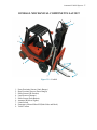
JNM Technologies
Fluffy Bunny-3000 Series
Automatic Forklift
5/29/2008
DEVRY UNIVERSITY-FREMONT
ELECTRONICS ENGINEERING TECHNOLOGY PROGRAM
AUTOMATIC
FORKLIFT SYSTEM
Prepared by:
PROJECT MANAGER/ID#:
NICHOLAS LARSEN / D02051830
HARDWARE ENGINEER/ID#: JOSHUA QUINTERO / D02113148
SOFTWARE ENGINEER/ID#: MAI ZOUA VANG / D02142100
Prepared for:
TECHNICAL ADVISOR: DR. DUMITRU M. ARMULESCU
GENERAL ED. ADVISOR: PROF. KIM MAHLER
March 22, 2008
Automatic Forklift System
DEVRY UNIVERSITY-FREMONT
ELECTRONICS ENGINEERING TECHNOLOGY PROGRAM
EET-404 / FINAL REPORT:
EVALUATION SHEET
PROJECT MANAGER/ ID#:
NICHOLAS LARSEN / D02051830
HARDWARE ENGINEER/ ID#:
JOSHUA QUINTERO / D02113148
SOFTWARE ENGINEER/ ID#:
MAI ZOUA VANG / D02142100
PROJECT TITLE: AUTOMATIC FORKLIFT SYSTEM
GRADING CRITERIA
MARK
OUT OF
MAXIMUM
MARKS
STYLE, ORGANIZATION, CLARITY
10
SPELLING, GRAMMAR, CONCISENESS
5
LABELING, FIGURES, TABLES, PAGES
5
TIME MANAGEMENT
10
TECHNICAL CONTENT / CORRECTNESS
70
TOTAL
DATE:
________________
GENERAL ED. ADVISOR NAME:
Professor Kim Mahler
GENERAL ED. ADVISOR SIGNATURE:
_____________________________
100
ii
Automatic Forklift System iii
AUTHORS’ DECLARATION
We hereby declare that we are the sole authors of this senior technical project. We also authorize
DeVry University-Fremont to lend this project to other institutions or individuals for the purpose
of scholarly research.
We further authorize DeVry University-Fremont to reproduce this project by photocopying or by
other means, in total or parts, at the request of other institutions or individuals for the purpose of
scholarly research.
Project Manager:
Nicholas Larsen
Hardware Engineer: Joshua Quintero
Software Engineer:
Mai Zoua Vang
Automatic Forklift System iv
ACKNOWLEDGEMENTS
The authors would like to give special thanks to Dr. Dumitru M. Armulescu, Dr. Ajeet Singh, Dr.
Mostafa Mortezaie, and Dr. Syed Rashdee for providing technical expertise and guidance
throughout the term, making possible the successful finalization of this senior project.
Also, the authors would like to recognize the General Education Advisor Prof. Kim Mahler for
her valuable advice and contribution to the improvement of the formal aspect of the senior
project written report and oral presentation.
Finally, the authors would like to recognize Deans Michael Zohourian, and Tara Mills-Welch for
their continuous effort to ensure better conditions for EET-404 senior project activities.
Automatic Forklift System
v
ABSTRACT
The Automatic Forklift System (AFS) is designed to make the process of stocking warehouses
safer and more efficient. With current manually operated forklifts, employees are at risk of
injury. Employers also spend a lot of money on insurance and paying multiple employees to
operate forklifts in their warehouses. The AFS will limit the need for employees to operate
forklifts manually. This will not only cut down on long term employer costs, but will reduce the
chance of injury among employees as well.
We built a 1/6th scale prototype of a single AFS. This model takes pallets to and from the
docking area and different aisles. The user chooses what they want the forklift to do by way of
the hand-held user interface. The commands from the user are sent wirelessly to the forklift. It
then drives itself along predetermined paths, picks up the pallet, and brings it to the desired
location. When finished, it returns “home” where it awaits another command. “Home” is the
aisle were the forklift parks while waiting for commands; on a full scale electric forklift this
would also be where it pulls into its charger.
For safety purposes, the forklift is equipped with a tilt sensor, a wireless camera, front and rear
proximity sensors, and emergency shut off buttons. The tilt sensor detects if the forklift tips over;
if this happens, the forklift stops and tells the user via the user control that the forklift has tipped
over. Once the forklift has been righted, the user may then choose to proceed, or go back home.
The front and rear proximity sensors detect if an object is in the path of the forklift; if this
happens, the forklift stops and the user control asks the user if it is safe to proceed. The user may
check the video feed that shows the area immediately in front of the forklift and determine if the
area is clear. Emergency shutoff buttons are located on three sides of the forklift; in case all other
safety options fail, someone can push one of the buttons which physically disconnects the power
to the motors.
Automatic Forklift System vi
TABLE OF CONTENTS
Authors’ Declaration ...................................................................................................................... iii
Acknowledgements ........................................................................................................................ iv
Abstract ............................................................................................................................................v
List of Tables ................................................................................................................................ vii
List of Figures .............................................................................................................................. viii
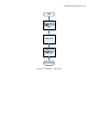
Chapter 1 INTRODUCTION
1.1 Project Scope ..........................................................................................................................1
1.2 Target Users ...........................................................................................................................1
1.3 Future Enhancements .............................................................................................................2
Chapter 2 ECONOMIC ANALYSIS
2.1 Market Analysis .....................................................................................................................3
2.2.0 Budget Analysis ..................................................................................................................4
2.2.1 Materials ..............................................................................................................................5
2.2.2 Labor Cost ...........................................................................................................................5
2.3 Gantt Chart .............................................................................................................................8
Chapter 3 HARDWARE DESIGN
3.1 Mechanical Design ...............................................................................................................12
3.2 Electrical Design ..................................................................................................................15
Chapter 4 SOFTWARE DESIGN
4.1 User Interface .......................................................................................................................23
4.2 Forklift ..................................................................................................................................41
Chapter 5 SERVICE MANUAL
Service Manual ...........................................................................................................................50
REFERENCES
APPENDIX A
APPENDIX B
APPENDIX C
Automatic Forklift System vii
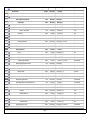
LIST OF TABLES
Table 1: Market Analysis .................................................................................................................3
Table 2: Material Cost Estimate ......................................................................................................5
Table 3: Actual Cost of Materials ....................................................................................................6
Table 4: Yearly Salaries ...................................................................................................................7
Table 5: Labor Cost .........................................................................................................................7
Table 6: Pin Descriptions for LCD ................................................................................................18
Table 7: LCD Command Codes.....................................................................................................19
Table 8: Transmission Values........................................................................................................24
Table 9: Troubleshooting ...............................................................................................................68
Automatic Forklift System viii
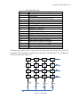
LIST OF FIGURES
Figure 1: Labor vs Material Cost Pie Chart .....................................................................................4
Figure 2: Labor Cost Pie Chart ........................................................................................................8
Figure 3: Mechanical Top View ....................................................................................................12
Figure 4: Steering Top View..........................................................................................................12
Figure 5: AFS Sensor Location......................................................................................................13
Figure 6: Fork Sensor Location 1 ..................................................................................................13
Figure 7: Fork Sensor Location 2 ..................................................................................................14
Figure 8: Intersection .....................................................................................................................14
Figure 9: User Interface Hardware Block Diagram .......................................................................15
Figure 10: Forklift Hardware Block Diagram ...............................................................................16
Figure 11: User Interface Hardware Circuit Diagram ...................................................................17
Figure 12: Keypad..........................................................................................................................19
Figure 13: Forklift Hardware Circuit Diagram ..............................................................................20
Figure 14: User Interface ...............................................................................................................26
Figure 15: Function - Int_LCD ......................................................................................................27
Figure 16: Function - Interupt ........................................................................................................28
Figure 17: Function - Menu ...........................................................................................................29
Figure 18.1: Function - Check_Keys .............................................................................................30
Figure 18.2: Function - Check_Keys (cont.) .................................................................................31
Figure 19.1: Function - Key_Table ................................................................................................32
Figure 19.2: Function - Key_Table (cont.) ....................................................................................33
Figure 20: Function - Arrow ..........................................................................................................34
Figure 21.1: Function - Screen.......................................................................................................35
Figure 21.2: Function - Screen (cont.) ...........................................................................................36
Figure 22: Function - Out_LCD_String .........................................................................................37
Figure 23: Function - Out_LCD ....................................................................................................38
Figure 24: Function - Clear ............................................................................................................39
Figure 25: Function - Transmit ......................................................................................................40
Automatic Forklift System ix
LIST OF FIGURES
(Continued)
Figure 26.1: Forklift .......................................................................................................................42
Figure 26.2: Forklift (cont.) ...........................................................................................................43
Figure 26.3: Forklift (cont.) ...........................................................................................................44
Figure 26.4: Forklift (cont.) ...........................................................................................................45
Figure 27: Function - Tilt_Check ..................................................................................................46
Figure 28: Function - Lower_Fork ................................................................................................47
Figure 29: Function - Lift_Fork .....................................................................................................48
Figure 30: Function - Set_neutral ....................................................................................................4
Figure 31: User Interface Hardware Block Diagram ....................................................................54
Figure 32: Forklift Hardware Block Diagram ...............................................................................54
Figure 33: User Interface Hardware Circuit Diagram ...................................................................55
Figure 34: Forklift Hardware Circuit Diagram ..............................................................................56
Figure 35.1: Forklift .......................................................................................................................57
Figure 35.2: Forklift (cont.) ...........................................................................................................58
Figure 36: User Interface ...............................................................................................................59
Figure 37: Intersection ...................................................................................................................60
Figure 38: H-Bridge .......................................................................................................................61
Figure 39: IR Boards ......................................................................................................................62
Figure 40: Ultrasonic Board I2C connection to PIC ......................................................................63
Figure 41: Keypad..........................................................................................................................64
Figure 42: IR Comparator Board ...................................................................................................65
Figure 43: 5V Regulator ................................................................................................................66
Figure 44: 18F452 PIC Microcontroller board ..............................................................................66
Figure 45: Wireless Zigbee ............................................................................................................67
CHAPTER ONE
INTRODUCTION
Automatic Forklift System
1
1.1
PROJECT SCOPE
The Automatic Forklift System (AFS) is designed to make the process of stocking efficient
while decreasing unnecessary work related spending. A one-sixth scale model forklift is being
used to demonstrate the feasibility of the project. An operator will control the system at a safe
distance away from the forklift, such as in a separate control room, decreasing the risk of workrelated injuries with a handheld user interface.
The Automatic Forklift System is capable of the following operations: receiving commands
from the operator, navigating through the modeled warehouse, retrieving and placing pallets at
desired locations. The AFS utilizes two microcontrollers called Programmable Interrupt
Controllers (PIC), many sensors, and various motors. The PICs, one in the forklift and one in
the user interface, are programmed with the required algorithms needed to run this project.
Several infrared (IR) sensors are used for navigation to follow painted lines on the ground, as
well as pallet detection and to see if the forklift falls over. Two ultrasonic range finders are
used to detect objects or people in front of or behind the forklift. Two momentary switches, one
in each fork, are used to detect a load on the forks. Servo motors are used for steering as well as
tilting the forks. Electric motors are used for driving the forklift forward and in reverse, and to
raise the forks. There is a camera mounted on the top of the forklift to give the user a visual aid
for tracking the forklift. And lastly, there are several emergency shut-off switches placed
around the forklift.
In this project there requires a project manager, hardware engineer, and software engineer. Nick
Larsen is the project manager, Joshua Quintero is the hardware engineer, and Mai Zoua Vang is
of software engineer.
1.2
TARGET USERS
The intended users of the AFS would be distributing centers, as well as any company with a
large warehouse that uses forklifts to move pallets. The ideal environment for this system
would be warehouses with little to no foot traffic that require a forklift to move pallets from
trucks to their respective shelves, or stacks, etc.
Employers will benefit from this system by saving money in the long run. An initial investment
in the AFS will reduce the cost of employing multiple forklift operators needed to keep up with
the inflow and outflow of large quantities of product. With this system, only one operator
would be needed to operate the AFS, and as a possible future enhancement, multiple systems.
As you can see, employers stand to benefit from this system.
With the AFS, the risk of injury to employees involving forklifts will be reduced, because there
will be no need for an operator on the forklift itself to steer it manually. Thus, the operator will
no longer be put into dangerous situations. This lowers the cost of workers’ comp. The AFS
eliminates the opportunity for human error that may have caused workplace accidents resulting
in property damage and bodily harm. This system offers the benefit of safety to employees.
Automatic Forklift System
2
1.3
FUTURE ENHANCEMENTS
With further resources and time we could implement a system that would be superior to today’s
methods. The AFS would be integrated with a database that keeps track of the inventories
through the use of RFID scanners to enter the pallets into the database before moving them. A
scale would be added to the forklift to track the weight of each pallet for shipping purposes and
to prevent overloading the weight capacity of the forklift. There could also be a manual
override for the user to manually operate the forklift for special cases. In the future, the system
could be able to operate multiple forklifts at any given time by adding to the software
algorithms. Laser navigation could be incorporated to eliminate the need of lines on the
warehouse floor. To implement these enhancements, a microprocessor with capabilities greater
than the PIC18F452 would be needed for higher order applications.
CHAPTER TWO
ECONOMIC ANALYSIS
Automatic Forklift System
3
2.1
MARKET ANALYSIS
There are at least a handful of companies that currently offer Automatic Guided Vehicle (AGV)
forklifts. The majority of AGVs utilize laser guidance or magnetic guidance systems. At first
we planned on using magnetic disk navigation, but due to the limitations in the magnetic
sensors encountered in the early testing stages, we decided to go with an IR sensor navigation
configuration instead. This will allow for a more reliable and accurate navigation system given
our time and resources. These other companies also offer manual control of their AGV. At the
moment we are not planning on incorporating a manual control into our forklift. All companies,
including ours, offer safety options, such as laser or mechanical bumpers that stop the AGV,
should something get in the way. Although this market has been well developed by multiple
companies, we believe that we can duplicate this technology, with limited means, and offer it at
a more affordable price as seen by Table 1.
Table 1: Market Analysis
Company
Transbotics
FMC Technologies
www.fmcsgvs.com www.transbotics.com
Savant
JNM
www.agvsystems.com Technologies
Navigation
System
Laser
Laser
Magnet Floor Tape
Infra Red
Manual
Control
Yes
Yes
Yes
No
Safety
Options
Yes
Yes
Yes
Yes
Price
$250,000
$250,000
$57,750
$50,000
Automatic Forklift System
4
2.2.0
BUDGET ANALYSIS
Our total spending for materials and labor for this project is $89,152.61, using a scale model
forklift.
We have spent a grand total of $922.25 (See Table 3) on materials compared to our budget
estimation of $634.72 (See Table 2). As of today 2008, we have spent approximately $287.53
over budget. In our budget estimation we did not factor in shipping and handling of component
parts. This accounts for some of our overspending, alongside expenditures for parts that were
not used in the final product after some trial and error. Office supplies are also not included in
the estimation.
The total labor cost, to employ a hardware and software engineer, as well as a project manager
for this project was $88,230.36. The materials make up 1% of the budget while labor makes up
the remaining 99% of the budget (See Figure 1).
Labor vs Material Cost
1%
Labor Cost
Material Cost
99%
Figure 1: Labor vs Material Cost Pie Chart
Automatic Forklift System
5
2.2.1
MATERIALS
Estimation of material cost (See Table 2) is based on Jameco and SparkFun prices, except for
the forklift which we bought online for $109.89, and miscellaneous. The subtotal, excluding
tax, of all materials is $592.49. A tax of $42.23 is included based on an 8.75% tax rate, giving
us a total estimated cost of $634.72.
According to Table 2, a majority of money will be spent on sensors, the power supply, and the
model forklift. The money for miscellaneous items such as resistors, capacitors, wires, and
replacement parts will be held in reserve in the amount of $110.
Table 2: Material Cost Estimate
Qty
Description
2
PIC18F452
1
Power Supply Module
1
RF Transmitter and Receiver
4
Sensors
1
Keypad
1
LCD
1
Buzzer
Miscellaneous
2
PIC Break Out Board Components
1
Forklift
Retailer
Microchip
Various
SparkFun Electronics
Avago Tech.
Jameco
Jameco
Jameco
Various
Jameco
HobbyTron.com
SUBTOTAL
TAX
TOTAL
Cost
$17.70
$100.00
$13.95
$145.16
$9.25
$24.95
$1.59
$110.00
$60.00
$109.89
$592.49
$42.23
$634.72
Automatic Forklift System
6
Our total cost for this project was $922.25, but the total cost to replicate this project is only
$792.75 (See Table 3). The discrepancy in price is due to some materials being donated to us,
as well as some materials purchased were not used in the final product.
Table 3: Actual Cost of Materials
Qty
Description
1
Forklift
Office Supplies
4
Servo and Serial Servo Controller
Components for H-Bridge Board
2
6
Hall Sensors
1
Flexible Stretch Sensor
Magnets
1
Miscellaneous Components
Components for IR Board
8
2
Xbee
1
Black Box
2
Ultrasonic Range Finder
2
433MHz: UM96 Wireless Modem
Components for Xbee Wireless Board
2
1
Wireless Camera
2
Ball Casters
TOTAL
Gross Cost
$109.89
$71.24
$60.85
$46.49
$27.30
$31.45
$14.55
$221.91
$75.58
Donated
Donated
$57.95
$93.37
$31.27
$67.40
$13.00
$922.25
Used
1
4
1
0
0
0
6
2
1
2
0
2
1
1
Net Cost
$109.89
$71.24
$60.85
$23.25
$0.00
$0.00
$0.00
$221.91
$56.69
$73.90
$11.91
$57.95
$0.00
$31.27
$67.40
$6.50
$792.75
2.2.2
LABOR COST
The total labor cost for this project is $88,230.36 (See Table 5). This is based on the total hours
worked for the calculated hourly wage of each team member.
The yearly salary for the hardware engineer, software engineer, and project manager is
$193,584, based on the annual income of a full time employee (See Table 4). According to the
U.S. Department of Labor, Bureau of Labor Statistics, a survey conducted by National
Association of Colleges and Employers in 2005 shows that the median starting salaries for a
hardware engineer and software engineer is $51,888 and $52,464, respectively. According to a
survey conducted by Abbot, Langer & Associates in 2004, the median salary for a project
manager is $89,232.
It took us almost a year to complete the Automatic Forklift System, but we did not work 40
hours a week for 52 weeks. This accounts for the $105,353.64 discrepancy between the yearly
labor cost and our actual labor cost. Each employee’s earnings are based on the hours he/she
worked on this project. The salaries in Table 2 are divided into hourly wage to determine each
employee’s earning.
Automatic Forklift System
The hourly wage for a project manager is $42.90 which is determined by:
$89,232 1year
1week
1day
*
*
*
= $42.90
year
52weeks 5working _ days 8working _ hours
The hourly wage for a hardware engineer is $24.95 which is determined by:
$51,888 1year
1week
1day
*
*
*
= $24.95
year 52weeks 5working _ days 8working _ hours
The hourly wage for a software engineer is $25.22 which is determined by:
$52,464 1year
1week
1day
*
*
*
= $25.22
52weeks 5working _ days 8working _ hours
year
Actual hours worked are as follows:
The 1st semester working hours for each member is 150 hours
The 2nd semester working hours for each member is 420 hours
The 3rd semester working hours for each member is 378 hours
Total hours worked is 948 hours
Project Manager:
948 hours * $42.90 = $40,669.20
Hardware Engineer: 948 hours * $24.95 = $23,652.60
Software Engineer: 948 hours * $25.22 = $23,908.56
Project Labor Cost = $88,230.36
Table 4: Yearly Salaries
Name
Position
Salary
Nicholas Larsen
Project Manager
$89,232
Joshua Quintero
Hardware Engineer
$51,888
Mai Zoua Vang
Software Engineer
$52,464
TOTAL
$193,584
Source: U.S. Department of Labor Bureau of Labor Statistics
Table 5: Labor Cost
Name
Position
Salary
Nicholas Larsen
Project Manager
$40,669.20
Joshua Quintero
Hardware Engineer
$23,652.60
Mai Zoua Vang
Software Engineer
$23,908.56
TOTAL
$88,230.36
7
Automatic Forklift System
8
Labor Cost
27%
46%
Project Manager
Hardware Engineer
Software Engineer
27%
Figure 2: Labor Cost Pie Chart
2.3
GANTT CHART
See Appendix A for complete Gantt chart. On July 18, 2007 our group was formed with Joshua
Quintero, Mai Zoua Vang, and Nicholas Larsen. We decided JNM Technologies (the initial of
each member) was an appropriate name for our group. We wanted to create a project that was
challenging, so we came up with an idea of an R/C blimp with a camera connected to it. This
was rejected on August 8, 2007 by Dr. Armulescu because he believed there are too many
variables associate with a blimp to be completed within a one year timeframe. So, he suggested
a security system of some sort during our meeting with him. We accepted, but only if we did
not find a new idea before then. We later proposed an Automatic Forklift System that Dr.
Armulescu approved of on the same day, Wednesday August 8, 2007.
We then quickly began working on the initial proposal for the next few days. Mai worked on
the description, Joshua worked on the hardware, and Nick worked on the software portion.
After that we compiled all our sections into one report and revised it as a team, correcting
errors along the way. We met with our English Advisor Kim Mahler on August 13, 2007 for
suggestions regarding our proposal. The initial proposal was turned in on August 15, 2007 and
was approved by the advisors and the dean on August 16, 2007.
A week later, we started to work on progress report #1 which consists of the introduction. We
divided the work into three parts. Nick worked on the target audience, Josh worked on future
enhancements, and Mai worked on the scope. We individually worked on our assignments
alone until we finished our portions. Once we were finished, we had a meeting to combine our
work into a rough draft. We proofread the report as a group before sending the report to
Automatic Forklift System
9
Professor Mahler for corrections on August 29, 2007. She responded with corrections the next
day. We then revised it a few more times and submitted it to Dr. Armulescu on Friday August
31, 2007.
We started working on progress report #2 a week after turning in progress report #1. The work
was initially divided up with Mai working on the budget, Josh and Nick working on the Market
Analysis. We started working on our assigned tasks when it came to our attention that the Gantt
chart was due with this report. Josh accepted the assignment of creating the Gantt chart. We
met with our English Advisor to help us with the questions we had on Monday September 10,
2007 regarding formats and expectations of the written report. She suggested a lot of ideas and
we worked on it before emailing her a revised report to correct. Our corrected essay was
returned, and we made the proper revisions. We sent in progress report #2 on Wednesday,
September 12, 2007, on time.
We started on progress report #3 a week after turning in progress report #2. Josh started
working on the diagrams on Wednesday September 19, 2007. Mai and Nick started working on
the explanations for the diagrams when Josh finished the first set of diagrams. Josh finished the
diagrams on Monday September 24, 2007. The explained report was finished a day later. On
Wednesday September 26, 2007 we turned in progress report #3 to Professors Armulescu and
Mahler.
On Monday October 1, 2007 Mai started working on the rough draft by formatting all the
chapters in the rough draft. A day later, Nick started working on the Appendix, while Josh
updated the Gantt chart. We finished the report on Wednesday October 3, 2007 and turned it in
to Professor Kim Mahler and Professor Armulescu.
We met with Kim Mahler on Monday, October 8, 2007 to discuss our power point and final
draft. The final draft was due on Wednesday, October 10, 2007. The last milestone for that
semester was the EET-400 presentation on October 17, 2007.
On November 5, 2007 Josh and Mai finished the H-bridges that we designed and built to drive
the DC motors. The forklift was purchased that same day.
On November 12, 2007 we received the remote control forklift we ordered, and after playing
with it to see how it worked as is, we immediately started tearing it apart to make room for our
modifications.
On November 7, 2007 we tested the hall-effect sensors and realized that they would have to be
too close to the magnets to be practical. Nick built a platform that would get the sensors closer
to the floor, but we soon decided that IR sensors would be more practical and scrapped the idea
of using the magnets.
On November 28, 2007 we made necessary changes to and submitted progress report #1.
On December 1, 2007 we finally got the programming for the servo motors working. Nick and
Josh installed the rear servo motor that steers the forklift.
Automatic Forklift System 10
On December 4, 2007, IT… IS… ALIVE!!! With the servo motor installed and a simple
program written to the PIC we were able to make the forklift drive straight then turn and drive
in a circle.
On December 5, 2008 we developed a new layout for our navigation lines, which will allow the
forklift to more accurately follow designated paths.
We met with Professor Kim Mahler on Friday, December 7, 2007 to discuss our progress report
#1, and how we did on our first presentation at the end of last semester.
On December 12, 2007 we made necessary changes to and submitted progress report #2.
Straight line navigation was finally achieved on December 18, 2007, using the mounted IR
sensors and comparator boards. We had to play with the angles used to correct the steering, but
we finally figured out a method that allowed us to correct the direction of the forklift without
overcorrecting and running off of the path.
The Infrared comparator boards and array board were built and completely installed and
working by January 17, 2008.
On January 19, 2008 we started testing our wireless modem and ultrasonic range finders. By
the end of the day we had both working, but not implemented into the project.
We tried to implement the wireless modem into our project on January 26, 2008, but were met
with disappointment. While the wireless modem worked perfectly fine on its own, it did not
work when integrated into the user interface and forklift. We spent a lot of time working on
this, but due to the upcoming presentation we are putting it off until the next semester.
On January 28, 2008 we were able to get both ultrasonic range finders to work together on the
same bus by assigning different addresses to them using I2C.
Due to the needs of the fork tilt servo to turn a whole 180os, we had to change the mode of the
servo controller from 90os to 180os. We were able to get the forklift to navigate along a straight
line again using the new servo controller mode on January 31, 2008.
The tilt sensor was installed and working on February 4, 2008.
Although we assigned specific tasks to each member, it was completed with the help of the
whole team.
On Monday March 3 we started working on the wireless Zigbee. We achieved communication
between the two Zigbee on March 5 including the finalized boards for it.
Progress Report number 1 was turned in on time on March 27, 2008. This included the
prologue and the first chapter.
Automatic Forklift System 11
Josh, Mai, and started working on the finalized steering algorithm to follow the line on Friday
March 14, 2008. This included how to turn in the intersections and how to place markers on the
floor so the forklift can do what we wanted it to do. This was finally dropped on Sunday April
6, 2008.
In doing so, we started rebuilding the whole steering structure in 2 days. This was finished on
Tuesday April 8, 2008. This new steering method made the forklifts maneuverability as a real
forklift rather than the steering as a cheap RC car.
After this we diligently began work on following the lines in straight line navigation. We
finalized this new type of navigation on Friday April 11, 2008.
Since out way of navigating evolved, we needed to move the IR sensors to a more strategic
location so that we get correct readings and finished it in 1 day, Friday April 11, 2008.
We composed our turning algorithm and the finalized the intersection layout on April 14, 2008.
Progress report number 2 was turned in on time on April 17, 2008.
We presented our updated on the forklift to Dr. Armulescu as our midterm for our class. This
was done on Thursday April 24, 2008.
On Friday April 25, 2008 we started creating the algorithm to make the forklift locate, pick,
and place pallets. We finished this on Saturday April 26, 2008.
Progress Report number 3 was turned in on time on May 1, 2008.
All the algorithms were finally integrated to one program on Thursday May 8, 2008. It took 4
days to debug the integration of all of these.
From May 9, 2008 until May 21, 2008 we added more options to the software and add a buzzer
for the user interface.
We worked on the finalized report and turned it in on May 22, 2008.
We worked on the presentation from Wednesday, May 14 to Tuesday, May 27, 2008.
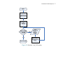
CHAPTER THREE
HARDWARE DESIGN
Automatic Forklift System 12
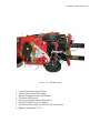
3.1
MECHANICAL DESIGN
The Automatic Forklift System (AFS) utilizes several motors, infrared sensors, and ultrasonic
range finders. The motors are used for the basic operation of the forklift. A DC motor raises
and lowers the forks, while two continuous rotation servo motors drive and steer the forklift in
a tank drive configuration (See Figures 3, 4) and another servo motor tilts the forks. Infrared
sensors are used to detect a white line on a black floor for navigation, as well as detect the
pallet for accuracy when setting a pallet on top of a stack of pallets. There is another IR sensor
pointed to the floor in order to detect the presence of the floor; this is used as the tilt sensor to
detect if the forklift falls over.
Button Sensors
DC Motor
IR Line Sensors
Ball Caster Wheel
Perimeter
Sensor
Tilt Sensor
Servo Motors
IR Sensors
Perimeter Sensor
Top View
Figure 3: Mechanical Top View
The forklift steers by turning off one motor while keeping the other wheel turning (See Figure
4). The caster wheel is there to decrease the forklift’s friction while turning. Even though there
are two wheels in the back, they are raised up and are not used in this project. To go straight
both wheels must be moving in the same direction and at the same speed.
Spinning
Not Moving
Top View
Figure 4: Steering Top View
Automatic Forklift System 13
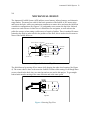
The forks of the AFS have pressure buttons to detect if there is a load on the pallet or not (See
Figures 3, 5,). There is another push button located in the front of the plate where the load will
lean on when the pallet is picked up. This is used to detect when the forks are completely
inserted into the pallet. Ultrasonic range finders detect obstacles in the path of the AFS, they
are shown as perimeter sensors (See Figures 3, 5). Lastly, the wireless Zigbees communicate
between the forklift and the user control to send and receive instructions (See Figure 5).
Perimeter
Sensor
Wireless
Push
Button
IR Sensor Sensors
Perimeter
Sensor
SideView
Figure 5: AFS Sensor Location
The forklift senses the pallet with the IR sensors located in the front of the forks (See figure 6).
The forklift could detect if there is another pallet on top of it by simply moving the forks up
until the correct location is achieved. If there IR sensors detect nothing, then there is not a
pallet on top of it.
Pallet
SideView
Figure 6: Fork Sensor Location 1
Automatic Forklift System 14
The forklift detects the pallet with the push button located on the plate (See Figure 7). When
the forklift lifts the load, the push button on the forks are pushed.
Push
Button
Sensors
IR
Sensor Pallet
SideView
Figure 7: Fork Sensor Location 2
The lines that the forklift follows are ½” wide. Each intersection should consist of a 10” X 10”
square (See Figure 8). The forklift detects the presence of the intersection by way of the side IR
sensors. If the forklift needs to turn at that intersection it will do so at the instant it detects the
first line of the intersection.
10"
Figure 8: Intersection
Automatic Forklift System 15
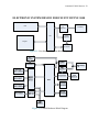
3.2
ELECTRICAL DESIGN
When the operator enters a command, the wireless Zigbee in the user control will send a signal
to the wireless Zigbee in the forklift, which will be inputted into the PIC microcontroller (See
Figures 9 – 11, 13). Depending on the commands, the PIC will drive to the desired location.
Predetermined paths will be laid out with white lines on the floor so the AFS can follow the
lines and decide which path to take depending on the command given. When the perimeter
sensors detect an obstacle in the path of the AFS while it is operating, the PIC stops the
movement of the AFS until the obstacle is removed or the safety is manually overridden, telling
the AFS it is safe to proceed. When the task is completed, the AFS will return to its staging
area to wait for a new command.
With regard to safety, there will be several large pushbuttons that will disable the motors when
pushed and stay that way until the button is pushed again. A LED light located beside the
button will light up to show that this button has been pushed. This emergency shutdown will be
an emergency shut of switch that will physically disconnect power to the motors should all
other safety precautions fail.
An onboard camera will allow the user to see what the forklift sees, so that decisions regarding
troubleshooting or safety can be made more effectively.
LCD
5V
Regulator
PIC
3.3V
Regulator
Keypad
Transceiver
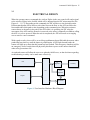
Figure 9: User Interface Hardware Block Diagram
9V battery
Automatic Forklift System 16
Figure 10: Forklift Hardware Block Diagram
Automatic Forklift System 17
Reset
1
Vin
LM7805T Vo
10MΩ
3
1
40
2
39
3
38
4
37
5
36
6
35
7
34
GND
RS
E
9V
R/W
10µF
8
33
9
32
10
31
11
4 MHz
18F452
2
MSB
LSB
30
12
29
13
28
14
27
15
26
16
25
17
24
1
18
23
2
19
22
3
20
21
4
LCD
1KΩ
20
3.3V
19
Rx
18
Tx
17
5
1
Vin
AZ1117T
Vo
3
GND
2
330KΩ
16
XBEE
6
14
8
13
9
10
330KΩ
15
7
12
GND
11
330KΩ
330KΩ
KeyPad
Figure 11: User Interface Hardware Circuit Diagram
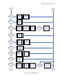
The circuit diagram of the user interface shows the components used and their configuration
(See Figure 11). The LM805T is a 5V regulator used to bring the voltage from the 9V battery
to the needed 5V. This supplies the power to all the components of the receiver. A 10µF
capacitor is used to filter out any ripples left from the 5V regulator.
A 4 MHz Crystal Oscillator with buffer is used for the clock of the PIC18f452.
The wireless Zigbee uses TTL UART communication to interface with the PIC
microcontroller. The wireless Tx pin is connected to the PIC’s Rx pin, and the wireless Rx pin
is connected to the PIC’s Tx pin. It is powered by the 3.3V regulator. This regulator is supplied
by the PIC’s 5V regulator.
The LCD used in this project is a JHD204A series with a display content of 20 character x 4
rows. This LCD has 16 pins; the function for each pin is given below (See Table 6). The last
two pins, 15 and 16, are for background lighting and are not used in this project.
VSS, VCC, VEE: VSS and VCC are connected to ground and +5V, respectively. The LCD has a
1KΩ potentiometer connected to the VEE pin (Pin 3) and +5V for the user to change the
contrast of the LCD.
Automatic Forklift System 18
RS, register select: The register select pin is connected to Pin 3 of the PIC. The LCD contains
two registers, one for the instruction command code and the other is the data register. The RS
pin is used to select the desired register. When RS=0, the command register is selected, which
allows the user to send an LCD command code such as clear display. LCD command codes are
the instructions use to configure the LCD setting (See Table 7). When RS=1, the data register is
selected, which allows the user to send data to be displayed on the LCD.
R/W, read/write: The R/W pin is connected to Pin 5 of the PIC. It allows the user to write or
read information from the LCD. When R/W=1, the user can read from the LCD. When
R/W=0, the user can write data to the LCD to be display.
E, enable: This pin is connected to Pin 4 of the PIC and is used to latch the data sent to the
data pins of the LCD. A high to low pulse, with a minimum of 450 nanosecond pulse width, is
needed to latch the present data at the data pins.
B7-B0, data pins: B7-B0 are the data pins and are connected to Pin 40 – Pin 33 of the PIC,
respectively. These pins may be configured as input or output data pins.
Table 6: Pin Descriptions for LCD
PIN SYMBOL I/0
DESCRIPTION
1
VSS
-Ground
2
VCC
-+5V Power Supply
3
VEE
-Power Supply to Control Contrast
4
RS
I
RS=0 to Select Command Register,
RS=1 to Select Data Register
5
R/W
I
R/W=0 For Write,
R/W=1 For Read
6
E
I/0
Enable
7
B0
I/0
LSB Data
8
B1
I/0
Data Bit
9
B2
I/0
Data Bit
10
B3
I/0
Data Bit
11
B4
I/0
Data Bit
12
B5
I/0
Data Bit
13
B6
I/0
Data Bit
14
B7
I/0
MSB Data
Automatic Forklift System 19
Table 7: LCD Command Codes
Code (Hex) Command to LCD Instruction Register
1
Clear Display Screen
2
Return Home
4
Decrement Cursor (shift cursor to left)
6
Increment Cursor (shift cursor to right)
5
Shift Display Right
7
Shift Display Left
8
Display Off, Cursor Off
A
Display Off, Cursor On
C
Display On, Cursor Off
E
Display On, Cursor On
F
Display On, Cursor Blinking
10
Shift Cursor Position to Left
14
Shift Cursor Position to Right
18
Shift the Entire Display to the Left
1C
Shift the Entire Display to the Right
80
Force Cursor to Beginning of 1st Line
C0
Force Cursor to Beginning of 2nd Line
38
2 Lines and 5x7 Matrix
The input pins to the Keypad are connected to the output pins of the PIC (pins 21 to 24). The
output pins of the Keypad are connected to the input pins of the PIC (pins 15 to 18) through
330 ohm resistors (See Figure 11).
Figure 12: Keypad
Automatic Forklift System 20
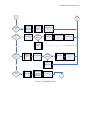
Figure 13: Forklift Hardware Circuit Diagram
Automatic Forklift System 21
There are two power sources in the forklift. One is the 7.2V battery that powers a DC motor
and three servo motors. The other battery is a 9.6V battery that powers two 5V regulators
which in turn supplies power to the PIC, various sensors, and the wireless.
The IR boards are connected to power and ground through one of the 5V regulators. The
outputs of the board are connected to input pins on the PIC. Inside an IR board there is an IR
LED and an IR photo transistor. The IR LED has an 180Ω resistor so the LED is supplied with
the correct current and voltage. The calculation used to get this resistance is Ohm’s Law:
V=I*R
Since we are applying 5V and the LED requires an average voltage 1.4V, we expand the
equation:
(Vs-VL)=I*R
Also, the LED requires an average of 20mA. We get this equation for R:
R= (Vs-VL)/I
R = (5V-1.4V)/.02A = 180Ω
A 10MΩ resistor is connected to one of the inputs of the transistor to dissipate voltage to keep
from getting false readings. The other input of the transistor is connected to a potentiometer so
that the IR can be calibrated to the desired voltage. The output of the comparator has transistors
connected to it, but it needs a resistor on each transistor so one transistor does not take all the
current over other transistor. The output pin of the transistor has a 180Ω resistor connected to
ground to allow the PIC to see logic high and low. The other transistor is used to light an LED
as a visual aid for a high and low so the user can see the status.
The Ultrasonic range finders are powered by the PIC’s 5V regulator. The SDA pin is connected
to pin 15 on the PIC and the SCL pin is connected to pin 16 on the PIC. Both the SDA and SCL
pins require a pull up resistor. The recommended resistance is 1.8KΩ, but we used a 2.2KΩ
resistor since this resistor was available.
The servo controller is connected to the UART pins of the PIC for TTL serial communication.
The servo controller is powered by the 7.2V battery. The outputs are connected to the signal
input of the servos. The servos are connected to the output pins to the servo controller.
Pair of IR LED’s and IR phototransistors are used for sensing distances, and is attached to the
forks for use in detecting pallets. The outputs are connected to pins 2 and 3 for the Analog to
digital converter so the PIC can place a numeric representation of the distance.
Two switches, which are used for detecting a load on the forks, are connected to 5V on one
side. The outputs of the switches are connected to pins 2 and 3 for logic high and low inputs.
There are 330Ω resistors connecting the output to ground to let the PIC see logic levels.
Automatic Forklift System 22
The H-Bridge board contains many transistors. The smaller transistors control the larger
Darlington pair transistors. This is allows to control a large amount of current with a small
signal. When the forward pin is enabled, it enables the PNP transistors to close, allowing the
motor to go forward. When the reverse pins are enabled, it enables the NPN transistors,
allowing the motor to go reverse.
The wireless Zigbee is powered by the 3.3V regulator. It is connected to a virtual UART on the
PIC in the forklift. The PIC does not have 2 UART’s, so in code a UART is programmed into
any desired pins.
For safety reasons there are manual shut off switches in the forklift. This turns off the power
supply to all the motors. It is connected in series with the 7.2V batter. If any of these switches
are pushed, it will turn off the motors. Also when the button is turned off and LED is turned on
to indicate that this button has been pressed.
CHAPTER FOUR
SOFTWARE DESIGN
Automatic Forklift System 23
4.1
USER INTERFACE
Initialization: Figure 14 shows the flowchart of the main program for the user interface. When
the PIC is turned on, the PIC initializes with the proper configurations and Global variables are
declared and initialized. An interrupt function is declared and is called when any data is
received by the RS232 port. The main program then calls the Int_LCD function to configure
the LCD with the desired settings (See Figure 15). Once the function is finished executing, it
returns the pointer back to the main program. Now the LCD is turned on and ready to receive
data from the PIC to be displayed. At this point nothing is display on the LCD.
Screen 1: The Interrupt function is called once the PIC receives a signal from the forklift (See
Figure 16). The user interface then sends a signal back to the forklift to establish a 2-way
wireless communication. Once the 2-way communication has been established, the Interrupt
function calls the Menu function which display two choices to the LCD,“1. Pick up from dock”
and “2. Place on dock.” Once the Menu function is finished executing, it returns the pointer
back to the main program (See Figure 17).
The main program then calls the Check_keys function to check for a key press (See Figure
18.1, 18.2 ). When a key is pressed, the Key_table function is called by the Check_keys
function to take the specified actions associate with that key (See Figure 19.1, 19.2). The
Key_table function is called for all the keys except the arrows, menu, and enter keys. If those
specified keys are pressed, the Arrow function is called to execute their actions (see Figure 20).
Once either key 1 or 2 has been pressed, the Check_keys function will call the Key_table
function. In the Key_table function, the number corresponding to the choice selected is stored
in a variable called Choice for later use in the Transmit function.
Screen 2: The Key_table then calls the Screen function to determine what message to display
next (See Figure 21.1, 21.2). The Screen function calls the Out_LCD_string to display the
string that asks the user to verify the choice he has selected from screen 1 (See Figure 22). The
pointer then returns to the main program and calls the Check_keys function to check for the
user input. The user can either presses 1 to indicate that the choice is correct or 2 to indicate
that the choice is wrong.
If the user presses 2 on the keypad, the Check_keys function will call the Key_table which will
call the Menu function to display the choices given in screen 1. The user is now back at screen
1 waiting for the user to make a selection.
Screen 3: If the user presses 1 on the keypad, the Check_keys function calls the Key_table
which calls the Screen function. The Screen function calls Out_LCD_string to display the
string “Aisle:” This is where the user enters the aisle number he wishes to place or pick up the
pallet.
The pointer returns to the main program to call Check_keys. Once a number has been pressed,
the Key_table will look up the array element corresponding to the key press. If the keypad has
Automatic Forklift System 24
not been pressed more than three times, Key_table will call the Out_LCD function to display
and store the characters pressed. In the Out_LCD function, a variable called counter is
incremented each time a character is display to keep track of the number of keys pressed (See
Figure 23). The character is stored in an array called aisle_number for later use. After the
Out_LCD function displays each character, the pointer returns to the main program to check for
another key press.
The user can also press the “Clear” button to clear all the number(s) entered. When the “Clear”
button is pressed, the Key_table function calls the Clear function to clear the whole LCD and
display the original message in screen 3(See Figure 24).
Once the keypad has been pressed three times, any additional key presses will not be displayed.
To move on to the next step the “enter” key must be pressed.
Screen 4: In this screen, the user is asked to verify his inputs from screen 3. Once the “enter”
key has been pressed in screen 3, the Check_keys function calls the Arrow function to execute
the actions corresponded to the “enter” key. The Arrow function calls the Screen function
which calls the out_LCD_string function to display the characters stored in the array
aisle_number. The pointer returns to the main program to check for any key press.
If the user presses 2, this means that the aisle number entered is wrong. The Key_table function
calls the Screen function to take the user back to screen 3 to re-enter the aisle number.
Screen 5: If the user presses 1, this means that the aisle number entered in screen 3 is the
correct aisle to pull the pallet from or place the pallet to. The Check_keys function will call
Key_table function which will call the Screen function. The Screen function will call the
Transmit function (See Figure 25).
In the Transmit function, if the aisle number and Choice from screen 1 does not match the
preprogram aisle number and choice; the out_LCD_string function will display the message
“Invalid Entry” for a second. The pointer will jump out of the Transmit function and go back to
screen 3. The user will be asked to enter the aisle number again.
If the aisle number and Choice match the preprogrammed aisle number and menu choice, a
value will be stored in the variable selection (See Table 8).
Table 8: Transmission Values
Value to Transmit Menu Choice
0x31
1
0x32
1
0x33
2
0x34
2
Aisle Number
2
3
2
3
The pointer exits from the Transmit function and returns to the Screen function. From there, the
corresponding value is transmitted wirelessly via the wireless modem to the PIC on the forklift.
Automatic Forklift System 25
The Screen function will call the out_LCD_string function to display the message
“Transmitting” to let the user know that the user interface is communicating with the forklift.
If the forklift does not transmit a value back to indicate that it has received the value
transmitted by the user interface, then the LCD will continue displaying “Transmitting.”
Screen 6: Once the forklift receives the value transmitted by the user interface, it will transmit
a confirmation to the user interface. As soon as the user interface receives the confirmation, the
Interrupt function is executed to display the message “Operating” to let the user know that the
forklift is operating. After the Interrupt function is finished executing, the pointer returns to the
main program to check for a key press.
At any given time, the user can press the “Help” button to stop the forklift. The Check_keys
function will call the Key_table which will transmit a value to the forklift to tell the forklift to
stop. The forklift will send back a confirmation to let the user know that the forklift has
stopped. The Interrupt function will be called once the user interface receives the confirmation.
The Interrupt function will call the out_LCD_String to display the message “Stop” and give the
user the choice to resume or go back to the docking area. The pointer returns to the main
program to await the user’s selection from the keypad. Key 1 will resume the process and key 2
will return the forklift to the docking area.
If the user chooses to resume the process, the Check_keys function calls the Key_table which
calls the Screen function to transmit a value to the forklift to tell the forklift to resume the
process. The Screen function will let the user know with an LCD display message that the
forklift is operating.
If the user chooses to go back home, the Check_keys function will call the Key_table function
to execute the appropriate action. If this is the first time the home has been selected then
Key_table will call the Screen function to transmit a value to the forklift to let it know that the
user wants the forklift to go back to the Home aisle. The Screen function will call the
Out_LCD_string function to display the corresponding messages to let the user know that the
forklift is returning home and is operating. The pointer returns back to the main program to
check for key press.
If the forklift detects any object in the way or is tilted over, it will send a signal to the user
interface. The Interrupt function in the user interface will be executed once it receives the
transmitted signal. The user will be asked to resume or go home. The procedure for the choice
selection works the same way as the “Help” button procedure.
Automatic Forklift System 26
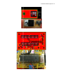
Figure 14: User Interface
Automatic Forklift System 27
Figure 15: Function - Int_LCD
Automatic Forklift System 28
Figure 16: Function - Interrupt
Automatic Forklift System 29
Figure 17: Function - Menu
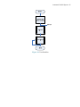
Automatic Forklift System 30
Start
Declare and
Initialize Variables
Send Data
(Row1 Low)
to PortD
Get Input
From
Keypad
Is Any Key
From Row1
Pressed?
Yes
Key_Table:
Look Up Key
Pressed
Yes
Key_Table:
Look Up Key
Pressed
No
Send Data
(Row2 Low)
to PortD
Get Input
From
Keypad
Is Any Key
From Row2
Pressed?
No
Send Data
(Row3 Low)
to PortD
Figure 18.1: Function - Check_Keys
Automatic Forklift System 31
Get Input
From
Keypad
Is Any Key
From Row3
Pressed?
Yes
Key_Table:
Look Up Key
Pressed
Yes
Arrow:
Look Up Key
Pressed
No
Send Data
(Row4 Low)
to PortD
Get Input
From
Keypad
Is Key From
Row4 Pressed?
No
End of Function
Function 18.2: Function - Check_Keys (cont.)
Automatic Forklift System 32
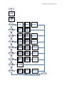
Start
Declare and Initialize
Variable
Array=String Passed
Columns_value=Key
pad Input
Is Column 1
Pressed?
Is On Screen 1?
No
Is On Screen 2?
No
Is On Screen 4?
No
Is On Screen 5?
No
Yes
Yes
Yes
C
Yes
Is #1 On Keypad
Pressed?
Yes
Yes
Choice=1
Screen
No
Is On Screen 1?
No
Is On Screen 2?
No
Is On Screen 4?
No
Is On Screen 5?
No
Yes
Yes
Yes
Yes
Yes
C
No
Is #2 On Keypad
Pressed?
Cursor=2
Menu
Screen_number=2
Keypress=0
Yes
Choice=2
Screen
Screen_number=2
No
No
Screen
Cursor=2
Screen
Figure 19.1: Function - Key_table
Automatic Forklift System 33
Is Column2 Pressed?
Yes
i=1
No
D
Is Column3
Pressed?
Yes
i=2
No
Yes
Is in Screen3?
Clear Display
and Display
User’s Input
Prompt
Yes
Is Clear Key Pressed?
No
No
Is “0” Key Pressed?
Is in Screen3 & Key
Pressed Less Than 3
Times?
Yes
Out_LCD:
Display ‘0’
Yes
No
No
“Help” Button
Pressed?
Yes
Screen_number=5
Yes
Tx ‘5’
No
No
Key=array[i]
D
No
Is in Screen3 & Key
Pressed Less Than 3
Times?
Yes
Out_LCD:
Display
Character
No
i=0
End of Function
Figure 19.2: Function – Key_table (cont.)
Automatic Forklift System 34
Figure 20: Function – Arrow
Automatic Forklift System 35
Start
Clear
Is Cursor=1?
Yes
Is On Screen 1
(Menu)?
No
Is On Screen 2
(Verify Choice)?
No
Is On Screen 3
(User Input)?
No
Is On Screen 4
(Verify Input)?
Yes
Yes
Yes
Yes
Yes
Status=1
No
Out_LCD_string
Verify Choice1
Out_LCD_ string
Ask For User Input
Out_LCD_string
Verify User Input
Screen=5
Transmit
No
Screen=3
Screen=4
Out_LCD_string
Display
Transmitting
Screen
Screen=2
Cursor=1
No
End of Function
Is Cursor=2?
Yes
Figure 21.1: Function – Screen
Tx Value
Corresponding to
Choice and Aisle
Number
No
Automatic Forklift System 36
Yes
Is On Screen 1
(Menu)?
Yes
No
Is On Screen 2
?
Out_LCD_string
Verify Choice2
No
Is On Screen 5
(Operating)?
Yes
No
Tx ‘2’
Yes
Tx ‘7’
Indicate=1
Yes
Out_LCD_string
Return Home
Out_LCD_string
Operate Home
Out_LCD_string
Operate Home
Screen_number=5
Keypress=1
Indicate=1
Figure 21.2: Function – Screen (cont.)
No
Out_LCD_string
Operating
Automatic Forklift System 37
Figure 22: Function - Out_LCD_string
Automatic Forklift System 38
Figure 23: Function – Out_LCD
Automatic Forklift System 39
Start
Send Value
to Clear E,
R/W, RS
Send
Command
to PortB to
Clear
Display
Is “Clear” Key
Pressed?
No
Yes
Display
User’s
Prompt
Counter=0
End of Function
Figure 24: Function - Clear
Automatic Forklift System 40
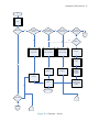
Start
aisle_number [0]
= ‘0’
Yes
aisle_number [1]
= ‘0’
Yes
aisle_number [2]
= ‘2’ & choice = 1
No
No
Display
Invalid Entry
String
aisle_number [2]
= ‘3’ & choice = 1
Yes
Selection = 0x31,
Status = 0
Yes
Selection = 0x32,
Status = 0
Yes
Selection = 0x33,
Status = 0
Yes
Selection = 0x34,
Status = 0
No
Status=1
Selection=0
aisle_number [2]
= ‘2’ & choice = 2
No
aisle_number [2]
= ‘3’ & choice = 2
No
Cursor=1
End of Function
Figure 25: Function – Transmit
Automatic Forklift System 41
4.2
FORKLIFT
Figure 26.1 to 26.4 shows the flowchart of the main program for the forklift. When the PIC is
turned on, the PIC initializes with the proper configurations. Global variables are declared and
initialized, and an interrupt function is declared for any data received by the RS232 port. The
main program transmits a value to the user interface to see if the user interface is turned on.
The main program will wait until the user interface has sent back a confirmation character
before executing the rest of the main program. Once a 2-way communication has been
established between the forklift and user interface, the main program calls the range_finderf
function to check for object in front of the forklift. If there is no object, the Tilt_Check function
is called to check if the forklift has been tilted over (See Figure 27). If the forklift has not been
tilted over, the Lower_Fork function is called to lower the forks to its lowest position (See
Figure 28). The Lift_Fork function is called next to lift the forks up 1.5 inches from the ground
(See Figure 29). Finally, the Set_Neutral function is called to tilt the forks parallel to the
ground (See Figure 30). Once the forklift has initialized the position of the forks, it is ready to
receive instruction from the user interface.
When the forklift receives a value from the user interface at its RS232 port, the Interrupt
function is called to take in the data. The pointer jumps out of the Interrupt function back to the
main program and compares the value received to several preprogrammed instructions. If there
is a match corresponding to the value sent, then the instructions corresponding to the value will
be executed. Once the instructions are finished, then it will wait for the next command from the
user interface. For details see code in Appendix B.
Automatic Forklift System 42
Figure 26.1: Forklift
Automatic Forklift System 43
Figure 26.2: Forklift (cont.)
Automatic Forklift System 44
B
E
Is number = 7?
Yes
Check for
object in way
of forklift
Yes
Turn right
using values
0x01 and
0x08
Yes
Check for
object in way
of forklift
Go straight
on line
No
Is number = 8?
No
Is number = 9?
Check for the no
pallet line
Go straight
on line
If no pallet
Yes
Increment number
by 1
No
Is number =
10?
Yes
Place pallet,
reverse out,
turn around,
and
increment
number by 1
Yes
Check for
object in way
of forklift
No
Is number =
11?
Go straight
on line
No
Is number =
12?
Yes
Turn left using
values 0x00 &
0x74, and
increment
number
No
Is number =
13?
Yes
Check for
object in way
of forklift
Go straight
on line
No
Is number =
14?
Yes
Turn left using
values 0x00 &
0x74, and
increment
number
No
Is number =
15?
No
Yes
Check for
object in way
of forklift
Go straight
on line
Check for left line
Is left line
present?
Yes Increment number
No
C
D
Figure 26.3: Forklift (cont.)
Automatic Forklift System 45
C
D
Is number =
16?
Yes
Check for
object in way
of forklift
Turn forklift
around by
1800
Yes
Check for right line
Is right line
present?
Increment number
by 1
No
Is number =
17?
Yes
Increment number
by 1
Stop forklift
Set status to 0
No
Go straight
on line
No
Is number =
18?
Check for
object in the
back
Check for left line
Yes
Stop forklift
Reverse
forklift on line
No
Is number =
19?
Is left line
present?
Stop forklift
Let user know
forklift is ready
for next
instruction by
sending ‘D’
Choice=0
Figure 26.4: Forklift (cont.)
F
Increment number
by 1
Automatic Forklift System 46
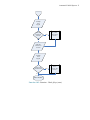
Start
Read PIN_C4 to
check if forklift is
tilted over
Is PIN_C4=0?
Yes
Stop forklift
Status=0
No
Let user know
forklift is tilted over
by sending ‘4’
No
Received
confirmation from
user interface?
Yes
End of function
Figure 27: Function - Tilt_Check
Automatic Forklift System 47
Start
Initialize variables
Read and store
the status of forks
by reading the
switch on bottom
of fork
Is forks at its
lowest position?
No
Lower down the
forks
Yes
Stop lowering
down forks
End of function
Figure 28: Function - Lower_Fork
Automatic Forklift System 48
Figure 29: Function - Lift_Fork
Automatic Forklift System 49
Figure 30: Function - Set_Neutral
CHAPTER FIVE
SERVICE MANUAL
Automatic Forklift System 50
Service Manual
JNM Technologies
Fluffy Bunny-3000 Series
Automatic Forklift
5/29/2008
Automatic Forklift System 51
TABLE OF CONTENTS
Hazards ........................................................................................................................................52
Operating Instructions .................................................................................................................53
Electronic System Design for Fluffy Bunny-3000 ......................................................................54
Overall Mechanical Components Layout ....................................................................................57
Intersection Layout ......................................................................................................................60
Overall Electronic Components Layout ......................................................................................61
Troubleshooting ...........................................................................................................................68
Automatic
tic Forklift
Fo
System 52
HAZARDS
DANGER
Death or serious
rious injury may occur.
Stay clear off mov
moving forklift.
Do not service
ice un
unless forklift is turned off and disabled.
abled.
Do not ride forkli
forklift.
CAUTION
Property Damage
amage may occur.
Do not overload
load fforklift.
Do not carryy a loa
load downhill.
Automatic Forklift System 53
OPERATING INSTRUCTIONS
Please read the entire manual before using product.
In order to operate the Automatic Forklift System the navigation lines must be mapped on the
floor properly, and the forklift programmed to you specific application. Please contact JNM
Technologies for assistance.
Set Up and Turning On:
Place forklift in the Home aisle with both the front IR sensors above the navigation line.
*Important* Turn on the user interface FIRST. After turning on the user interface, turn on the
power to the motors of the forklift via the switch on the underside of the forklift. Then turn on
the power to the sensors and PIC of the forklift via the switch on the side.
Operation:
When the first turned on you will see screen 1 which gives you two choices, “1. Pick up from
Docks” and “2. Place to Docks.” Make your choice by pressing the corresponding number on
the key pad, or by using the up and down arrows to highlight your choice then press enter.
The screen will now ask you to confirm your choice. Choose “1. Yes” to confirm and continue
to the next screen. Choose “2. No” to return to the previous screen if you made the wrong
choice initially.
If you chose “1. Yes” the screen will now ask you to enter the aisle number you wish to bring
the pallet to or take the pallet from. When you are done, press Enter. The screen will again ask
you to confirm you decision. Choose “2. No” if you entered the wrong aisle number and the
screen will ask you to enter the aisle number again.
Choose “1. Yes” to transmit the instructions to the forklift so it can carry out the desired
process. While the forklift is operating the screen will display “Operating” until the forklift is
done and has returned home, at which time, the first screen will reappear.
At any time during operation, you may hit the “Help” button to stop the forklift. The screen
will allow you to choose to continue or to return home. If you wish for the forklift to continue
doing what it was doing, choose “1. Continue”. Choose “2. Home” if you want the forklift to
abort it’s current operation and return home.
If at anytime during operation an object or person gets in the way, or the forklift tips over, the
forklift will stop and the screen will give you the option to continue or go home. Before
choosing “1. Continue” check the live video feed to ensure that the forklift has been up-righted
and/or the object has been removed from its path.
Automatic Forklift System 54
ELECTRONIC SYSTEM DESIGN FOR FLUFFY BUNNY-3000
LCD
5V
Regulator
PIC
3.3V
Regulator
Keypad
Transceiver
Figure 31: User Interface Hardware Block Diagram
Figure 32: Forklift Hardware Block Diagram
9V battery
Automatic Forklift System 55
Figure 33: User Interface Hardware Circuit Diagram
Automatic Forklift System 56
IR Sensor Board
180Ω
+5V
GND
10KΩ
180Ω
180Ω
10KΩ
+
_
10MΩ
5KΩ
10MΩ
1
Reset
BP2
Vin
2
PB1
330Ω
LM7805T Vo
3
GND
9.6V
3
LM7805T Vo
330Ω
Vin
Vout
GND
10MΩ
1
330Ω
180Ω
10MΩ
2
10µF
1
40
2
39
3
38
4
37
5
36
6
35
7
34
8
33
9
32
10
31
11
5V
Vout
IR Sensor Board
Gnd
5V
Vout
IR Sensor Board
Gnd
30
12
29
13
28
5V
Vout
IR Sensor Board
Gnd
4 MHz
14
27
15
26
16
25
17
24
18
23
19
22
20
21
5V
Vout
IR Sensor Board
Gnd
5V
Vout
IR Sensor Board
Gnd
5V
Vout
IR Sensor Board
Gnd
5V
Vout
1
IR Sensor Board
Gnd
20
3.3V
2
3
19
Rx
18
Tx
4
3
LM1086CTVo
Vin
2
5V
Vout
15
7
14
8
13
9
10
Gnd
16
XBEE
6
GND
IR Sensor Board
17
5
1
5V
Vout
IR Sensor Board
Gnd
12
11
GND
2.2K
2.2K
Gnd
Vcc
Signal
Servo Continuous
jumper
Servo 0
jumper
reset
Serial Out
Serial In
Servo 1
Servo
Control
Gnd
Vcc
Signal
Ultrasonic Range
Finder
Servo 2
Servo 3
Gnd
Vcc
Vin
Servo 4
Gnd
Servo 5
Signal
GND Mode SCL SCA Vcc
GND Mode SCL SCA Vcc
Servo
Servo
Ultrasonic Range
Finder
Continuous
Servo 6
Servo 7
Vin Forward
7.2V
H-Bridge
Vin Reverse
Gnd
ES3
+7.2V
ES2
7.2V
ES1
2.2KΩ
2.2KΩ
330
2.2KΩ
10KΩ
2.2KΩ
330
10KΩ
100nF
Vin Forward
22KΩ
22KΩ
10KΩ
22KΩ
10KΩ
22KΩ
Vin Reverse
Gnd
Figure 34: Forklift Hardware Circuit Diagram
330
Automatic Forklift System 57
OVERALL MECHANICAL COMPONENTS LAYOUT
8
1
2
6
4
8
5
7
Figure 35.1: Forklift
1.
2.
3.
4.
5.
6.
7.
8.
9.
Front Proximity Sensor (Sonic Ranger)
Rear Proximity Sensor (Sonic Ranger)
Pallet Sensors (IR Sensors)
Load Sensors (Buttons)
Pallet Sensor (Push Button)
Antenna (Wireless Zigbee)
Limit Switch
Emergency Manual Shut Off (Both Sides and Back)
Video Camera
3
Automatic Forklift System 58
2
4
5
1
8
6
3
7
Figure 35.2: Forklift (cont.)
1.
2.
3.
4.
5.
6.
7.
8.
Continuous Rotation Servo Motors
Intersection Detectors (IR Sensors)
Reverse Navigation Sensors (IR Sensors)
Tilt Sensor (IR Sensors)
Forward Navigation Sensors (IR Sensors)
On-Off Switch (For Power to Motors)
On-Off Switch (On Side; For Power to PIC and Sensors)
Battery Compartment (7.2V)
Automatic Forklift System 59
2
1
3
4
5
Figure 36: User Interface
1.
2.
3.
4.
5.
On-Off Switch (On Side)
Antenna (Wireless Zigbee)
LCD
Keypad
Battery Compartment (9V; On Back)
Automatic Forklift System 60
INTERSECTION LAYOUT
The lines that the forklift follows are ½” wide. Each intersection should consist of a 10” X 10”
square (See Figure 36). The forklift detects the presence of the intersection by way of the side
IR sensors. If the forklift needs to turn at that intersection it will do so at the instant it detects
the first line of the intersection.
10"
Figure 37: Intersection
Automatic Forklift System 61
OVERALL ELECTRONIC COMPONENTS LAYOUT
Figure 38: H-Bridge
Automatic Forklift System 62
Figure 39: IR Boards
Automatic Forklift System 63
Figure 40: Ultrasonic Board I2C connection to PIC
Automatic Forklift System 64
Figure 41: Keypad
Automatic Forklift System 65
Figure 42: IR Comparator Board
Automatic
tic Forklift
Fo
System 66
Figure 43: 5V Regulator
Figure
igure 44: 18F452 PIC Microcontroller board
Automatic Forklift System 67
Figure 45: Wireless Zigbee
Automatic Forklift System 68
TROUBLESHOOTING
Table 9: Troubleshooting
No
1
2
3
4
Problem
Possible
Cause
Repair
Solution
Observations
Place a white mat under the IR sensors. Adjust the potentiometer
on the comparator board until the
LED is turned on.
Then replace the mat with a
black mat and see if the LED is
off. If not then adjust the
potentiometer until it turns off.
Replace Transistor
+5VDC when IR comparator
IR navigation sensor does 3906 Transistor is
board when white mat is under
not give a signal out, but defective.
the IR sensors. 0V DC when
LED on comparator board
is working
black mat is under the IR
sensors.
A blinking green light on the
Servos not steering or
Servo controller not
Check the input to and output
servo controller indicates that
tilting forks
receiving or not
from servo controller to
transmitting data
determine if the problem lies in the controller is working
the PIC, controller, or the servos properly. A red light indicates
that the controller isn’t
themselves. Try restarting the
receiving the proper data.
forklift.
Forklift starts turning in IR line sensor is
• Turn on sensors, but not main
circles
damages or comparator
power to the motor. Place a
for the IR sensor is not
white mat under the sensors.
working
Check to see voltage on the
output of the sensor. If the
voltage is between 3-5 V, this
is good. If lower voltage is
shown, then sensor is broken.
Replace sensor.
• Place a black mat under the
sensor. Check the voltage; if it
is above 3V, then the senor is
broken. Replace sensors.
• If voltages for the sensor are
correct, check # 2 for repairs
on comparator board.
IR navigation sensors not Potentiometer is not
working properly
calibrated properly
5
Tilt sensor is not working 1. IR sensor is damaged. 1. Check # 4.
2. IR sensor comparator 2. Check # 4.
board is not working. 3. Bend the sensors to the proper
direction toward the floor
3. IR sensor is
positioned incorrectly 4. Turn the potentiometer on the
comparator board until the
4. IR sensor is not
LED light turns on.
calibrated.
6
1. Button is
Pallet sensor is not
disconnected.
working properly or
2. Button is damaged
doesn’t recognize the
pallet is all the way in the 3. Wire has a short.
1. Check to see if the button is
connected to the
microcontroller.
2. Test the button. If damaged
2. Make sure the power to the
motors is off. Turn on the
power to the microcontroller.
Check the voltage input of the
Automatic Forklift System 69
forks.
4. Button is position
improperly
replace button
fork button. If 5V then power
3. Test the continuity of the
is working correctly. If not
then the input is damaged.
wires. If there is a short.
Check the output of the button.
Replace the wire
4. Run the forklift with a dummy 0V should be present when the
button is not pressed. 5V
pallet of a typical load. If it
should be present when the
still does not stop, then the
button needs to be moved.
button is pressed.
Check again until it detects the
pallet.
REFERENCES
REFERENCES
Big Joe California North, Inc. Products. Retrieved October 3, 2007, from
http://www.bigjoelift.com/html/products/elecsitdown.html
Digi-Key.com. (2007). Retrieved October 2, 2007, from
http://us.digikey.com/scripts/DkSearch/dksus.dll?Detail?name=CH396-ND
FMCTechnologies. (2005). Retrieved September 6, 2007, from http://www.fmcsgvs.com.
Jameco Electronics. (2007). Retrieved September 8, 2007, from
http://www.jameco.com/webapp/wcs/stores/servlet/StoreCatalogDisplay?storeId=10001
&catalogId=10001&langId=-1.
Savant automation. (2007). Retrieved September 6, 2007, from http://www.agvsystems.com/.
SparkFun Electronics. (2005). Retrieved September 7, 2007, from
http://www.sparkfun.com/commerce/categories.php.
TRANSBOTICS. (2007, September 21). Retrieved September 6, 2007, from
http://www.transbotics.com/.
U.S. Department of Labor Bureau of Labor Statistics. (2007, October 4). Occupational Outlook
Handbook. Retrieved September 7, 2007, from http://www.bls.gov/oco/.
WWW.ALLDATASHEET.COM. (2007). Retrieved September 8, 2007, from
http://www.alldatasheet.com.
APPENDIX A
ID
Task Name
1
Senior Project
2
Duration
Semester 1
3
Senior Project Formation
4
Senior Project Initial Proposal
5
Project Ideas
6
Idea 1: Blimp Camera
7
Idea 2: Security System
8
Idea 2: Forklift System
Start
Finish
Predecessors
Resource Names
219 days
Wed 7/18/07
Thu 5/8/08
65 days
Wed 7/18/07
Wed 10/17/07
11 days
Wed 7/18/07
Wed 8/1/07
7 days
Mon 8/6/07
Wed 8/15/07
3 days
Mon 8/6/07
Wed 8/8/07 3
1 day
Mon 8/6/07
Mon 8/6/07 3
Mai
Josh,Mai,Nick
2 days
Mon 8/6/07
Tue 8/7/07 3
Nick
1 day
Wed 8/8/07
Wed 8/8/07 3
Josh
9
Description
4 days
Thu 8/9/07
Tue 8/14/07 8
Mai
10
Hardware Diagram
3 days
Fri 8/10/07
Tue 8/14/07 8
Nick
11
Software Flow Chart
4 days
Thu 8/9/07
Tue 8/14/07 8
Josh
12
Initial Proposal Sent In
0 days
Wed 8/15/07
Wed 8/15/07 10,11,9,13
13
Meeting With English Advisor
1 day
Mon 8/13/07
Mon 8/13/07
14
Project Acceptance
0 days
Wed 8/22/07
Wed 8/22/07
15
Progress Report # 1
Mai,Nick,Josh
6 days
Thu 8/23/07
16
Scope
4 days
Fri 8/24/07
Wed 8/29/07 14
Fri 8/31/07
Mai
17
Future Enhancements
4 days
Fri 8/24/07
Wed 8/29/07 14
Josh
18
Target Audience
5 days
Thu 8/23/07
Wed 8/29/07 14
Nick
19
Progress Report Submitted
0 days
Fri 8/31/07
20
Meeting With English Advisor Online
1 day
Wed 8/29/07
Wed 8/29/07
21
Progress Report # 2
Fri 8/31/07 16,17,18,20
Mai,Josh,Nick
6 days
Wed 9/5/07
Wed 9/12/07
22
Budget
6 days
Wed 9/5/07
Wed 9/12/07 19
Mai
23
Market Analysis
6 days
Wed 9/5/07
Wed 9/12/07 19
Nick,Josh
24
Gantt Chart
4 days
Fri 9/7/07
Wed 9/12/07 19
Josh
25
Progress Report Sent In
0 days
Wed 9/12/07
Wed 9/12/07 22,23,24,26
26
Meeting with English Advisor
1 day
Mon 9/10/07
Mon 9/10/07
Josh,Mai,Nick
27
Email English Advisor Rough Draft Report # 2
1 day
Tue 9/11/07
Tue 9/11/07
Josh,Mai,Nick
28
Progress Report #3
5 days
Wed 9/19/07
Tue 9/25/07
29
Hardware
5 days
Wed 9/19/07
Tue 9/25/07
30
Diagrams
4 days
Wed 9/19/07
Mon 9/24/07 25
Josh
31
Hardware Write-Up
3 days
Fri 9/21/07
Tue 9/25/07 25
Nick
32
5 days
Wed 9/19/07
Tue 9/25/07
Diagrams
4 days
Wed 9/19/07
Mon 9/24/07 25
Josh
34
Software Write-Up
3 days
Fri 9/21/07
Tue 9/25/07 25
Mai
35
Progress Report # 3 Sent In
0 days
Wed 9/26/07
Wed 9/26/07 34,30,31,33
36
Rough Draft Of Written Report
3 days
Mon 10/1/07
Wed 10/3/07
33
Software
Page 1
Josh,Mai,Nick
ID
Task Name
Duration
Start
Finish
Predecessors
Resource Names
37
Formatting
2 days
Mon 10/1/07
Tue 10/2/07 35
38
Grammar
2 days
Tue 10/2/07
Wed 10/3/07 35
Mai,Nick
39
Diagrams
2 days
Tue 10/2/07
Wed 10/3/07 35
Josh
40
Compilation
2 days
Tue 10/2/07
Wed 10/3/07 35
Josh,Mai,Nick
41
Risks And Contingencies
2 days
Tue 10/2/07
Wed 10/3/07 35
Josh,Mai
42
Safety
1 day
Tue 10/2/07
Tue 10/2/07 35
Mai
43
Appendix
2 days
Tue 10/2/07
Wed 10/3/07 35
Nick
44
Update Gantt Chart
1 day
Tue 10/2/07
Tue 10/2/07 35
Josh
45
46
Rough Draft Turned In
Power Point
0 days
Wed 10/3/07
5 days
Thu 10/4/07
Wed 10/3/07 37,38,39,40,41,42,43,44
Mai
Josh,Mai,Nick
Wed 10/10/07
47
Create Cells
3 days
Thu 10/4/07
Mon 10/8/07 45
Mai,Nick
48
Work On Animation
3 days
Fri 10/5/07
Tue 10/9/07 45
Josh
Editing
4 days
Fri 10/5/07
Wed 10/10/07 45
Josh,Mai,Nick
1 day
Mon 10/8/07
Mon 10/8/07 45
Josh,Mai,Nick
49
50
Meeting With English Adivsor
51
Final Draft of Written Report
3 days
Mon 10/8/07
52
Formatting
2 days
Mon 10/8/07
Tue 10/9/07 45
53
Gantt Chart
2 days
Tue 10/9/07
Wed 10/10/07 45
Josh
54
Hardware
2 days
Tue 10/9/07
Wed 10/10/07 45
Nick
55
Software
2 days
Tue 10/9/07
Wed 10/10/07 45
Mai
56
Formatting
1 day
Wed 10/10/07
Wed 10/10/07 45
Josh,Mai,Nick
0 days
Wed 10/10/07
Wed 10/10/07 52,53,54,55,56
Josh,Mai,Nick
0 days
Wed 10/17/07
Wed 10/17/07 57
Josh,Mai,Nick
57
58
59
Report Sent In
Final Presentation
Semester 2
83 days
Sat 11/3/07
1 day
Mon 11/5/07
Wed 10/10/07
Josh,Mai
Wed 2/20/08
60
Purchased Forklift
Mon 11/5/07 58
Josh
61
Completed H-Bridges
62
Received Forklift
Josh,Nick
63
Tested Hall-Effect Sensors
1 day
Wed 11/7/07
64
Progress Report #1
0 days
Wed 11/28/07
65
Program for Servo Motor Completed
4 days
Wed 11/28/07
66
Forklift Started Running
1 day
Tue 12/4/07
67
New Navigation Planned
24 days
Wed 11/7/07
68
Meet English Advisor
1 day
Fri 12/7/07
69
Progress Report # 2
0 days
Wed 12/12/07
Wed 12/12/07 64,68
Mai,Nick
70
Forklift follows straight line
3 days
Fri 12/14/07
Tue 12/18/07 67,66
Josh,Mai
71
IR boards built and installed
9 days
Mon 1/7/08
72
Meet English Advisor
1 day
Tue 1/15/08
2 days
Sat 11/3/07
Mon 11/5/07 58
1 day
Mon 11/12/07
Mon 11/12/07 60
Page 2
Wed 11/7/07
Wed 11/28/07 62,63
Josh,Mai,Nick
Josh
Nick
Sat 12/1/07 64
Josh,Mai
Tue 12/4/07 63,65
Josh,Mai
Wed 12/5/07 58
Fri 12/7/07 64
Nick,Josh
Nick,Josh,Mai
Thu 1/17/08 70
Josh,Nick
Tue 1/15/08
Mai,Josh,Nick
ID
Task Name
Duration
Start
Finish
Predecessors
Resource Names
73
Progress Report #3
0 days
Wed 1/16/08
Wed 1/16/08 72
74
Wireless and Rangers working separately
3 days
Thu 1/17/08
Sat 1/19/08 73
Josh,Mai
75
Wireless Modem not working in Project
2 days
Fri 1/25/08
Sat 1/26/08 74
Josh,Mai
76
Both Rangers working on same bus
1 day
Mon 1/28/08
Mon 1/28/08 69
Mai,Josh
77
Mode changed in servo control and Forklift follow line
3 days
Tue 1/29/08
Thu 1/31/08 70
Josh,Mai
78
Tilt sensor is installed and working
4 days
Wed 1/30/08
Mon 2/4/08 70
Nick,Josh,Mai
79
Tilt sensor + straight track + range finder working
3 days
Mon 2/4/08
Wed 2/6/08 76,77
Nick,Josh,Mai
80
Rough Draft
6 days
Wed 1/30/08
Wed 2/6/08 73
Nick,Josh,Mai
81
Final Draft
0 days
Wed 2/13/08
Wed 2/13/08
82
Presentation
0 days
Wed 2/20/08
Wed 2/20/08
50 days
Mon 3/3/08
Thu 5/8/08
10 days
Mon 3/3/08
Fri 3/14/08
83
Semester 3
84
Zigbee wireless working
85
Progress Report #1
0 days
Thu 3/27/08
Thu 3/27/08
86
Steering Algorithm
16 days
Fri 3/14/08
Sun 4/6/08
87
Rebuilt Steering
2 days
Mon 4/7/08
Tue 4/8/08 86
88
Forward straight line navigation finalized
5 days
Mon 4/7/08
Fri 4/11/08
89
Reconfigured navigation IR sensors
1 day
Fri 4/11/08
Fri 4/11/08
90
Turning algorithm + intersection layout finalized
1 day
Mon 4/14/08
Mon 4/14/08
91
Progress Report #2
0 days
Thu 4/17/08
Thu 4/17/08
92
Midterm Prototype Preview
0 days
Thu 4/24/08
Thu 4/24/08
93
Forklift locates pallet, picks it up, and reverses out
2 days
Fri 4/25/08
Sat 4/26/08
94
Progress Report #3
0 days
Thu 5/1/08
Thu 5/1/08
95
All programs are integrated and hardware finished
4 days
Mon 5/5/08
Thu 5/8/08
Page 3
Nick,Mai,Josh
ID
5, '07
M T
W
T
F
S
Jul 22, '07
S M T
W
T
F
S
Jul 29, '07
S M T
W
T
F
S
Aug 5, '07
S M T
W
T
F
S
Aug 12, '07
S M T
W
T
F
S
Aug 19, '07
S M T
W
T
F
1
2
3
Josh,Mai,Nick
4
5
6
Mai
7
Nick
8
Josh
9
Mai
10
Nick
11
Josh
12
8/15
13
Mai,Nick,Josh
14
8/22
15
16
17
18
19
20
21
22
23
24
25
26
27
28
29
30
31
32
Project: 5-8-08
Date: Thu 5/29/08
Task
Milestone
External Tasks
Split
Summary
External Milestone
Progress
Project Summary
Deadline
Page 1
ID
5, '07
M T
W
T
F
S
Jul 22, '07
S M T
W
T
F
S
Jul 29, '07
S M T
W
T
F
S
Aug 5, '07
S M T
W
T
F
S
Aug 12, '07
S M T
33
34
35
36
37
38
39
40
41
42
43
44
45
46
47
48
49
50
51
52
53
54
55
56
57
58
59
60
61
62
63
64
Project: 5-8-08
Date: Thu 5/29/08
Task
Milestone
External Tasks
Split
Summary
External Milestone
Progress
Project Summary
Deadline
Page 2
W
T
F
S
Aug 19, '07
S M T
W
T
F
ID
5, '07
M T
W
T
F
S
Jul 22, '07
S M T
W
T
F
S
Jul 29, '07
S M T
W
T
F
S
Aug 5, '07
S M T
W
T
F
S
Aug 12, '07
S M T
65
66
67
68
69
70
71
72
73
74
75
76
77
78
79
80
81
82
83
84
85
86
87
88
89
90
91
92
93
94
95
Project: 5-8-08
Date: Thu 5/29/08
Task
Milestone
External Tasks
Split
Summary
External Milestone
Progress
Project Summary
Deadline
Page 3
W
T
F
S
Aug 19, '07
S M T
W
T
F
S
Aug 26, '07
S M T
W
T
F
S
Sep 2, '07
S M T
W
T
F
S
Sep 9, '07
S M T
W
T
F
S
Sep 16, '07
S M T
W
T
F
S
Sep 23, '07
S M T
W
Mai
Josh
Nick
8/31
Mai
Nick,Josh
Josh
9/12
Josh,Mai,Nick
Josh,Mai,Nick
Josh
Nick
Project: 5-8-08
Date: Thu 5/29/08
Task
Milestone
External Tasks
Split
Summary
External Milestone
Progress
Project Summary
Deadline
Page 4
T
F
S
Sep 30, '07
S M T
W
T
F
S
Oct
S
S
Aug 26, '07
S M T
W
T
F
S
Sep 2, '07
S M T
W
T
F
S
Sep 9, '07
S M T
W
T
F
S
Sep 16, '07
S M T
W
T
F
S
Sep 23, '07
S M T W
Josh
T
F
S
Sep 30, '07
S M T
W
T
F
S
Oct
S
Mai
9/26
Mai
Mai,Nick
Josh
Josh,Mai,Nick
Josh,Mai
Mai
Nick
Josh
10/3
Project: 5-8-08
Date: Thu 5/29/08
Task
Milestone
External Tasks
Split
Summary
External Milestone
Progress
Project Summary
Deadline
Page 5
S
Aug 26, '07
S M T
Project: 5-8-08
Date: Thu 5/29/08
W
T
F
S
Sep 2, '07
S M T
W
T
F
S
Sep 9, '07
S M T
W
T
F
S
Sep 16, '07
S M T
W
T
F
S
Sep 23, '07
S M T
W
Task
Milestone
External Tasks
Split
Summary
External Milestone
Progress
Project Summary
Deadline
Page 6
T
F
S
Sep 30, '07
S M T
W
T
F
S
Oct
S
7, '07
M T
W
T
Project: 5-8-08
Date: Thu 5/29/08
F
S
Oct 14, '07
S M T
W
T
F
S
Oct 21, '07
S M T
W
T
F
S
Oct 28, '07
S M T
W
T
F
S
Nov 4, '07
S M T
W
T
F
Task
Milestone
External Tasks
Split
Summary
External Milestone
Progress
Project Summary
Deadline
Page 7
S
Nov 11, '07
S M T
W
T
F
S
Nov 18, '07
S M T
7, '07
M T
W
T
F
S
Oct 14, '07
S M T
W
T
F
S
Oct 21, '07
S M T
W
T
F
S
Oct 28, '07
S M T
W
T
F
S
Nov 4, '07
S M T
W
T
F
S
Nov 11, '07
S M T
W
T
F
Mai,Nick
Josh
Josh,Mai,Nick
Josh,Mai,Nick
Josh,Mai
Josh
Nick
Mai
Josh,Mai,Nick
10/10
10/17
Josh
Josh,Nick
Josh,Mai,Nick
Josh
Project: 5-8-08
Date: Thu 5/29/08
Task
Milestone
External Tasks
Split
Summary
External Milestone
Progress
Project Summary
Deadline
Page 8
S
Nov 18, '07
S M T
7, '07
M T
W
T
Project: 5-8-08
Date: Thu 5/29/08
F
S
Oct 14, '07
S M T
W
T
F
S
Oct 21, '07
S M T
W
T
F
S
Oct 28, '07
S M T
W
T
F
S
Nov 4, '07
S M T
W
T
F
Task
Milestone
External Tasks
Split
Summary
External Milestone
Progress
Project Summary
Deadline
Page 9
S
Nov 11, '07
S M T
W
T
F
S
Nov 18, '07
S M T
W
T
F
S
Nov 25, '07
S M T
Project: 5-8-08
Date: Thu 5/29/08
W
T
F
S
Dec 2, '07
S M T
W
T
F
S
Dec 9, '07
S M T
W
T
F
S
Dec 16, '07
S M T
W
T
F
S
Dec 23, '07
S M T
Task
Milestone
External Tasks
Split
Summary
External Milestone
Progress
Project Summary
Deadline
Page 10
W
T
F
S
Dec 30, '07
S M T
W
T
W
T
F
S
Nov 25, '07
S M T
W
T
F
S
Dec 2, '07
S M T
W
T
F
S
Dec 9, '07
S M T
W
T
F
S
Dec 16, '07
S M T
W
T
F
S
Dec 23, '07
S M T
11/28
Project: 5-8-08
Date: Thu 5/29/08
Task
Milestone
External Tasks
Split
Summary
External Milestone
Progress
Project Summary
Deadline
Page 11
W
T
F
S
Dec 30, '07
S M T
W
T
W
T
F
S
Nov 25, '07
S M T
W
T
F
S
Dec 2, '07
S M T
Josh,Mai
W
T
F
S
Dec 9, '07
S M T
W
T
F
S
Dec 16, '07
S M T
W
T
F
S
Dec 23, '07
S M T
Josh,Mai
Nick,Josh
Nick,Josh,Mai
12/12
Josh,Mai
Project: 5-8-08
Date: Thu 5/29/08
Task
Milestone
External Tasks
Split
Summary
External Milestone
Progress
Project Summary
Deadline
Page 12
W
T
F
S
Dec 30, '07
S M T
W
T
F
S
Jan 6, '08
S M T
Project: 5-8-08
Date: Thu 5/29/08
W
T
F
S
Jan 13, '08
S M T
W
T
F
S
Jan 20, '08
S M T
W
T
F
S
Jan 27, '08
S M T
W
T
F
S
Feb 3, '08
S M T
Task
Milestone
External Tasks
Split
Summary
External Milestone
Progress
Project Summary
Deadline
Page 13
W
T
F
S
Feb 10, '08
S M T
W
T
F
S
F
S
Jan 6, '08
S M T
Project: 5-8-08
Date: Thu 5/29/08
W
T
F
S
Jan 13, '08
S M T
W
T
F
S
Jan 20, '08
S M T
W
T
F
S
Jan 27, '08
S M T
W
T
F
S
Feb 3, '08
S M T
Task
Milestone
External Tasks
Split
Summary
External Milestone
Progress
Project Summary
Deadline
Page 14
W
T
F
S
Feb 10, '08
S M T
W
T
F
S
F
S
Jan 6, '08
S M T
W
T
F
S
Jan 13, '08
S M T
W
T
F
S
Jan 20, '08
S M T
W
T
F
S
Jan 27, '08
S M T
W
T
F
S
Feb 3, '08
S M T
W
T
F
S
Feb 10, '08
S M T
W
T
Josh,Nick
Mai,Josh,Nick
1/16
Josh,Mai
Josh,Mai
Mai,Josh
Josh,Mai
Nick,Josh,Mai
Nick,Josh,Mai
Nick,Josh,Mai
2/13
Project: 5-8-08
Date: Thu 5/29/08
Task
Milestone
External Tasks
Split
Summary
External Milestone
Progress
Project Summary
Deadline
Page 15
F
S
Feb 17, '08
S M T
W
Project: 5-8-08
Date: Thu 5/29/08
T
F
S
Feb 24, '08
S M T
W
T
F
S
Mar 2, '08
S M T
W
T
F
S
Mar 9, '08
S M T
W
T
F
S
Mar 16, '08
S M T
W
T
Task
Milestone
External Tasks
Split
Summary
External Milestone
Progress
Project Summary
Deadline
Page 16
F
S
Mar 23, '08
S M T
W
T
F
S
Mar 30,
S M
Feb 17, '08
S M T
W
Project: 5-8-08
Date: Thu 5/29/08
T
F
S
Feb 24, '08
S M T
W
T
F
S
Mar 2, '08
S M T
W
T
F
S
Mar 9, '08
S M T
W
T
F
S
Mar 16, '08
S M T
W
T
Task
Milestone
External Tasks
Split
Summary
External Milestone
Progress
Project Summary
Deadline
Page 17
F
S
Mar 23, '08
S M T
W
T
F
S
Mar 30,
S M
Feb 17, '08
S M T
W
T
F
S
Feb 24, '08
S M T
W
T
F
S
Mar 2, '08
S M T
W
T
F
S
Mar 9, '08
S M T
W
T
F
S
Mar 16, '08
S M T
W
T
F
S
Mar 23, '08
S M T
W
T
F
2/20
3/27
Project: 5-8-08
Date: Thu 5/29/08
Task
Milestone
External Tasks
Split
Summary
External Milestone
Progress
Project Summary
Deadline
Page 18
S
Mar 30,
S M
08
T
W
T
F
Project: 5-8-08
Date: Thu 5/29/08
S
Apr 6, '08
S M T
W
T
F
S
Apr 13, '08
S M T
W
T
F
S
Apr 20, '08
S M T
W
T
F
S
Apr 27, '08
S M T
W
T
F
S
Task
Milestone
External Tasks
Split
Summary
External Milestone
Progress
Project Summary
Deadline
Page 19
May 4, '08
S M T
W
T
F
S
May 11, '08
S M T
W
08
T
W
T
F
Project: 5-8-08
Date: Thu 5/29/08
S
Apr 6, '08
S M T
W
T
F
S
Apr 13, '08
S M T
W
T
F
S
Apr 20, '08
S M T
W
T
F
S
Apr 27, '08
S M T
W
T
F
S
Task
Milestone
External Tasks
Split
Summary
External Milestone
Progress
Project Summary
Deadline
Page 20
May 4, '08
S M T
W
T
F
S
May 11, '08
S M T
W
08
T
W
T
F
S
Apr 6, '08
S M T
W
T
F
S
Apr 13, '08
S M T
W
T
F
S
Apr 20, '08
S M T
W
T
F
S
Apr 27, '08
S M T
W
T
F
S
4/17
4/24
5/1
Project: 5-8-08
Date: Thu 5/29/08
Task
Milestone
External Tasks
Split
Summary
External Milestone
Progress
Project Summary
Deadline
Page 21
May 4, '08
S M T
W
T
F
S
May 11, '08
S M T
W
APPENDIX B
USER INTERFACE
C:\Documents and Settings\Joshua\Desktop\senior project\EET404\Final Software Program\testi
#include "C:\Documents and Settings\CHOUA\Desktop\Forklift_test\LCD.h"
#include "string.h"
int
int
void
void
void
void
void
void
void
void
void
void
screen_number=0;
cursor=0;void int_LCD(void);
Check_Keys(void);
out_LCD(int i);
key_table(char *array, int columns_value, int row);
clear(void);
arrows(int columns_value);
out_LCD_string(char *string);
menu(void);
screen(void);
cursor_position(int position);
transmit(void);
int counter = 0;
//keep track of the number enter for aisle
int menu_or_clear=0;
int choice=0;
int selection=0;
int indicate=0;
int checking;
int status=0;
char aisle_number[]="000";
char array1[]="147";
char array2[]="258";
char array3[]="369";
char string1[]="1. Pick up from dock";
char string2[]="2. Place on dock";
char string3[]="Pick up from dock?";
char string4[]="Place on dock?";
char string5[]="1. Yes
2. No";
char string6[]="Aisle:";
char transmitting[]="Transmitting";
char invalid[]="Invalid Entry";
char complete[]="Task Completed";
char operate[]="Operating";
char verify[]="F: Safe to proceed?";
char stop[]="Stop";
char object1[]="B: Object in the way";
char object2[]="1. Proceed
2. Home";
char tilt[]="Forklift tilts over.";
char no_pallet[]="No pallet";
char home[]="2. Home";
char operate_home[]="Home: Operating";
int keypress=0;
//keep track of number of time home button has been selected
#int_RDA
RDA_isr()
{
int checking1=0;
checking1=getc(COM_A);
if(checking1=='T'){
delay_us(10);
putc('Y',COM_A);
menu();
screen_number=1;
output_high(PIN_E0);
delay_ms(500);
output_low(PIN_E0);
1
C:\Documents and Settings\Joshua\Desktop\senior project\EET404\Final Software Program\testi
}
else if(checking1=='1'){
clear();
out_LCD_string(operate);
}
//forklift received command
else if(checking1=='2'){
//detect object in the way-front sensor
clear();
out_LCD_string(verify); //verify
cursor_position(0x94);
out_LCD_string(object2); //proceed or home?
cursor_position(0x94);
output_high(PIN_E0);
delay_ms(500);
output_low(PIN_E0);
}
else if(checking1=='3'){
//detect object in the way-back sensor
clear();
out_LCD_string(object1);
cursor_position(0x94);
out_LCD_string(object2);
cursor_position(0x94);
output_high(PIN_E0);
delay_ms(500);
output_low(PIN_E0);
}
else if(checking1=='4'){
//forklift tilts over
clear();
out_LCD_string(tilt);
cursor_position(0x94);
out_LCD_string(object2);
cursor_position(0x94);
output_high(PIN_E0);
delay_ms(500);
output_low(PIN_E0);
}
else if(checking1=='5')
//forklift comfirmed button pressed
{
clear();
out_LCD_string(stop);
cursor_position(0x94);
out_LCD_string(object2);
cursor_position(0x94);
output_high(PIN_E0);
delay_ms(500);
output_low(PIN_E0);
}
else if(checking1=='6')
{
clear();
out_LCD_string(no_pallet);
cursor_position(0x97);
out_LCD_string(home);
cursor_position(0x97);
2
C:\Documents and Settings\Joshua\Desktop\senior project\EET404\Final Software Program\testi
output_high(PIN_E0);
delay_ms(500);
output_low(PIN_E0);
}
else if(checking1=='8')
keypress=1;
else if(checking1=='D'){
clear();
out_LCD_string(complete);
delay_ms(1000);
menu();
output_high(PIN_E0);
delay_ms(500);
output_low(PIN_E0);
}
}
void main()
{
ext_int_edge(H_TO_L);
setup_adc_ports(NO_ANALOGS);
setup_adc(ADC_OFF);
setup_psp(PSP_DISABLED);
setup_spi(FALSE);
setup_wdt(WDT_OFF);
setup_timer_0(RTCC_INTERNAL);
setup_timer_1(T1_DISABLED);
setup_timer_2(T2_DISABLED,0,1);
enable_interrupts(INT_RDA);
enable_interrupts(GLOBAL);
// setup_oscillator(False);
delay_ms(400);
int_LCD();
//
menu();
here:
Check_Keys();
delay_ms(75);
goto here;
}
void int_LCD(void)
{
output_low(PIN_A2);
output_low(PIN_A3);
//enable pin
//R/W=0 to select write mode
3
C:\Documents and Settings\Joshua\Desktop\senior project\EET404\Final Software Program\testi
output_low(PIN_A1);
//RS=0 to select command register
output_b(0x38);
//int LCD 2 lines, 5x7 (0x3F- 4 lines), 0x38-2 lines
output_high(PIN_A2); //send H pulse
output_Low(PIN_A2); //send H-to-L pulse
delay_ms(1);
output_b(0x0F);
//turn LCD on, cursor on
output_high(PIN_A2);
output_Low(PIN_A2);
delay_ms(1);
output_b(0x01);
//clear LCD
output_high(PIN_A2);
output_Low(PIN_A2);
delay_ms(1);
output_b(0x80);
//move cursor beginning of line1
output_high(PIN_A2);
output_Low(PIN_A2);
delay_ms(1);
}
void Check_Keys(void)
{
int answer=0;
int row = 0;
row = 0x0E;
output_d(row);
//send value 14 to make row1 low
//ROW1
answer = input_c();
answer= answer & 0x0F;
//read inputs from keypad
//AND input with 0x0F to get lower 4-bits
if(answer !=0x0F){
//check for key press
key_table(array1, answer, row);
//if any key from row1 is pressed call
}
// key_table to deal with key press
row = 0x0D;
//send value 13 to make row2 low
output_d(row);
//ROW2
answer = input_c();
//read inputs from keypad
answer= answer & 0x0F;
//AND input with 0x0F to get lower 4-bits
if(answer !=0x0F){
//check for key press
key_table(array2, answer,row); //if any key from row2 is pressed, call
}
//key_table to deal with key press
row = 0x0B;
//send value 11 to make row3 low
output_d(row);
//ROW3
answer = input_c();
//read inputs from keypad
answer= answer & 0x0F;
if(answer !=0x0F){
//check for key press
key_table(array3, answer, row); //if any key from row3 is pressed, call
}
//key_table to deal with key press
output_d(0x07);
//send value 7 to make row4 low
answer = input_c(); //read input from keypad
answer= answer & 0x0F;
if(answer !=0x0F && screen_number !=6) //check for keypress and screen number
arrows(answer);
//call arrows function
}
4
C:\Documents and Settings\Joshua\Desktop\senior project\EET404\Final Software Program\testi
//function to display individual character on LCD
void out_LCD(int i)
{
output_b(i);
//send out character to portb
output_high(PIN_A1); //RS=1, to select data register
output_high(PIN_A2); //send high to
output_Low(PIN_A2); //low pulse
delay_ms(50);
if(counter<=2)
//counter keeps track of number of time key press in
aisle_number[counter]=i;
//user input screen,if less than 3 times, store
//character pressed in array aisle_number
counter++;
//increment counter
}
//function to look up key pressed
void key_table(char *array, int columns_value, int row)
{
int i = 0;
//array index
int key='0';
//key holds the number zero of keypad
if(columns_value==14){ //5
i=0;
//index is zero
if(row==14)
//Press #1 on keypad
{
switch(screen_number){
case 1: choice=1;
//select choice1 in Menu, move to verify screen2
case 2:
//verify screen yes, move to user input, screen3
case 4:
case 5: screen(); //verify input yes, move to next screen
goto end1; //screen() uses to change screen
break;
}
}
if(row==13)
// Press #2 on keypad
{
switch(screen_number){
case 1: cursor=2; //select choice2 in Menu
choice=2;
screen(); //go to screen2, verify choice
goto end1;
break;
case 2: menu();
//select no in verify choice, screen2, go back
goto end1; //to Menu
break;
case 4: screen_number=2;
screen();
goto end1;
break;
case 5:
if(keypress==0){
screen_number=2;
cursor=2;
screen();
}
goto end1;
break;
//select no on verify user's input
//call screen to go back to user's input
5
C:\Documents and Settings\Joshua\Desktop\senior project\EET404\Final Software Program\testi
}
}
}
else if(columns_value==13){ //column2
i=1; //index points to 2nd element of defined array
}
else if(columns_value==11){
i=2;
}
//column3
//index point to last element of defined array
else if(columns_value==7){
//column4
switch(row){
case 14:
if(screen_number==3)
{
menu_or_clear=1;
clear();
}
break;
//if clear key is pressed
case 13:
if(screen_number==3 && counter<=2)
out_LCD('0');
break;
case 11:
if(screen_number==5)
putc('5',COM_A);
break;
default:
}
goto end1;
//if stop button is pressed
break;
}
else{
}
key = array[i];
if(screen_number==3 && counter<=2 )
out_LCD(key);
end1: i = 0;
}
void clear(void)
{
output_low(PIN_A2);
output_low(PIN_A3);
output_low(PIN_A1);
//enable pin
//R/W
//RS
output_b(0x01);
//clear display
output_high(PIN_A2);
output_Low(PIN_A2);
delay_ms(50);
if(screen_number==3 && menu_or_clear==1){
cursor_position(0x02);
out_LCD_string(string6);
//show screen 3: user input
cursor_position(0x94);
}
6
C:\Documents and Settings\Joshua\Desktop\senior project\EET404\Final Software Program\testi
counter=0;
}
void arrows(int columns_value)
{
if(screen_number==1) //enable up and down arrows only in the menu screen
{
if(columns_value==14)
{
cursor_position(0x02);
//Move cursor to beginning of line 1(up arrow)
cursor=1;
}
if(columns_value==13)
{
cursor_position(0x94);
//Move cursor to beginning of line 2(down arrow)
cursor=2;
}
}
//end enable up and down arrow keys
if(columns_value == 11 && screen_number<4)
{
menu();
}
if(columns_value == 7)
{
screen();
}
//the 2nd key is the menu
//the enter key
}
void out_LCD_string(char *string)
{
unsigned int i;
for(i=0;i<strlen(string); i++)
{
output_b((int)string[i]);
output_high(PIN_A1);
output_high(PIN_A2);
output_low(pin_A2);
}
}
void menu(void)
{
menu_or_clear=0;
clear();
out_LCD_string(string1);
out_LCD_string(string2);
cursor_position(0x80);
//move cursor to beginning of line 1(up)
screen_number = 1;
cursor = 1;
choice=0;
keypress=0;
indicate=0;
aisle_number[0]="0";
7
C:\Documents and Settings\Joshua\Desktop\senior project\EET404\Final Software Program\testi
aisle_number[1]="0";
aisle_number[2]="0";
}
void screen(void)
{
clear();
if(cursor==1)
{
switch(screen_number){
case 1:
cursor_position(0x81);
//verify choice 1 on menu
out_LCD_string(string3);
break;
case 2:
cursor_position(0x02);
scrn3:
out_LCD_string(string6);
//show screen 3: user input
cursor_position(0x94);
screen_number=3;
goto end2;
break;
case 3:
cursor_position(0x80);
//screen 4: verify aisle entered
out_LCD_string(string6);
cursor_position(0x89);
out_LCD_string(aisle_number);
screen_number=4;
cursor_position(0x97);
out_LCD_string(string5);
cursor_position(0x97);
goto end2;
break;
case 4:
cursor_position(0x80);
//screen 5: transmitting
out_LCD_string(transmitting);
screen_number = 5;
transmit();
if(status==1){
clear();
cursor_position(0x02);
goto scrn3;
//Entry invalid- go back to user
}
putc(selection,COM_A);
//input screen to reenter aisle#
goto end2;
break;
case 5:
putc('2',COM_A);
clear();
if(indicate==1)
out_LCD_string(operate_home);
else
out_LCD_string(operate);
goto end2;
break;
} //end switch statement
} //end cursor=1 if statement
if(cursor==2)
{
switch(screen_number){
case 1: cursor_position(0x83);
out_LCD_string(string4);
8
//verify choice 2 on menu
C:\Documents and Settings\Joshua\Desktop\senior project\EET404\Final Software Program\testi
break;
case 2: putc('7');
clear();
out_LCD_string(home);
delay_ms(1000);
clear();
out_LCD_string(operate_home);
screen_number=5;
keypress=1;
indicate=1;
goto end2;
break;
}
}
cursor_position(0x97);
out_LCD_string(string5);
cursor_position(0x97);
screen_number=2;
end2:
}
cursor=1;
void cursor_position(int position)
{
output_low(PIN_A2);
//enable pin
output_low(PIN_A3);
//R/W
output_low(PIN_A1);
//RS
output_b(position);
output_high(PIN_A2);
output_Low(PIN_A2);
delay_ms(50);
//move cursor to beginning of line 1(up arrow)
//0x02 beginning position of line 1
//0x94 beginning position of line 2
}
void transmit(void)
{
if(aisle_number[0]=='0'){
if(aisle_number[1]=='0'){
if(aisle_number[2]=='2' && choice==1){
selection=0x31;
status=0;
goto en;
}
else if(aisle_number[2]=='3' && choice==1){
selection=0x32;
status=0;
goto en;
}
else if(aisle_number[2]=='2' && choice==2){
selection=0x33;
status=0;
goto en;
}
else if(aisle_number[2]=='3' && choice==2){
selection=0x34;
status=0;
goto en;
}
}
9
FORKLIFT
C:\Documents and Settings\Joshua\Desktop\senior project\EET404\Final Software Program\testi
#include "C:\Documents and Settings\CHOUA\Desktop\user interface\track\adc2.h"
void left_motor(int msbb, int lsbb);
void right_motor(int msb, int lsb);
void stop(void);
void tilt(void);
int adc(int channel);
void tilt_back(void);
void tilt_forward(void);
void lower_fork(void);
void lift_fork(void);
void straight(void);
void pick_pallet(void);
void slow_straight(void);
void turn(int a, int b);
void turn_around(void);
void time_off(void);
void range_finder_check(void);
void pallet_detect(void);
void place_pallet(void);
void place_reverse(void);
void keypad_stop(void);
void return_home(void);
void parking(void);
void dock(void);
void straight_left_turn(void);
void aisle_lane(void);
void btwn_int2_int1(void);
void adc(void);
void i2c_dly(void);
void i2c_start(void);
void i2c_stop(void);
unsigned char i2c_rx(char ack);
int1 i2c_tx(unsigned char d);
void range_finderf(void);
void range_finderb(void);
void neutral(void);
void reverse(void);
int
int
int
int
int
int
int
int
int
int
int
int
int
int
int
int
int
int
lightsensor1=0;
rangehigh1=0;
rangelow1=0;
status=0;
front_left;
front_right;
number=0;
rright_sensor;
lleft_sensor;
center_right;
center_left;
position=0x6B;
keypad='0';
checking=0;
choice=0;
verify=0;
int_time=0;
home=0;
//keep track of cross line
//sensor #4,PIN_E1
//sensor #8,PIN_D7
//sensor #5
//sensor #6
1
C:\Documents and Settings\Joshua\Desktop\senior project\EET404\Final Software Program\testi
#int_RDA
RDA_isr()
{
checking=getc();
int_time=get_timer0();
if(checking=='Y')
{
}
else if(checking==0x31 || checking==0x32 || checking==0x33 || checking==0x34)
{
delay_us(10);
putc('1');
delay_us(10);
choice=checking;
}
else if(checking=='2')
//user selects choice to proceed with program
{
}
else if(checking=='5')
//stop button on keypad has been press
{
putc('5');
//send signal to user to confirmed forklift has
keypad_stop();
}//received the stop signal
else if(checking=='7')
home=1;
set_timer0(int_time);
}
void main()
{
ext_int_edge(H_TO_L);
setup_adc_ports(AN0_AN1_AN3);
setup_adc(ADC_CLOCK_DIV_8);
setup_psp(PSP_DISABLED);
setup_spi(FALSE);
setup_wdt(WDT_OFF);
setup_timer_0(RTCC_INTERNAL|RTCC_DIV_256);
setup_timer_1(T1_INTERNAL|T1_DIV_BY_8);
setup_timer_2(T2_DISABLED,0,1);
setup_timer_3(T3_DISABLED|T3_DIV_BY_1);
enable_interrupts(INT_RDA);
enable_interrupts(GLOBAL);
//
setup_oscillator(False);
delay_ms(700);
stop();
2
C:\Documents and Settings\Joshua\Desktop\senior project\EET404\Final Software Program\testi
putc('T',COM_A);
repeat:
if(checking=='Y')
goto prog;
else
goto repeat;
prog:
range_finderf();
tilt();
lower_fork();
lift_fork();
neutral();
//position forks (1.5" above ground)at the
//start of program
prog1:
status=0;
number=1;
//start from home to pick pallet from docking area and place on aisle2
//then go back home
if(choice==0x31){
loop1:
tilt();
if(home==1)
{
stop();
goto hm;
}
rright_sensor=input_state(PIN_D4);
lleft_sensor=input_state(PIN_D7);
//check for intersection
if(rright_sensor==true && lleft_sensor==true)
number++;
switch(number){
case 1: range_finderf();
straight();
break;
case 2: turn(0x00,0x74);
break;
case 3: range_finder_check();
lleft_sensor=input_state(PIN_D7);
if(lleft_sensor==true){
stop();
putc('6');
delay_ms(100);
}
else
straight();
break;
3
C:\Documents and Settings\Joshua\Desktop\senior project\EET404\Final Software Program\testi
case 4: pallet_detect();
break;
case 5: range_finderf();
straight();
break;
case 6: straight();
time_off();
number++;
break;
case 7: range_finderf();
straight();
break;
case 8: turn(0x01,0x0A); //right turn
break;
case 9: range_finderf();
lleft_sensor=input_state(PIN_D7);
if(lleft_sensor==true){
straight();
number++;
}
case 10:
case 11:
case 12:
case 13:
case 14:
case 15:
case 16:
case 17:
case 18:
else
straight();
break;
place_reverse();
break;
range_finderf();
straight();
break;
turn(0x00,0x74);
break;
range_finderf();
straight();
break;
turn(0x00,0x74);
break;
range_finderf();
straight();
lleft_sensor=input_state(PIN_D7);
if(lleft_sensor==true)
number++;
break;
range_finderf();
turn_around();
number++;
break;
rright_sensor=input_state(PIN_D4);
if(rright_sensor==true){
stop();
delay_ms(100);
number++;
status=0;
}
else
straight();
break;
range_finderb();
lleft_sensor=input_state(PIN_D7);
if(lleft_sensor==true){
stop();
number++;
}
else
4
C:\Documents and Settings\Joshua\Desktop\senior project\EET404\Final Software Program\testi
reverse();
break;
case 19: stop();
putc('D');
choice=0;
goto prog1;
break;
}
goto loop1;
}
else if(choice==0x32){
loop50:
tilt();
if(home==1)
{
stop();
goto hm;
}
rright_sensor=input_state(PIN_D4);
lleft_sensor=input_state(PIN_D7);
//check for intersection
if(rright_sensor==true && lleft_sensor==true)
number++;
//start from home to pick up pallet from dock area and place it on aisle3. Then
//go to home.
switch(number){
case 1: range_finderf();
straight();
break;
case 2: turn(0x00,0x74);
break;
case 3: range_finder_check();
lleft_sensor=input_state(PIN_D7);
if(lleft_sensor==true)
{
stop();
putc('6');
delay_ms(100);
}
else
case 4:
case 5:
case 6:
straight();
break;
pallet_detect();
break;
range_finderf();
straight();
break;
straight();
time_off();
number++;
break;
5
C:\Documents and Settings\Joshua\Desktop\senior project\EET404\Final Software Program\testi
case 7: range_finderf();
straight();
break;
case 8: straight();
time_off();
number++;
break;
case 9: range_finderf();
straight();
break;
case 10: turn(0x01,0x0A); //right turn
break;
case 11: range_finderf();
lleft_sensor=input_state(PIN_D7);
if(lleft_sensor==true){
straight();
number++;
}
case 12:
case 13:
case 14:
case 15:
case 16:
case 17:
case 18:
case 19:
case 20:
case 21:
case 22:
else
straight();
break;
place_reverse();
break;
range_finderf();
straight();
break;
turn(0x00,0x74);
break;
range_finderf();
straight();
break;
straight();
time_off();
number++;
break;
range_finderf();
straight();
break;
turn(0x00,0x74);
break;
range_finderf();
straight();
lleft_sensor=input_state(PIN_D7);
if(lleft_sensor==true)
number++;
break;
range_finderf();
turn_around();
number++;
break;
rright_sensor=input_state(PIN_D4);
if(rright_sensor==true){
stop();
delay_ms(100);
number++;
status=0;
}
else
straight();
break;
range_finderb();
lleft_sensor=input_state(PIN_D7);
6
C:\Documents and Settings\Joshua\Desktop\senior project\EET404\Final Software Program\testi
if(lleft_sensor==true){
stop();
number++;
}
else
reverse();
break;
case 23: stop();
putc('D');
choice=0;
goto prog1;
break;
}
goto loop50;
}
else if(choice==0x33){
loop51:
tilt();
if(home==1)
{
stop();
goto hm;
}
rright_sensor=input_state(PIN_D4);
lleft_sensor=input_state(PIN_D7);
//check for intersection
if(rright_sensor==true && lleft_sensor==true)
number++;
//start from home to pick up pallet from aisle 2 and place it on dock. Then go
//to home.
switch(number)
{
case 1: range_finderf();
//start from home
straight();
break;
case 2: turn(0x01,0x0A);
//turn right toward aisle
break;
case 3: range_finderf();
straight();
break;
case 4: turn(0x01,0x0A);
// turn into aisle 2
break;
case 5: range_finder_check();
lleft_sensor=input_state(PIN_D7);
if(lleft_sensor==true)
{
stop();
putc('6');
delay_ms(100);
}
else
straight();
break;
case 6: pallet_detect();
//pick pallet and turn around
7
C:\Documents and Settings\Joshua\Desktop\senior project\EET404\Final Software Program\testi
break;
case 7: range_finderf();
straight();
break;
case 8: turn(0x00,0x74);
//turn left toward docking area
break;
case 9: range_finderf();
straight();
break;
case 10:straight();
//pass thru intersection
time_off();
number++;
break;
case 11: range_finderf();
lleft_sensor=input_state(PIN_D7);
//check for empty dock area
if(lleft_sensor==true){
straight();
number++;
}
else
straight();
break;
case 12: place_reverse();
//place pallet and turn around
break;
case 13: range_finderf();
straight();
break;
case 14: turn(0x01,0x0A);
//turn right toward home
break;
case 15: range_finderf();
straight();
lleft_sensor=input_state(PIN_D7); //check for home position
if(lleft_sensor==true)
number++;
break;
case 16: range_finderf();
turn_around();
//turn 180 degree
number++;
break;
case 17: rright_sensor=input_state(PIN_D4);
if(rright_sensor==true){
stop();
//straighten out forklift
delay_ms(100);
number++;
status=0;
}
else
straight();
break;
case 18: range_finderb();
//reverse to home position
lleft_sensor=input_state(PIN_D7);
if(lleft_sensor==true){
stop();
number++;
}
else
reverse();
break;
case 19: stop();
//stop and wait for instruction
putc('D');
choice=0;
goto prog1;
break;
8
C:\Documents and Settings\Joshua\Desktop\senior project\EET404\Final Software Program\testi
}
goto loop51;
}
else if(choice==0x34){
loop52:
tilt();
if(home==1)
{
stop();
goto hm;
}
rright_sensor=input_state(PIN_D4);
lleft_sensor=input_state(PIN_D7);
//check for intersection
if(rright_sensor==true && lleft_sensor==true)
number++;
//start from home to pick pallet from aisle 3 and place it on dock. Then go to
//home.
switch(number)
{
case 1: range_finderf();
//start from home
straight();
break;
case 2: turn(0x01,0x0A);
//turn right toward aisle
break;
case 3: range_finderf();
straight();
break;
case 4: straight();
time_off();
number++;
break;
case 5: range_finderf();
straight();
break;
case 6: turn(0x01,0x0A);
// turn into aisle 2
break;
case 7: range_finder_check();
lleft_sensor=input_state(PIN_D7);
if(lleft_sensor==true)
{
stop();
putc('6');
delay_ms(100);
}
else
straight();
break;
case 8: pallet_detect();
break;
//pick pallet and turn around
case 9: range_finderf();
straight();
break;
case 10: turn(0x00,0x74);
break;
case 11: range_finderf();
//turn left toward docking area
9
C:\Documents and Settings\Joshua\Desktop\senior project\EET404\Final Software Program\testi
straight();
break;
case 12:straight();
//pass thru intersection
time_off();
number++;
break;
case 13: range_finderf();
straight();
break;
case 14:straight();
//pass thru intersection
time_off();
number++;
break;
case 15: range_finderf();
lleft_sensor=input_state(PIN_D7);
//check for empty dock area
if(lleft_sensor==true){
straight();
number++;
}
else
straight();
break;
case 16: place_reverse();
//place pallet and turn around
break;
case 17: range_finderf();
straight();
break;
case 18: turn(0x01,0x0A);
//turn right toward home
break;
case 19: range_finderf();
straight();
lleft_sensor=input_state(PIN_D7); //check for home position
if(lleft_sensor==true)
number++;
break;
case 20: range_finderf();
turn_around();
//turn 180 degree
number++;
break;
case 21: rright_sensor=input_state(PIN_D4);
if(rright_sensor==true){
stop();
//straighten out forklift
delay_ms(100);
number++;
status=0;
}
else
straight();
break;
case 22: range_finderb();
//reverse to home position
lleft_sensor=input_state(PIN_D7);
if(lleft_sensor==true){
stop();
number++;
}
else
reverse();
break;
case 23: stop();
//stop and wait for instruction
putc('D');
choice=0;
goto prog1;
break;
10
C:\Documents and Settings\Joshua\Desktop\senior project\EET404\Final Software Program\testi
}
goto loop52;
}
goto prog1;
hm: return_home();
goto prog1;
}
void i2c_dly(void){
}
void i2c_start(void)
{
output_high(SDA);
i2c_dly();
output_high(SCL);
i2c_dly();
output_low(SDA);
i2c_dly();
output_LOW(SCL);
i2c_dly();
}
void i2c_stop(void)
{
output_low(SDA);
i2c_dly();
output_high(SCL);
i2c_dly();
output_high(SDA);
i2c_dly();
}
unsigned char i2c_rx(char ack)
{
char x, d=0;
int portc4=0;
output_high(SDA);
for(x=0;x<8;x++)
{
d<<=1;
do{
output_high(SCL);
portc4 = input_state(SCL);
}
while(portc4==0);
i2c_dly();
if(input_state(SDA))
d |=1;
output_low(SCL);
}
if(ack)
11
C:\Documents and Settings\Joshua\Desktop\senior project\EET404\Final Software Program\testi
output_low(SDA);
else
output_high(SDA);
output_high(SCL);
i2c_dly();
output_low(SCL);
output_high(SDA);
return d;
}
int1 i2c_tx(unsigned char d)
{
char x;
static int1 b;
for(x=8; x; x--)
{
if(d&0x80)
output_high(SDA);
else
output_low(SDA);
output_high(SCL);
d<<=1;
output_low(SCL);
}
output_high(SDA);
output_high(SCL);
i2c_dly();
b=input_state(SDA);
output_low(SCL);
return b;
}
void range_finderb(void)
{
checking=0;
i2c_start();
i2c_tx(0xE2);
i2c_tx(0x00);
i2c_tx(0x50);
i2c_stop();
//send start sequence
//SRF02 I2C address with R/W bit clear
//SRF02 command register address
//command to start ranging in inch
//send stop sequence
delay_ms(70);
i2c_start();
i2c_tx(0xE2);
i2c_tx(0x01);
i2c_start();
i2c_tx(0xE3);
//send start sequence
//SRF02 I2C address with R/W bit clear
//SRF02 light sensor register address
//send a restart sequence
//SRF02 I2C address with R/W bit set
lightsensor1=i2c_rx(1);
rangehigh1=i2c_rx(1);
rangelow1=i2c_rx(0);
//get light sensor and send acknowledge.
//internal register address will increment automatically.
//get the high byte of the range and send acknowledge
//get low byte of the range-note we don't
//acknowledge the last byte.
i2c_stop();
if(rangelow1<28 && rangelow1>7){
stop();
//E2: stop the motors
status=0;
putc('3');
chk6:
12
C:\Documents and Settings\Joshua\Desktop\senior project\EET404\Final Software Program\testi
if(checking=='2' || checking=='7')
{
}
else
goto chk6;
}
}
void range_finder_check(void)
{
int lightsensor=0;
int rangehigh=0;
int rangelow=0;
checking=0;
i2c_start();
i2c_tx(0xE0);
i2c_tx(0x00);
i2c_tx(0x50);
i2c_stop();
//send start sequence
//SRF02 I2C address with R/W bit clear
//SRF02 command register address
//command to start ranging in inch
//send stop sequence
delay_ms(70);
//read the light sensor value from register 1 and the range result from
//registers 2 & 3.
i2c_start();
i2c_tx(0xE0);
i2c_tx(0x01);
i2c_start();
i2c_tx(0xE1);
//send start sequence
//SRF02 I2C address with R/W bit clear
//SRF02 light sensor register address
//send a restart sequence
//SRF02 I2C address with R/W bit set
lightsensor=i2c_rx(1);
rangehigh=i2c_rx(1);
rangelow=i2c_rx(0);
//get light sensor and send acknowledge.
//internal register address will increment automatically.
//get the high byte of the range and send acknowledge
//get low byte of the range-note we don't
//acknowledge the last byte.
i2c_stop();
if(rangelow<28 && rangelow>7){
stop(); //E0: stop the motors
number++;
putc('2');
chk4:
if(checking=='2' || checking=='7')
{
putc('8');
}
else
goto chk4;
}
}
void pallet_detect(void)
{
pick_pallet();
bk4:
range_finderb();
reverse();
13
C:\Documents and Settings\Joshua\Desktop\senior project\EET404\Final Software Program\testi
lleft_sensor=input_state(PIN_D7);
if(lleft_sensor==true)
turn_around();
else
goto bk4;
status=0;
number++;
}
void range_finderf(void)
{
int lightsensor=0;
int rangehigh=0;
int rangelow=0;
checking=0;
i2c_start();
i2c_tx(0xE0);
i2c_tx(0x00);
i2c_tx(0x50);
i2c_stop();
//send start sequence
//SRF02 I2C address with R/W bit clear
//SRF02 command register address
//command to start ranging in inch
//send stop sequence
delay_ms(70);
//read the light sensor value from register 1 and the range result from
//registers 2 & 3.
i2c_start();
i2c_tx(0xE0);
i2c_tx(0x01);
i2c_start();
i2c_tx(0xE1);
//send start sequence
//SRF02 I2C address with R/W bit clear
//SRF02 light sensor register address
//send a restart sequence
//SRF02 I2C address with R/W bit set
lightsensor=i2c_rx(1);
rangehigh=i2c_rx(1);
rangelow=i2c_rx(0);
//get light sensor and send acknowledge.
//internal register address will increment automatically.
//get the high byte of the range and send acknowledge
//get low byte of the range-note we don't
//acknowledge the last byte.
i2c_stop();
if(rangelow<28 && rangelow>7){
stop();
//E0: stop the motors
status=0;
putc('2');
chk5:
if(checking=='2' || checking=='7')
{
}
else
goto chk5;
}
}
void left_motor(int msbb, int lsbb)
{
putc(0x80,COM_B);
//synchronization
putc(0x01,COM_B);
//device ID (8 servos) = 0x01
14
C:\Documents and Settings\Joshua\Desktop\senior project\EET404\Final Software Program\testi
putc(0x03,COM_B);
//command 3: set position (8bits)
putc(0x07,COM_B);
//servo number
putc(msbb,COM_B);
//MSB
putc(lsbb,COM_B);
//7-bits LSB (right), 6B
}
void right_motor(int msb, int lsb)
{
putc(0x80,COM_B); //synchronization
putc(0x01,COM_B);
//device ID (8 servos) = 0x01
putc(0x03,COM_B);
//command 3: set position (8bits)
putc(0x01,COM_B);
//servo number
putc(msb,COM_B);
//MSB
putc(lsb,COM_B);
//7-bits LSB (left),95
}
void stop(void)
{
putc(0x80,COM_B);
putc(0x01,COM_B);
putc(0x03,COM_B);
putc(0x01,COM_B);
putc(0x00,COM_B);
putc(0x7F,COM_B);
//synchronization
//device ID (8 servos) = 0x01
//command 3: set position (8bits)
//servo number
//MSB
//7-bits LSB, central (127)
delay_ms(20);
putc(0x80,COM_B);
putc(0x01,COM_B);
putc(0x03,COM_B);
putc(0x07,COM_B);
putc(0x00,COM_B);
putc(0x7F,COM_B);
//synchronization
//device ID (8 servos) = 0x01
//command 3: set position (8bits)
//servo number
//MSB
//7-bits LSB, central (127)
}
void tilt(void)
{
if(input_state(PIN_C4)==0)
{
stop();
status=0;
putc('4');
chk7:
if(checking!='2')
goto chk7;
}
}
int adc(int channel)
{
int value=0;
set_adc_channel(channel);
delay_us(15);
value=read_adc();
return value;
}
void tilt_back(void)
15
C:\Documents and Settings\Joshua\Desktop\senior project\EET404\Final Software Program\testi
{
int position_upper=0;
int position_lower=0;
// maximum tilt back of the fork.
loop11:
if(position<0xDE)
{
if(position>0x7F)
{
position_upper=0x01;
position_lower=0x7F&position;
}
else{
position_upper=0;
position_lower=position;
}
putc(0x80,COM_B);
//synchronization
putc(0x01,COM_B);
//device ID (8 servos) = 0x01
putc(0x03,COM_B);
//command 3: set position (8bits)
putc(0x03,COM_B);
//servo number
putc(position_upper,COM_B);
//MSB
putc(position_lower,COM_B);
//7-bits LSB (right), 0xDF (maximum tilt back of the fo
position=position+0x0F;
delay_ms(250);
goto loop11;
}
}
void tilt_forward(void)
{
int position_upper=0;
int position_lower=0;
loop12:
if(position>0x6B)
{
if(position>0x7F)
{
position_upper=0x01;
position_lower=0x7F&position;
}
else{
position_upper=0;
position_lower=position;
}
// maximum tilt forward of the fork.
putc(0x80,COM_B);
//synchronization
putc(0x01,COM_B);
//device ID (8 servos) = 0x01
putc(0x03,COM_B);
//command 3: set position (8bits)
putc(0x03,COM_B);
//servo number
putc(position_upper,COM_B);
//MSB
putc(position_lower,COM_B);
//7-bits LSB (right), 6B
position=position-5;
delay_ms(250);
goto loop12;
}
}
16
C:\Documents and Settings\Joshua\Desktop\senior project\EET404\Final Software Program\testi
void lower_fork(void)
{
int fork_status=0;
int fork=0;
keep_lowering:
fork_status=input_state(PIN_A2);
//
//
//
//
//
//
//
//
if the fork is at its minimum position, the switch is turned on (giving
4-5V). If the fork is not at its minimum position, the switch will give a
reading below 0.5V. The PIC does not compare analog, so first the input value
from the switch needs to be converted to digital. We used the PIC A/D
converter. The PIC18F452 A/D has 10 bits. We can used 8-bit or 10-bit. In
this case, we are using 8-bit. Any reading from the switch that give out
voltage greater than 4V (0xCC- digital equivalent) will stop the fork from
lowering down.
if(fork_status==true)
{
if(fork !=0)
output_low(PIN_D1);
fork=0;
}
else
{
if(fork != 1)
output_high(PIN_D1);
//stop lowering fork
fork=1;
goto keep_lowering;
}
}
void lift_fork(void)
{
output_high(PIN_D0);
delay_ms(750);
output_low(PIN_D0);
}
void straight(void)
{
// To go forward, the two front IR sensors are used. Read front two sensors
front_left=input_state(PIN_A5);
//#2 sensor
front_right=input_state(PIN_A4);
//#1 sensor
// check front sensors state and apply corrective actions
if(front_left==true && front_right==true)
{
if(status !=1)
{
right_motor(0x00,0x6B);
//6B
delay_ms(20);
left_motor(0x01,0x13);
//250//95
}
status=1;
}
17
C:\Documents and Settings\Joshua\Desktop\senior project\EET404\Final Software Program\testi
if(front_left==false && front_right==true)
{
if(status != 2)
{
right_motor(0x00,0x78);
delay_ms(20);
left_motor(0x01,0x13);
}
status=2;
}
if(front_left==true && front_right==false)
{
if(status !=3)
{
right_motor(0x00,0x6B);
//6B
delay_ms(20);
left_motor(0x01, 0x0E);
}
status=3;
}
//
//
//
//
//
//
if both sensors go off the white line, the forklift will try to find the
line again, by turning in the direction of the sensor that last seen the
line. The positions of the sensors are stored in memory. If both sensors
see the line and both go off the line simultaneously, then the forklift is
perpendicular to the line. This defeat the purpose of following a line.
Thus, the forklift will stop.
if(front_right==false && front_left==false)
{
switch(status){
case 1: stop();
break;
case 2: right_motor(0x00, 0x78);
delay_ms(20);
left_motor(0x01, 0x13);
break;
case 3: right_motor(0x00, 0x75);
delay_ms(20);
left_motor(0x01, 0x06);
break;
} //end switch statement
} //end if statement
}
void pick_pallet(void)
{
int value=0;
//left fork IR sensor
int value1=0;
//right fork IR sensor
int pushbuttonR=0;
status=0;
loop4:
straight();
value = adc(0);
18
// stop right motor
//slow down left motor
C:\Documents and Settings\Joshua\Desktop\senior project\EET404\Final Software Program\testi
value1 = adc(1);
if(value>0xCC || value1>0xCC) // 0x99=3V, 0xCC=4V
{
stop();
delay_ms(10);
lower_fork();
loop3:
pushbuttonR=input_state(PIN_C0);
if(pushbuttonR==true)
{
stop();
lift_fork();
delay_ms(100);
tilt_back();
status=0;
//read the side button on fork
//check to see if pallet is completely
//on the forks before it is pick up
}
else
{
status=0;
slow_straight();
goto loop3;
}
}
else
goto loop4;
}
void reverse(void)
{
// To go forward, the two front IR sensors are used. Read front two sensors
center_right=input_state(PIN_D5); //#5 sensor
center_left=input_state(PIN_D6);
// check front sensors state and apply corrective actions
if(center_left==true && center_right==true)
{
if(status !=1)
{
right_motor(0x01,0x0E);
//6B
delay_ms(20);
left_motor(0x00,0x70);
//250//95
}
status=1;
}
if(center_left==false && center_right==true)
{
if(status != 2)
{
right_motor(0x00,0x7F);
delay_ms(20);
left_motor(0x00,0x70);
}
status=2;
}
19
C:\Documents and Settings\Joshua\Desktop\senior project\EET404\Final Software Program\testi
if(center_left==true && center_right==false)
{
if(status !=3)
{
right_motor(0x01,0x0E);
//6B
delay_ms(20);
left_motor(0x00, 0x7F);
}
status=3;
}
//
//
//
//
//
//
if both sensors go off the white line, the forklift will try to find the
line again, by turning in the direction of the sensor that last seen the
line. The positions of the sensors are stored in memory. If both sensors
see the line and both go off the line simultaneously, then the forklift is
perpendicular to the line. This defeat the purpose of following a line.
Thus, the forklift will stop.
if(center_right==false && center_left==false)
{
switch(status){
case 1: stop();
break;
case 2: right_motor(0x00, 0x7F);
delay_ms(20);
left_motor(0x00, 0x70);
break;
case 3: right_motor(0x01, 0x0E);
delay_ms(20);
left_motor(0x00, 0x7F);
break;
} //end switch statement
// stop right motor
//slow down left motor
} //end if statement
}
void slow_straight(void)
{
// To go forward, the two front IR sensors are used. Read front two sensors
front_left=input_state(PIN_A5);
front_right=input_state(PIN_A4);
// check front sensors state and apply corrective actions
if(front_left==true && front_right==true)
{
if(status !=1)
{
right_motor(0x00,0x78);
//6B
delay_ms(20);
left_motor(0x01,0x06);
//250//95
}
status=1;
}
if(front_left==false && front_right==true)
{
if(status != 2)
20
C:\Documents and Settings\Joshua\Desktop\senior project\EET404\Final Software Program\testi
{
right_motor(0x00,0x7F);
delay_ms(20);
left_motor(0x01,0x06);
}
status=2;
}
if(front_left==true && front_right==false)
{
if(status !=3)
{
right_motor(0x00,0x78);
//6B
delay_ms(20);
left_motor(0x00, 0x7F);
}
status=3;
}
//
//
//
//
//
//
if both sensors go off the white line, the forklift will try to find the
line again, by turning in the direction of the sensor that last seen the
line. The positions of the sensors are stored in memory. If both sensors
see the line and both go off the line simultaneously, then the forklift is
perpendicular to the line. This defeat the purpose of following a line.
Thus, the forklift will stop.
if(front_right==false && front_left==false)
{
switch(status){
case 1: stop();
break;
case 2: right_motor(0x00, 0x7F);
delay_ms(20);
left_motor(0x01, 0x06);
break;
case 3: right_motor(0x00, 0x78);
delay_ms(20);
left_motor(0x00, 0x7F);
break;
} //end switch statement
// stop right motor
//slow down left motor
} //end if statement
}
void neutral(void)
{
putc(0x80,COM_B);
putc(0x01,COM_B);
putc(0x03,COM_B);
putc(0x03,COM_B);
putc(0x00,COM_B);
putc(0x6B,COM_B);
}
//synchronization
//device ID (8 servos) = 0x01
//command 3: set position (8bits)
//servo number
//MSB
void turn(int a, int b)
{
int count=59;
21
C:\Documents and Settings\Joshua\Desktop\senior project\EET404\Final Software Program\testi
loop10:
right_motor(a,b);
delay_ms(20);
left_motor(a,b);
// stop right motor
if(count==0){
front_left=input_state(PIN_A5);
front_right=input_state(PIN_A4);
if(front_left==true || front_right==true)
{
status=2;
time_off();
}
else
{
count=3;
goto loop10;
}
}
else
{
count--;
goto loop10;
}
number++;
}
void turn_around(void)
{
int count=60;
loop12:
right_motor(0x01,0x08);
delay_ms(20);
left_motor(0x01, 0x08);
// stop right motor
if(count==0){
front_left=input_state(PIN_A5);
front_right=input_state(PIN_A4);
if(front_left==true || front_right==true)
{
status=2;
straight();
}
else{
count=3;
goto loop12;
}
}
else{
count--;
goto loop12;
}
22
C:\Documents and Settings\Joshua\Desktop\senior project\EET404\Final Software Program\testi
}
void time_off(void)
{
int timer=50;
int time=0;
//timer=2.5 seconds
set_timer0(1);
while(timer !=0){
time=get_timer0();
straight();
if(time==0)
{
set_timer0(1);
timer--;
}
}
}
void place_pallet(void)
{
b:
rright_sensor=input_state(PIN_D4);
if(rright_sensor==false){
straight();
goto b;
}
else{
stop();
tilt_forward();
delay_ms(500);
lower_fork();
delay_ms(500);
status=0;
}
}
void place_reverse(void)
{
place_pallet();
bk4:
range_finderb();
reverse();
lleft_sensor=input_state(PIN_D7);
if(lleft_sensor==true)
{
stop();
lift_fork();
neutral();
delay_ms(100);
turn_around();
}
else
goto bk4;
23
C:\Documents and Settings\Joshua\Desktop\senior project\EET404\Final Software Program\testi
status=0;
number++;
}
void keypad_stop(void)
{
stop();
status=0;
lpf:
checking=getc();
if(checking=='2')
{
}
else if(checking=='7')
home=1;
else
goto lpf;
}
void return_home(void)
{
status=0;
if(number==1)
{
rp:
range_finderb();
//reverse to home position
lleft_sensor=input_state(PIN_D7);
if(lleft_sensor==true){
stop();
putc('D');
choice=0;
}
else{
reverse();
goto rp;
}
}
else if(choice==0x31 || choice==0x32)
{
if(number==3 || number==4)
dock();
}
else if(choice==0x33)
{
if(number==5 || number==6)
{
aisle_lane();
straight_left_turn();
}
}
else if(choice==0x33 || choice==0x34)
{
if(number==3)
btwn_int2_int1();
24
APPENDIX C