1
SSP 7.1
7.1 Channel Surround Sound Processor
68-1339-01
Rev. A
06 09
Precautions
Safety Instructions • English
Warning
This symbol is intended to alert the user of important operating and maintenance
(servicing) instructions in the literature provided with the equipment.
Power sources • This equipment should be operated only from the power source indicated on the product. This
equipment is intended to be used with a main power system with a grounded (neutral) conductor. The
third (grounding) pin is a safety feature, do not attempt to bypass or disable it.
This symbol is intended to alert the user of the presence of uninsulated dangerous
voltage within the product’s enclosure that may present a risk of electric shock.
Power disconnection • To remove power from the equipment safely, remove all power cords from the rear of
the equipment, or the desktop power module (if detachable), or from the power source receptacle (wall
plug).
Caution
Read Instructions • Read and understand all safety and operating instructions before using the equipment.
Retain Instructions • The safety instructions should be kept for future reference.
Follow Warnings • Follow all warnings and instructions marked on the equipment or in the user
information.
Avoid Attachments • Do not use tools or attachments that are not recommended by the equipment
manufacturer because they may be hazardous.
Consignes de Sécurité • Français
Power cord protection • Power cords should be routed so that they are not likely to be stepped on or pinched by
items placed upon or against them.
Servicing • Refer all servicing to qualified service personnel. There are no user-serviceable parts inside. To
prevent the risk of shock, do not attempt to service this equipment yourself because opening or removing
covers may expose you to dangerous voltage or other hazards.
Slots and openings • If the equipment has slots or holes in the enclosure, these are provided to prevent
overheating of sensitive components inside. These openings must never be blocked by other objects.
Lithium battery • There is a danger of explosion if battery is incorrectly replaced. Replace it only with the
same or equivalent type recommended by the manufacturer. Dispose of used batteries according to the
manufacturer’s instructions.
Avertissement
Ce symbole sert à avertir l’utilisateur que la documentation fournie avec le matériel
contient des instructions importantes concernant l’exploitation et la maintenance
(réparation).
Alimentations• Ne faire fonctionner ce matériel qu’avec la source d’alimentation indiquée sur l’appareil. Ce
matériel doit être utilisé avec une alimentation principale comportant un fil de terre (neutre). Le troisième
contact (de mise à la terre) constitue un dispositif de sécurité : n’essayez pas de la contourner ni de la
désactiver.
Ce symbole sert à avertir l’utilisateur de la présence dans le boîtier de l’appareil
de tensions dangereuses non isolées posant des risques d’électrocution.
Déconnexion de l’alimentation• Pour mettre le matériel hors tension sans danger, déconnectez tous les cordons
d’alimentation de l’arrière de l’appareil ou du module d’alimentation de bureau (s’il est amovible) ou
encore de la prise secteur.
Attention
Lire les instructions• Prendre connaissance de toutes les consignes de sécurité et d’exploitation avant
d’utiliser le matériel.
Conserver les instructions• Ranger les consignes de sécurité afin de pouvoir les consulter à l’avenir.
Respecter les avertissements • Observer tous les avertissements et consignes marqués sur le matériel ou
présentés dans la documentation utilisateur.
Eviter les pièces de fixation • Ne pas utiliser de pièces de fixation ni d’outils non recommandés par le
fabricant du matériel car cela risquerait de poser certains dangers.
Protection du cordon d’alimentation • Acheminer les cordons d’alimentation de manière à ce que personne ne
risque de marcher dessus et à ce qu’ils ne soient pas écrasés ou pincés par des objets.
Réparation-maintenance • Faire exécuter toutes les interventions de réparation-maintenance par un technicien
qualifié. Aucun des éléments internes ne peut être réparé par l’utilisateur. Afin d’éviter tout danger
d’électrocution, l’utilisateur ne doit pas essayer de procéder lui-même à ces opérations car l’ouverture ou le
retrait des couvercles risquent de l’exposer à de hautes tensions et autres dangers.
Fentes et orifices • Si le boîtier de l’appareil comporte des fentes ou des orifices, ceux-ci servent à empêcher
les composants internes sensibles de surchauffer. Ces ouvertures ne doivent jamais être bloquées par des
objets.
Lithium Batterie • Il a danger d’explosion s’ll y a remplacment incorrect de la batterie. Remplacer uniquement
avec une batterie du meme type ou d’un ype equivalent recommande par le constructeur. Mettre au reut les
batteries usagees conformement aux instructions du fabricant.
Sicherheitsanleitungen • Deutsch
Vorsicht
Dieses Symbol soll dem Benutzer in der im Lieferumfang enthaltenen
Dokumentation besonders wichtige Hinweise zur Bedienung und Wartung
(Instandhaltung) geben.
Stromquellen • Dieses Gerät sollte nur über die auf dem Produkt angegebene Stromquelle betrieben werden.
Dieses Gerät wurde für eine Verwendung mit einer Hauptstromleitung mit einem geerdeten (neutralen)
Leiter konzipiert. Der dritte Kontakt ist für einen Erdanschluß, und stellt eine Sicherheitsfunktion dar. Diese
sollte nicht umgangen oder außer Betrieb gesetzt werden.
Dieses Symbol soll den Benutzer darauf aufmerksam machen, daß im Inneren des
Gehäuses dieses Produktes gefährliche Spannungen, die nicht isoliert sind und
die einen elektrischen Schock verursachen können, herrschen.
Stromunterbrechung • Um das Gerät auf sichere Weise vom Netz zu trennen, sollten Sie alle Netzkabel
aus der Rückseite des Gerätes, aus der externen Stomversorgung (falls dies möglich ist) oder aus der
Wandsteckdose ziehen.
Achtung
Lesen der Anleitungen • Bevor Sie das Gerät zum ersten Mal verwenden, sollten Sie alle Sicherheits-und
Bedienungsanleitungen genau durchlesen und verstehen.
Aufbewahren der Anleitungen • Die Hinweise zur elektrischen Sicherheit des Produktes sollten Sie
aufbewahren, damit Sie im Bedarfsfall darauf zurückgreifen können.
Befolgen der Warnhinweise • Befolgen Sie alle Warnhinweise und Anleitungen auf dem Gerät oder in der
Benutzerdokumentation.
Keine Zusatzgeräte • Verwenden Sie keine Werkzeuge oder Zusatzgeräte, die nicht ausdrücklich vom
Hersteller empfohlen wurden, da diese eine Gefahrenquelle darstellen können.
Instrucciones de seguridad • Español
Schutz des Netzkabels • Netzkabel sollten stets so verlegt werden, daß sie nicht im Weg liegen und niemand
darauf treten kann oder Objekte darauf- oder unmittelbar dagegengestellt werden können.
Wartung • Alle Wartungsmaßnahmen sollten nur von qualifiziertem Servicepersonal durchgeführt werden.
Die internen Komponenten des Gerätes sind wartungsfrei. Zur Vermeidung eines elektrischen Schocks
versuchen Sie in keinem Fall, dieses Gerät selbst öffnen, da beim Entfernen der Abdeckungen die Gefahr
eines elektrischen Schlags und/oder andere Gefahren bestehen.
Schlitze und Öffnungen • Wenn das Gerät Schlitze oder Löcher im Gehäuse aufweist, dienen diese zur
Vermeidung einer Überhitzung der empfindlichen Teile im Inneren. Diese Öffnungen dürfen niemals von
anderen Objekten blockiert werden.
Litium-Batterie • Explosionsgefahr, falls die Batterie nicht richtig ersetzt wird. Ersetzen Sie verbrauchte
Batterien nur durch den gleichen oder einen vergleichbaren Batterietyp, der auch vom Hersteller
empfohlen wird. Entsorgen Sie verbrauchte Batterien bitte gemäß den Herstelleranweisungen.
Advertencia
Este símbolo se utiliza para advertir al usuario sobre instrucciones importantes
de operación y mantenimiento (o cambio de partes) que se desean destacar en el
contenido de la documentación suministrada con los equipos.
Alimentación eléctrica • Este equipo debe conectarse únicamente a la fuente/tipo de alimentación eléctrica
indicada en el mismo. La alimentación eléctrica de este equipo debe provenir de un sistema de distribución
general con conductor neutro a tierra. La tercera pata (puesta a tierra) es una medida de seguridad, no
puentearia ni eliminaria.
Este símbolo se utiliza para advertir al usuario sobre la presencia de elementos con
voltaje peligroso sin protección aislante, que puedan encontrarse dentro de la caja
o alojamiento del producto, y que puedan representar riesgo de electrocución.
Desconexión de alimentación eléctrica • Para desconectar con seguridad la acometida de alimentación eléctrica
al equipo, desenchufar todos los cables de alimentación en el panel trasero del equipo, o desenchufar el
módulo de alimentación (si fuera independiente), o desenchufar el cable del receptáculo de la pared.
Precaucion
Leer las instrucciones • Leer y analizar todas las instrucciones de operación y seguridad, antes de usar el
equipo.
Conservar las instrucciones • Conservar las instrucciones de seguridad para futura consulta.
Obedecer las advertencias • Todas las advertencias e instrucciones marcadas en el equipo o en la
documentación del usuario, deben ser obedecidas.
Evitar el uso de accesorios • No usar herramientas o accesorios que no sean especificamente recomendados
por el fabricante, ya que podrian implicar riesgos.
安全须知 • 中文
这个符号提示用户该设备用户手册中有重要的操作和维护说明。
这个符号警告用户该设备机壳内有暴露的危险电压,有触电危险。
注意
阅读说明书 • 用户使用该设备前必须阅读并理解所有安全和使用说明。
保存说明书 • 用户应保存安全说明书以备将来使用。
遵守警告 • 用户应遵守产品和用户指南上的所有安全和操作说明。
避免追加 • 不要使用该产品厂商没有推荐的工具或追加设备,以避免危险。
Protección del cables de alimentación • Los cables de alimentación eléctrica se deben instalar en lugares donde
no sean pisados ni apretados por objetos que se puedan apoyar sobre ellos.
Reparaciones/mantenimiento • Solicitar siempre los servicios técnicos de personal calificado. En el interior no
hay partes a las que el usuario deba acceder. Para evitar riesgo de electrocución, no intentar personalmente
la reparación/mantenimiento de este equipo, ya que al abrir o extraer las tapas puede quedar expuesto a
voltajes peligrosos u otros riesgos.
Ranuras y aberturas • Si el equipo posee ranuras o orificios en su caja/alojamiento, es para evitar el
sobrecalientamiento de componentes internos sensibles. Estas aberturas nunca se deben obstruir con otros
objetos.
Batería de litio • Existe riesgo de explosión si esta batería se coloca en la posición incorrecta. Cambiar esta
batería únicamente con el mismo tipo (o su equivalente) recomendado por el fabricante. Desachar las
baterías usadas siguiendo las instrucciones del fabricante.
警告
电源 • 该设备只能使用产品上标明的电源。 设备必须使用有地线的供电系统供电。 第三条线(
地线)是安全设施,不能不用或跳过 。
拔掉电源 • 为安全地从设备拔掉电源,请拔掉所有设备后或桌面电源的电源线,或任何接到市电
系统的电源线。
电源线保护 • 妥善布线, 避免被踩踏,或重物挤压。
维护 • 所有维修必须由认证的维修人员进行。 设备内部没有用户可以更换的零件。为避免出现触
电危险不要自己试图打开设备盖子维修该设备。
通风孔 • 有些设备机壳上有通风槽或孔,它们是用来防止机内敏感元件过热。 不要用任何东西
挡住通风孔。
锂电池 • 不正确的更换电池会有爆炸的危险。必须使用与厂家推荐的相同或相近型号的电池。按
照生产厂的建议处理废弃电池。
FCC Class B Notice
This equipment has been tested and found to comply with the limits for a Class B digital device, pursuant to part 15 of the FCC Rules. These limits are designed
to provide reasonable protection against harmful interference in a residential installation. This equipment generates, uses, and can radiate radio frequency energy
and, if not installed and used in accordance with the instructions, may cause harmful interference to radio communications. However, there is no guarantee
that the interference will not occur in a particular installation. If this equipment does cause harmful interference to radio or television reception, which can be
determined by turning the equipment off and on, the user is encouraged to try to correct the interference by one or more of the following measures:
• Reorient or relocate the receiving antenna.
• Increase the separation between the equipment and receiver.
• Connect the equipment into an outlet on a circuit different from that to which the receiver is connected.
• Consult the dealer or an experienced radio/TV technician for help.
N
This unit was tested with shielded cables on the peripheral devices. Shielded cables must be used with the unit to ensure compliance.
Table of Contents
Chapter One • Introduction . ..................................................................................................... 1-1
About this Manual..................................................................................................................... 1-2
About the SSP 7.1....................................................................................................................... 1-2
SSP 7.1 Features........................................................................................................................... 1-2
Chapter Two • Mounting ............................................................................................................. 2-1
Mounting the SSP 7.1............................................................................................................... 2-2
Tabletop placement................................................................................................................... 2-2
Rack mounting........................................................................................................................... 2-2
UL guidelines for rack mounting......................................................................................... 2-2
Rack mounting procedure................................................................................................... 2-3
Under-desk mounting............................................................................................................... 2-4
Chapter Three • Features.............................................................................................................. 3-1
Front Panel Features................................................................................................................. 3-2
Rear Panel Features................................................................................................................... 3-4
Front Panel Operations. .......................................................................................................... 3-6
Source format............................................................................................................................. 3-6
Mode Override selection.......................................................................................................... 3-6
Input selection............................................................................................................................ 3-8
Mute output............................................................................................................................... 3-8
Complete system reset.............................................................................................................. 3-9
Volume adjustment................................................................................................................... 3-9
Analog Input Gain adjustment.............................................................................................. 3-10
Front Panel Security Lockout (Executive mode).................................................................. 3-10
Chapter Four • Setup....................................................................................................................... 4-1
Setup Options. .............................................................................................................................. 4-2
Speaker setup............................................................................................................................. 4-2
Abbreviations....................................................................................................................... 4-2
Bass Management. .................................................................................................................... 4-4
Speaker size settings............................................................................................................ 4-4
Small................................................................................................................................ 4-4
Large................................................................................................................................ 4-4
None................................................................................................................................ 4-4
One Small Speaker, Two Small Speakers, One Large Speaker, Two Large Speakers, or
None................................................................................................................................ 4-4
Subwoofer....................................................................................................................... 4-5
Crossover Frequency............................................................................................................. 4-5
Speaker delay settings.............................................................................................................. 4-5
Test Signals. ................................................................................................................................ 4-6
Pink Noise........................................................................................................................ 4-6
Dolby Noise..................................................................................................................... 4-6
External........................................................................................................................... 4-6
Output Channel Trim settings.................................................................................................. 4-6
SSP 7.1 • Table of Contents
TOC-i
Table of Contents, cont’d
Listening Mode settings. .......................................................................................................... 4-6
Dolby Pro Logic II or IIx Music.............................................................................................. 4-6
Dimension control.......................................................................................................... 4-6
Center width control...................................................................................................... 4-6
Panorama control........................................................................................................... 4-7
DTS Neo:6 Music or Cinema................................................................................................. 4-7
Center image control...................................................................................................... 4-7
Dynamic Range Compression control..................................................................................... 4-7
None................................................................................................................................ 4-7
Minimum......................................................................................................................... 4-7
Maximum........................................................................................................................ 4-8
Tone Controls. ............................................................................................................................ 4-8
Bass.................................................................................................................................. 4-8
Treble............................................................................................................................... 4-9
Volume Output.......................................................................................................................... 4-9
Variable........................................................................................................................... 4-9
Fixed................................................................................................................................ 4-9
Chapter Five • SSP 7.1 Setup and Control Software.............................................. 5-1
About the SSP 7.1 Setup and Control Software...................................................... 5-2
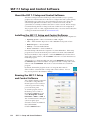
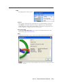
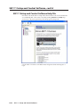
Installing the SSP 7.1 Setup and Control Software............................................... 5-2
Running the SSP 7.1 Setup and Control Software................................................. 5-2
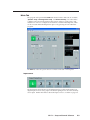
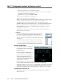
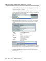
Main Tab. .................................................................................................................................... 5-3
Input source.......................................................................................................................... 5-3
Tone Controls........................................................................................................................ 5-4
Analog Input Gain................................................................................................................ 5-4
Input/Output Information Bar............................................................................................. 5-5
Input status..................................................................................................................... 5-5
Output status.................................................................................................................. 5-6
Master Volume and Mute.............................................................................................. 5-6
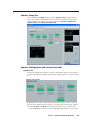
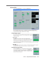
Speaker Setup Tab..................................................................................................................... 5-7
Speaker Configuration tab (second level tab)....................................................................... 5-7
Speaker size.......................................................................................................................... 5-7
Speaker size settings....................................................................................................... 5-7
Crossover......................................................................................................................... 5-8
Speaker configuration......................................................................................................... 5-8
Input/Output information bar............................................................................................. 5-8
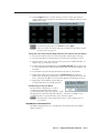
Speaker Delay tab (second level tab)...................................................................................... 5-9
Speaker Distance.................................................................................................................. 5-9
Two person setup (without Lip Sync Offset)............................................................... 5-10
Setup with a Real Time Analyzer (RTA) calibration tool (without Lip Sync Offset).. 5-11
Compensating for Lip Sync Offset............................................................................... 5-11
Input/Output information bar........................................................................................... 5-11
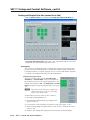
Testing and Output Trim tab (second level tab).................................................................. 5-12
Test signals.......................................................................................................................... 5-12
Selecting test signal source.......................................................................................... 5-12
Selecting speakers to be tested................................................................................... 5-13
Speaker test sequence.................................................................................................. 5-13
Output Trim........................................................................................................................ 5-14
TOC-ii SSP 7.1 • Table of Contents
Input/Output information bar........................................................................................... 5-14
Listening Mode Setup Tab...................................................................................................... 5-15
Input channel...................................................................................................................... 5-15
Listening mode selection................................................................................................... 5-15
Listening mode override.................................................................................................... 5-16
Input/Output information bar........................................................................................... 5-16
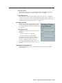
Advanced Tab........................................................................................................................... 5-17
Volume Output Control .................................................................................................... 5-17
Fixed volume................................................................................................................. 5-17
Adjustable..................................................................................................................... 5-17
Front Panel Security Lockout ............................................................................................ 5-17
Factory Defaults ................................................................................................................. 5-18
Dynamic Range Compression............................................................................................ 5-18
Mono Mode Settings ......................................................................................................... 5-18
Mono Source (applies to Analog Input #5 only)......................................................... 5-18
Mono Output................................................................................................................ 5-18
Dolby Pro Logic II/IIx Music Settings ................................................................................. 5-18
Dimension Control........................................................................................................ 5-18
Panorama Control......................................................................................................... 5-19
Center Width Control................................................................................................... 5-19
DTS Neo:6 Settings ............................................................................................................ 5-19
Center Image Control................................................................................................... 5-19
Input/Output information bar........................................................................................... 5-19
Drop down menus................................................................................................................... 5-20
File....................................................................................................................................... 5-20
Exit................................................................................................................................. 5-20
Tools.................................................................................................................................... 5-20
Trace Window............................................................................................................... 5-20
Help..................................................................................................................................... 5-21
Contents........................................................................................................................ 5-21
Extron Home Page........................................................................................................ 5-21
About............................................................................................................................. 5-21
SSP 7.1 Setup and Control Software Help File........................................................ 5-22
Firmware Updates.................................................................................................................... 5-23
Chapter Six • Configuration and Control. ...................................................................... 6-1
Introduction to SIS™ ................................................................................................................. 6-2
Symbols used in this manual.............................................................................................. 6-2
Error messages. .......................................................................................................................... 6-7
Expected Unsolicited Responses.............................................................................................. 6-7
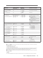
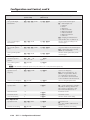
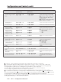
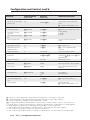
Command/response table for SIS commands. .......................................................... 6-8
Setting Speaker Delay settings using SIS commands. ...................................... 6-15
Two person setup.......................................................................................................... 6-15
Setup with a Real Time Analyzer (RTA) calibration tool............................................ 6-16
Compensating for Lip Sync Offset............................................................................... 6-16
SSP 7.1 • Table of Contents TOC-iii
Table of Contents, cont’d
Setting up Test Sources with SIS Commands.......................................................... 6-17
Using Pink Noise or Dolby Noise test signals.............................................................. 6-17
Using External Source test signals............................................................................... 6-17
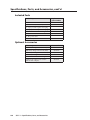
Appendix A • Specifications, Parts and Accessories............................................. A-1
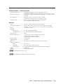
Specifications .............................................................................................................................. A-2
Included Parts. ............................................................................................................................. A-4
Optional Accessories. .............................................................................................................. A-4
Appendix B • Reference Material.........................................................................................B-1
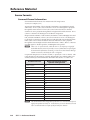
Source Formats.............................................................................................................................B-2
Surround Channel Information...............................................................................................B-2
Dolby Digital Source Formats (
D)......................................................................................B-3
Dolby Digital 5.1...................................................................................................................B-3
Dolby Digital 2/0...................................................................................................................B-3
Dolby Digital 2/0 Surround..................................................................................................B-3
Dolby Digital Surround EX...................................................................................................B-4
DTS Source Formats (DTS).........................................................................................................B-4
DTS 2-Channel......................................................................................................................B-4
DTS Digital Surround............................................................................................................B-4
DTS 96/24..............................................................................................................................B-4
DTS-ES Matrix 6.1.................................................................................................................B-4
DTS 96/24 ES Matrix 6.1........................................................................................................B-4
DTS-ES Discrete 6.1...............................................................................................................B-4
PCM Digital Source Format (PCM)...........................................................................................B-5
2-Channel Source Format (2CH). .............................................................................................B-5
Analog...................................................................................................................................B-5
Digital....................................................................................................................................B-5
Sampling Frequency..................................................................................................................B-5
Listening Mode Options and Usage. ...............................................................................B-6
Listening Mode Options. ..........................................................................................................B-6
Stereo....................................................................................................................................B-6
Mono.....................................................................................................................................B-6
Stereo to All..........................................................................................................................B-6
Mono to All...........................................................................................................................B-6
Dolby Digital 5.1...................................................................................................................B-6
DTS........................................................................................................................................B-7
DTS 96/24..............................................................................................................................B-7
DTS-ES Matrix.......................................................................................................................B-7
DTS 96/24 ES Matrix..............................................................................................................B-7
DTS-ES Discrete.....................................................................................................................B-7
Dolby Digital EX...................................................................................................................B-7
Dolby Pro Logic.....................................................................................................................B-7
Dolby Pro Logic II/IIx Movie or Music..................................................................................B-8
Dimension Control..........................................................................................................B-8
Center Width Control.....................................................................................................B-8
Panorama Control...........................................................................................................B-8
TOC-iv SSP 7.1 • Table of Contents
Dolby Digital Pro Logic IIx Movie or Music.........................................................................B-8
DTS + Dolby Pro Logic IIx Movie or Music...........................................................................B-9
DTS 96/24 + Dolby Pro Logic IIx Movie or Music.................................................................B-9
DTS + Dolby EX.....................................................................................................................B-9
DTS 96/24 + Dolby EX...........................................................................................................B-9
DTS Neo:6 Cinema or Music.................................................................................................B-9
Center Image Control.....................................................................................................B-9
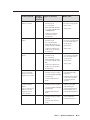
Listening Modes Usage...........................................................................................................B-10
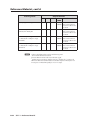
Listening Mode and Output Channels. ................................................................................B-13
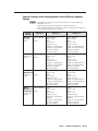
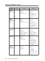
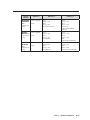
Source Formats and Listening Modes with Different Speaker Setups.............................B-15
Appendix C • Index and Glossary..........................................................................................C-1
Index...................................................................................................................................................C-2
Glossary............................................................................................................................................C-6
All trademarks mentioned in this manual are the properties of their respective owners.
68-1339-01
Rev. A
06 09
SSP 7.1 • Table of Contents TOC-v
Table of Contents, cont’d
TOC-vi SSP 7.1 • Table of Contents
1
Chapter One
Introduction
About This Manual
About the SSP 7.1
SSP 7.1 Features
PRELIMINARY
SSP 7.1
Introduction
About this Manual
This manual contains information on how to mount, install, configure and operate
the Extron® SSP 7.1.
In this manual, unless otherwise specified, the terms SSP 7.1, sound processor, or
surround sound processor all refer to the SSP 7.1 unit.
About the SSP 7.1
The SSP 7.1 is a 7.1 channel Surround Sound processor with four digital inputs and
one analog input. A variety of selectable listening modes can be changed to match
the source format.
The unit can accept 2 channel analog signals, as well as digital PCM signals, and
output them through various matrix decoding mode options for use in 5.1 to 7.1
system configurations.
The SSP 7.1 can decode and process licensed, branded digital source formats from
Dolby® Digital1 and DTS®2, in their originally encoded formats. These include:
• Dolby Digital 2/0
• Dolby Digital 2/0 Surround
• Dolby Digital 5.1
• Dolby Digital Surround EX™1
• DTS 2-channel
• DTS Digital Surround®2
• DTS 96/24™2
• DTS-ES®2 Matrix 6.1
• DTS 96/24 ES Matrix 6.1
• DTS-ES Discrete 6.1
SSP 7.1 Features
Advanced Control and Configuration — The SSP 7.1 Windows® Control Program
provides additional configuration options beyond those available through front
panel control.
Four digital audio inputs — The unit accepts four digital inputs through two
optical (TosLink®) digital inputs and two S/PDIF coaxial (RCA) digital inputs.
Dolby Digital and DTS playback — The unit is able to decode and process source
format from Dolby Digital and DTS, in their originally encoded formats.
Matrix decoding — The surround sound processor can decode stereo signals to
produce multi-channel output.
Manufactured under license from Dolby Laboratories. Dolby, Pro Logic, and the double-D
1
symbol are trademarks of Dolby Laboratories.
2
Manufactured under license under U.S. Patent #’s: 5,451,942; 5,956,674; 5,974,380; 5,978,762;
6,226,616; 6,487,535; 7,003,467; 7,212,872 & other U.S. and worldwide patents issued & pending.
DTS, DTS Digital Surround, ES, and Neo:6 are registered trademarks and the DTS logos,
Symbol and DTS 96/24 are trademarks of DTS, Inc.
© 1996-2008 DTS, Inc. All Rights Reserved.
1-2
SSP 7.1 • Introduction
Downmix multichannel source formats — Downmixing produces a mixed stereo
or mono channel with an additional option to redistribute the downmixed signal to
all channels.
Configurable analog input — Input 5 accepts balanced/unbalanced stereo analog
input and can be configured to accept one or two balanced/unbalanced mono
inputs through a captive screw connector. The mono source can be left, right, or a
mix summed of the two.
Adjustable gain for analog input — The input gain is adjustable from 0 to +24 dB
using the front panel controls or the SSP 7.1 Setup and Control Software.
Multiple Listening Modes — Not all listening modes are compatible with certain
input signals. The listening mode depends not only on the format of the source
material but also on the speaker configuration of the setting. Only those listening
modes that are compatible for a given input are available for that signal. The
SSP 7.1 comes with factory default listening modes that have been matched to the
source format to take into account source format and speaker configuration.
Listening Mode Override — The Listening Mode Override customizes the
listening mode to the needs of the source format, speaker configuration, the venue,
and the listener’s personal preferences. Selections made through the front panel
can be further refined by the SSP 7.1 Setup and Control Software.
This feature can be used to associate a specific listening mode with each input type,
allowing the user to switch quickly to the listening mode that suits each input type
for a given room configuration and the individual user preferences.
Test Signals — Pink noise, Dolby noise (generated by the SSP 7.1) and external test
signals allow full calibration of each output channel.
Speaker Compensation Delay — The signal to each output channel can be
individually delayed so that the sound from all speakers is synchronized when it
reaches the listener.
Lip Sync Offset — This feature delays an audio signal so that it is resynchronized
with a video signal that has been delayed by video processing.
SSP 7.1 • Introduction
1-3
Introduction, cont’d
1-4
SSP 7.1 • Introduction
2
Chapter Two
Mounting
Mounting the SSP 7.1
PRELIMINARY
SSP 7.1
Mounting
Mounting the SSP 7.1
The sound processor is 1U high, a half rack wide and 6" deep, for easy mounting in
a range of convenient locations.
Tabletop placement
Attach the four included rubber feet to the bottom of the unit and place it in any
convenient location.
Rack mounting
UL guidelines for rack mounting
The following Underwriters Laboratories (UL) guidelines are relevant to the safe
installation of the transmitter in a rack:
1. Elevated operating ambient temperature — If the unit is installed in a closed
or multi-unit rack assembly, the operating ambient temperature of the rack
environment may be greater than room ambient temperature. Therefore, install
the equipment in an environment compatible with the maximum ambient
temperature (Tma: +122 ° F, +50 ° C) specified by Extron.
2. Reduced air flow — Install the equipment in the rack so that the equipment gets
adequate air flow for safe operation.
3. Mechanical loading — Mount the equipment in the rack so that uneven
mechanical loading does not create a hazardous condition.
4. Circuit overloading — Connect the equipment to the supply circuit and
consider the effect that circuit overloading might have on overcurrent protection
and supply wiring. Give appropriate consideration to the equipment nameplate
ratings when addressing this concern.
5. Reliable earthing (grounding) — Maintain reliable grounding of rack-mounted
equipment. Pay particular attention to supply connections other than direct
connections to the branch circuit (such as the use of power strips).
2-2
SSP 7.1 • Mounting
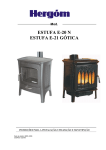
Rack mounting procedure
The unit can be mounted in the front or rear of:
• RSU 126 (6"deep, 1U rack shelf kit: part # 60-190-10)
• RSB 126 (6" deep, 1U basic rack shelf: part # 60-604-10)
• RSU 129 (9.5" deep, 1U rack shelf kit: part # 60-190-01)
• RSB 129 (9.5" deep, 1U basic rack shelf: part # 60-604-01)
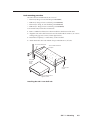
To mount the unit, follow these instructions:
1. Remove rubber feet if these have been installed on the bottom of the unit.
2. Align the unit on the shelf and secure it to the shelf with two 4-40 x 3/16" screws
in diagonally opposite corners (see the figure below).
3. Install false faceplate(s) or other unit(s) to the rack shelf.
4. Attach the shelf to the rack with the four provided 10-32 x 3/4" bolts.
1U Universal Rack Shelf
1/2 Rack Width Front False
Faceplate
Front false
faceplate
uses 2
screws.
(2) 4-40 x 3/16"
Screws
Use 2 mounting holes on
opposite corners.
Installing the SSP 7.1 on shelf rack
SSP 7.1 • Mounting
2-3
Mounting, cont’d
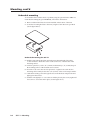
Under-desk mounting
To mount the SSP 7.1 under a desk or podium, using the optional Extron MBU 125
under desk mounting kit (part # 70-077-01), follow these instructions:
1. Remove rubber feet if these have been installed on the bottom of the unit.
2. Secure the mounting brackets to the unit, using the four 4-40 screws provided
(see the figure below).
Under-desk mounting the SSP 7.1
3. Hold the unit with the brackets attached against the underside of the table
or other furniture. Mark the location of the screw holes of the bracket on the
mounting surface.
4. Drill four pilot holes, each 3/32" (2.4 mm) in diameter by 1/4" (6.3 mm) deep in
the mounting surface at the marked screw locations.
5. Insert #8 wood screws into the four pilot holes. Tighten each screw into the
mounting surface until just less than 1/4" (6.3 mm) of the screw head protrudes.
6. Guide the mounting screws through the slots in the brackets and place the unit
tight against the surface.
7. Slide the unit slightly in or out so that it is held in place by the screws; tighten all
four screws to secure the unit in place (see the figure above).
2-4
SSP 7.1 • Mounting
3
Chapter Three
Features
Front Panel Features
Rear Panel Features
Front Panel Operations
PRELIMINARY
SSP 7.1
Features
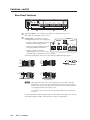
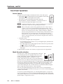
Front Panel Features
SOURCE
MODE OVERRIDE
D
DOWNMIX
1
2
INPUTS
3
VOLUME
4
5
CLIP
PL II/IIx
DTS
PCM
DTS NEO:6
2-CH
TO ALL
SSP 7.1
CONFIG
SURROUND SOUND PROCESSOR
1
a
b
2
4
3
5
Config Port — The SSP 7.1 can be configured using Extron Simple Instruction
Set (SIS™) commands through this 2.5 mm Tip Ring Sleeve (TRS) mini jack plug
(or through the 3-pole captive screw connector on the rear panel). For more
information about SIS commands, see chapter 6.
Input Source Format Indicator — Four LEDs identify the source signal format as:
• Dolby Digital (
D)
• DTS
• PCM
• 2-Channel (2-CH)
For more information about source formats, see "Front Panel Operations" on
page 3-6 and "Source Formats" on page B-2.
c
Mode Override Selector — The SSP 7.1 comes with factory default listening modes
associated with particular source formats. However, these default modes can
be overridden by the user through the mode override button. The user defined
override that is currently selected is shown by this group of LEDs. When no mode
override is chosen, none of the LEDs light.
The available mode overrides are:
• Downmix
• Dolby Pro Logic II/IIx (
PL II/IIx)
• DTS Neo:6 (DTS NEO:6)
• To All
Selecting an appropriate listening mode depends on the source format and on the
speaker configuration. For more information about setting the Mode Override, see
"Front Panel Operations" on page 3-6 and "Listening Mode Options and Usage" on
page B-6.
When used in conjunction with the Input buttons, the Mode Override button is
used to mute all outputs (see page 3-8).
The Mode Override is used to perform a complete system reset (see "Complete
System Reset" on page 3-9).
d
Input Selections — Push one of the buttons to select between 5 possible audio
inputs. The LED next to the currently active input lights. For more information
about input selection, see page 3-8.
In conjunction with the Mode Override button, the Input buttons are used to mute
all outputs (see page 3-8).
The Input buttons are also used to enable or disable the Front Panel Security
Lockout (Executive Mode). For more information, see page 3-10.
In conjunction with the Volume Adjust Knob, the analog input (Input #5) is used to
set analog input gain level for the analog source (see page 3-10).
3-2
SSP 7.1 • Features
e
Volume Adjust Knob and LED Bar /Analog Input Gain Level Control and LED
Bar — The rotary encoder adjusts the output volume (see page 3-9).
Together with the analog input button (Input #5), the knob also adjusts the analog
input gain level for the analog source (see page 3-10).
SSP 7.1 • Features
3-3
Features, cont’d
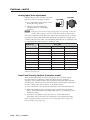
Rear Panel Features
INPUTS
100-240V .5A
50/60Hz
DIGITAL
3
2
1
6
OUTPUTS
SSP 7.1
ANALOG
L
5
R
FRONT
L
R
CENTER
L
SIDE
L
R
BACK
R
SUB
WOOFER
RS-232
Tx Rx
4
8
7
9
f
AC Power Input — Use an IEC power cable to connect the processor to a
100 ‑ 240 VAC, 50 - 60 Hz, power source.
g
Audio Inputs — The SSP 7.1 accepts
four digital inputs and one analog input:
INPUTS
DIGITAL
• Inputs 1 and 2 accept digital signals
through S/PDIF optical cables.
ANALOG
3
• Inputs 3 and 4 accept digital signals
through S/PDIF coaxial cables.
• Input 5 accepts a balanced or
1
unbalanced, stereo or mono, analog
input through a 5-pin captive screw connector.
2
L
5
R
4
The following diagram shows the correct wiring for different input signals:
R
Unbalanced Stereo Input
L
Do not tin the wires!
Balanced Stereo Input
Tip
Ring
Sleeve
L
Tip
Sleeve
R
L
Tip
Sleeve
Tip
Ring
Sleeves
Tip
Ring
L
Tip
Sleeve
R
R
Unbalanced Mono Input
Balanced Mono Input
(high impedance)
N The length of the exposed wires in the stripping process is critical. The ideal
length is 3/16" (5 mm). Any longer and the exposed wires may touch, causing
a short circuit between them. Any shorter and the wires can be easily pulled out
even if tightly fastened by the captive screws.
Do not tin the wires. Tinned wire does not hold its shape and can become loose
over time.
For more information about input formats, see the "Front Panel Operations" section,
later in this chapter and the "Source Formats" section of Appendix B.
3-4
SSP 7.1 • Features
h
Audio Outputs — Outputs are balanced/unbalanced line level analog signals that
feed into multi-channel amplifiers for configurations up to 7.1 surround sound. For
more information about speaker configuration, see pages 4-2 and 4-3.
OUTPUTS
FRONT
L
R
CENTER
L
SIDE
R
L
BACK
R
SUB
WOOFER
Individual output settings are configured through the SSP 7.1 Setup and Control
Software (see page 5-7) or SIS commands (see page 6-9):
Mono — output is through the center channel only but can be reconfigured to be
output through the left and right front channels. In the absence of a center channel,
mono is also output through the left and right front channels.
2-Channel (Stereo) — only the front left and front right channels are used.
3.0 to 3.1 Surround Configurations — Audio is output through front left, front
right, and center channels with (3.1) or without (3.0) a subwoofer.
4.0 to 5.1 Surround Configurations — Audio is output through a combination of
front left and right, side left and right, center and subwoofer channels.
6.0 to 6.1 Surround Configurations — Adds a back channel to 5.0 or 5.1
configurations. The back left channel receives the sixth channel information and
serves as the center back speaker in this configuration.
7.0 to 7.1 Surround Configurations — both the back left and right channels are
active. Listening modes designed for 6.1 channel outputs pass the same signal to
both the back left and right channels. Listening modes designed for 7.1 channel
outputs pass separate signals to each channel to produce a stereo back sound effect.
2.0 to 2.1 Surround Configurations — Audio is output through front left and front
right channels with (2.1) or without (2.0) a subwoofer.
For more information about speaker configuration and output formats, see the
"Listening Mode Options and Usage" section of Appendix B.
i
RS-232 Port — The SSP 7.1 can be configured using the SSP 7.1 Setup
and Control Software or SIS commands, using this 3-pole captive screw
connector (or the 2.5 mm Tip Ring Sleeve (TRS) mini jack plug on the
front panel).
RS-232
Tx Rx
For more information about the SSP 7.1 Setup and Control Software, see
chapter 5. For more information about SIS commands, see chapter 6.
SSP 7.1 • Features
3-5
Features, cont’d
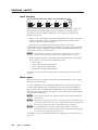
Front Panel Operations
Source format
The bank of four LEDs lights to identify the format of the audio input:
• Dolby Digital ( D): Dolby Digital 2/0, Dolby Digital 2/0 Surround,
Dolby Digital 5.1, or Dolby Digital Surround EX.
• DTS: DTS 2-Channel, DTS Digital Surround, DTS 96/24,
DTS‑ES Matrix 6.1, DTS 96/24 ES Matrix, or DTS‑ES Discrete 6.1.
SOURCE
D
DTS
PCM
2-CH
• PCM: 2-channel uncompressed digital source format.
N A digital signal that does not have a supported sampling rate or is compressed
PCM will be considered an unrecognized signal and muted.
N When a DVD player is paused during playback, the SSP 7.1 may or may not
continue to receive source format information from the DVD player. Some
players continue to send the same source format information in a loop, allowing
the SSP 7.1 to retain the previous settings. Other DVD players completely
disconnect the signal from the SSP 7.1 (unlocked state), so that the active input
blinks as if there is no connection present. The remainder of DVD players
change the source output to PCM without an actual signal being sent (Digital
Silence). During Digital Silence, the PCM LED will light but the 2-CH source
LED will not light.
• 2-Channel (2-CH):
oo Any source coming through analog input #5
oo If a PCM digital signal is present on any of the digital inputs, both the PCM
and the 2-CH LEDs light.
oo If a Dolby Digital 2/0 or Dolby Digital 2/0 Surround source is present, both
the
D and the 2-CH LEDs light.
oo If a DTS 2-Channel source format is present, both the DTS and the 2-CH
LEDs light.
To understand more about source formats, see pages B-2 to B-4 of Appendix B.
Mode Override selection
The SSP 7.1 has a wide range of listening modes, although
not all listening modes are compatible with every source
format. The system’s speaker configuration may further
limit which listening mode is available for a source
format. Other factors such as the room layout and listener
preferences may also influence the listening mode selection.
MODE OVERRIDE
DOWNMIX
PL II/IIx
DTS NEO:6
TO ALL
The SSP 7.1 has default listening modes associated with each source format. The
front panel provides the user with a limited set of Mode Override settings. These
can change the listening mode that is associated with a specific combination of
source format and input. The override selections can be further defined using the
SSP 7.1 Setup and Control Software, or SIS commands.
The new, user-defined listening mode will continue to be associated with that
source format until Mode Override is used, again, to associate a new listening mode
with the source format.
To learn more about listening modes, see "Listening Mode Options" on pages B-6
to B-9 of Appendix B. To learn how listening modes depend on both source format
and speaker configuration, see "Source Formats and Listening Modes with Different
Speaker Setups" on pages B-15 to B-17.
3-6
SSP 7.1 • Features
To select a listening mode:
1. Use the push button to toggle through the available listening modes. If no
mode override is selected, none of the LEDs light, indicating that a user-defined
listening mode is in use. Otherwise, one of the four LEDs shows the current
selection.
2. Release the button when the desired LED is lit to select that listening mode. If a
listening mode is not an available option for the current input source, toggling
will skip that mode and go to the next available mode.
3. If required, further define the selection using the SSP 7.1 Setup and Control
Software (see chapter 5).
The mode override selections that are available through the front panel are:
• Downmix (DOWNMIX) — downmixes any multi channel source format (digital
inputs only). It also downmixes a 2-channel source format, if the listening mode
is set to Mono.
It is further defined from the Setup and Control Software (see chapter 5).
Options include:
oo Stereo, output on left front and right front channels.
oo Mono, output to center channel only or to left and right front channels,
equally.
• Dolby Pro Logic II/IIx ( PL II/IIx) — uses Dolby Pro Logic II or
Dolby Pro Logic IIx surround processing technology.
oo Dolby Pro Logic II extends 2-channel sources to output 5.1 channels. It can
be further defined by control software as either Dolby Pro Logic II Movie
(default) or Dolby Pro Logic II Music.
oo Dolby Pro Logic IIx extends 2-channel sources to output 6.0 to 7.1 channels
(depending on the speaker setup). It can be further defined by control
software as either Dolby Pro Logic IIx Movie or Dolby Pro Logic IIx Music.
oo Dolby Pro Logic IIx also provides an extended surround option for multichannel sources such as DTS Digital Surround or Dolby Digital 5.1.
• DTS Neo:6 (DTS NEO:6) — uses DTS Neo:6 surround processing technology
to extend analog or 2-channel digital source formats (PCM, Dolby Digital 2/0,
Dolby Digital 2/0 Surround, DTS 2-Channel) to output up to 7.1 channels. It
is further defined by control software as either DTS Neo:6 Cinema (default) or
DTS Neo:6 Music.
• To All (TO ALL) — distributes a mono or 2-channel source to all applicable
channels:
oo Mono sources are sent to all available output channels, including center.
oo 2-channel sources are sent to all stereo pairs only.
oo Multichannel sources are downmixed and output to "Mono to All" or "Stereo
to All", as defined by the user.
oo Digital or analog stereo sources may be output to "Mono to All" or "Stereo
to All", as defined by the user. If "Mono to All" is selected, the signal is
downmixed to mono before being output to all channels.
N If an analog mono source is on the left channel, "Stereo to All" listening mode
outputs only to the left channels of available stereo pairs. A right channel analog
mono source is output only to the right channels of available stereo pairs.
SSP 7.1 • Features
3-7
Features, cont’d
Input selection
1
2
INPUTS
3
4
5
CLIP
The five buttons allow the user to select between five possible audio inputs. The
green LED next to the button lights to show which input is currently active.
The SSP 7.1 accepts four digital inputs and one analog input (see Rear Panel
Features on page 3-4):
• Inputs 1 and 2 accept digital signals through S/PDIF optical cables. The optical
cable will support TosLink® or TosLink compatible optical connectors that
conform to IEC-958, S/PDIF standards.
• Inputs 3 and 4 accept digital signals through S/PDIF coaxial cables.
All four digital inputs accept 16-24 bits PCM audio at 32, 44.1, 48, 88.2, and 96 kHz
sample rates. They are designed to support Dolby Digital EX, DTS-ES Matrix 6.1,
and DTS-ES Discrete 6.1 source formats.
N For digital inputs, if there is no valid clock signal at the input and no lock is
achieved, the LED associated with the source will blink twice per second.
• Input 5 accepts a balanced or unbalanced analog input through a 5-pin captive
screw connector. The unit can be configured to accept
oo a stereo signal
oo a mono signal from the right channel
oo a mono signal from the left channel
oo a mixed sum of right and left channels
The input can also be selected using the SSP 7.1 Setup and Control Software (see
page 5-3).
Mute output
When the mute state is enabled, all channels are muted simultaneously. To toggle
between mute and unmute:
1. Press and hold the active input button (the button next to the LED that is lit).
2. While still holding the active input button, press the Mode Override button.
When the mute state is enabled, the individual LEDs of the Volume Adjustment
LED bar light in sequence from the top down. This scrolling down pattern repeats
while the mute state persists.
N Selecting another input button while the mute function is enabled, disables the
mute function.
N Adjusting the volume control encoder to change the volume (or the analog input
gain) settings while the mute function is enabled, disables the mute function and
increases (or decreases) the volume (or gain) from its previous setting.
N If SIS commands have been used to mute a specific channel, muting and
unmuting all channels will also unmute the channel that was specifically muted.
It will not remain in its previously muted state.
All channels can also be muted using the SSP 7.1 Setup and Control Software (see
page 5-6).
3-8
SSP 7.1 • Features
Complete system reset
The SSP 7.1 has three levels of System Reset.
Standard System Reset — all parameters that can be adjusted by the control
program are reset to default
Factory Reset — in addition to resetting all the parameters of the standard system
reset, the baud rate for communicating with the computer is also reset.
Complete System Reset — in addition to resetting all the parameters of the factory
reset, the firmware is reset to the factory-installed version.
The standard and factory resets are performed using SIS commands (see page 6-14).
To perform a complete system reset, hold the Mode Override button while shutting
off and restoring power.
Volume adjustment
Use the rotary encoder to adjust the output volume from
0 (-100 dB) to 100 (0 dB). The default setting is 50 (-50 dB).
VOLUME
The degree to which the volume is incremented/decremented for
each step the encoder is turned, depends on the current volume
setting (see the last column in the table below).
As the volume increases or decreases, the LED bar lights to
indicate the current volume range, as shown in the table below.
As the volume is increased or decreased within a volume range, the top LED
flashes once. If the knob is turned past maximum volume, all 8 LEDs flash, for as
long as the knob continues to be turned.
Volume steps for
each LED dB)
LEDs lit
Increment
(dB/knob step)
>0
All LEDs blink if user tries to turn knob further
0
All 8 LEDs on
-4 to -1
All 8 LEDs on
-9 to -5
Bottom 7 LEDs on
1
-14 to -10
Bottom 6 LEDs on
-19 to -15
Bottom 5 LEDs on
-29 to -20
Bottom 4 LEDs on
2
-49 to -30
Bottom 3 LEDs on
4
-69 to -50
Bottom 2 LEDs on
-99 to -70
Bottom LED on
-100
All LEDs off
5
The Volume can also be controlled using the SSP 7.1 Setup and Control Software
(see page 5-6).
SSP 7.1 • Features
3-9
Features, cont’d
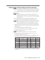
Analog Input Gain adjustment
Alternatively, the rotary encoder controls the
gain level of the analog signal on input 5:
1. Press and hold the Input 5 button, while
turning the rotary encoder.
VOLUME
5
CLIP
2. Adjust the gain from 0 dB (fully
counterclockwise) to +24 dB (fully
clockwise).
N If the gain level is turned too high, clipping may occur (depending on the input
volume). When clipping occurs, the red LED above the Input 5 button lights.
The LED bar lights from the bottom up to indicate the current gain level. No LEDs
lit indicates no gain (0 dB); all the LEDs lit indicates maximum gain (24 dB). Each
solidly lit LED represents 3 dB. A slowly blinking LED indicates an additional 1 dB
or a quickly blinking LED indicates an additional 2 dB:
Number of
LEDs lit solidly
Gain (dB)
No Blinking
Slow Blinking
Fast Blinking
8
24
-
-
7
21
22
23
6
18
19
20
5
15
16
17
4
12
13
14
3
9
10
11
2
6
7
8
1
3
4
5
None
No LEDs lit: 0 dB
1
2
The Analog Input Gain can also be controlled using the SSP 7.1 Setup and Control
Software (see page 5-4).
Front Panel Security Lockout (Executive mode)
When Front Panel Security Lockout is enabled, the user is unable to change
the input selection or adjust the volume from the front panel. If the user
attempts to change either, with this feature enabled, all the input LEDs will flash
simultaneously. The lockout does not block changes made using SIS commands or
the SSP 7.1 Setup and Control Software. To enable this feature:
1. Press and hold the active input button (the button next to the LED that is lit).
2. While still holding the active input button, press and hold any other input
button. All the LEDs blink in ascending order (from 1 to 5) and then the active
input button lights.
3. The feature is disabled in exactly the same way. All the LEDs blink in
descending order (5 first and 1 last) and then the active input button lights.
The Front Panel Security Lockout can also be set, using the SSP 7.1 Setup and
Control Software (see page 5-17).
3-10
SSP 7.1 • Features
4
Chapter Four
Setup
Setup Options
PRELIMINARY
SSP 7.1
Setup
Setup Options
Chapter 3 describes some basic configuration that can be carried out using the
front panel controls of the SSP 7.1. The SSP 7.1 Setup and Control Software offers
all of those choices and additional options that are not available through the front
panel. Extron strongly recommends that the Control Program is used to make any
configuration changes to the SSP 7.1. (See chapter 5, "SSP 7.1 Setup and Control
Software").
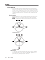
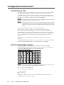
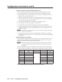
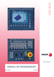
Speaker setup
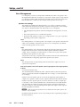
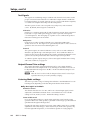
The following figures show the recommended speaker placement, relative to the
listener, for a five, six, or seven speaker system and for subwoofer placement.
N All speakers should be angled inwards so that they face towards the listener.
L
C
0°
R
22°
30°
LS
90°
RS
110°
Five Speaker Setup
L
C
0°
LS
R
22°
30°
90°
RS
110°
180°
CB
Six Speaker Setup
Abbreviations
C = Center; CB = Center Back (Six Speaker Setup only); L = Left; LB = Left Back
(Seven Speaker Setup only); LS = Left Side; R = Right; RB = Right Back (Seven
Speaker Setup only); RS = Right Side; SW = Subwoofer
4-2
SSP 7.1 • Setup
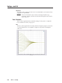
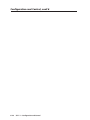
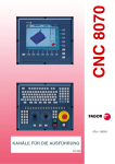
L
C
R
0°
22°
30°
LS
90°
RS
110°
150°
135°
LB
RB
Seven Speaker Setup
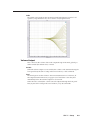
L
R
C
RECORDING
Progressive
DVD-RW/-R
Cinema
Precision
SW
RS
LS
RB
CB
LB
Subwoofer placement
N To produce a good bass response from the subwoofer, it should be located at the
front of the listening room, somewhere between either corner and a point about
one third of the way along the front wall.
N The output channel used for the Left Back speaker (in 7.1 configurations) is also
used for the Center Back speaker (in 6.1 configurations).
SSP 7.1 • Setup
4-3
Setup, cont’d
Bass Management
Low frequency sounds are usually better handled by the subwoofer speaker. Bass
Management handles the low frequency component of input signals, along with the
Low Frequency Effects (LFE) information encoded in the source format and passes
that information to a subwoofer (if available) and to speakers set to Large.
Speaker size settings
This feature sets whether Bass Management is on or off for a particular speaker,
which defines the frequency range that is output from that speaker. These settings
also enable or disable the subwoofer and set the crossover frequency.
• Left and Right Front speakers and Left and Right Surround Speakers are set in
pairs.
• The Center speaker is set as an individual speaker.
• Back Surround speaker(s) can be set as a single speaker or as a pair of speakers,
depending on the system configuration.
Small
Bass Management is on for that speaker. The output to each speaker (other than the
subwoofer) is limited to frequencies above the Crossover Frequency. By default,
center and side speakers are set to small.
Large
Bass Management is off for that speaker. This mode allows the full range of audio
frequencies from the audio source to be fed through the individual channel’s
output. This is sometimes set in the absence of a subwoofer as part of the system.
By default, front speakers are set to large.
All speakers set to Large, except the Center channel, will receive the summed audio
from the filtered low frequency signals from speakers set to Small.
None
This mode prevents any signal being sent to that channel’s output. It is not an
option for front speakers.
One Small Speaker, Two Small Speakers, One Large Speaker, Two Large Speakers,
or None
(Surround back speakers only)
This mode determines whether the audio output channels for the back speaker(s)
will be passed to the Left Back and Right Back (in 7.1 setups) or to the Center Back
(in 6.1 setups).
If either of the one speaker options are chosen, the highest possible number of
outputs is 6.1 speakers. In this case, the output is directed to the left back channel.
If either of the two speaker options are chosen, the SSP 7.1 is able to output up to
7.1 channels. Source formats with discrete or matrix mixed 6.1 encoded channels
will output the surround back channel signal equally to the left and right back
channels. Dolby Pro Logic IIx listening mode option will output a stereo signal to
the left and right back channels.
N If the side surround speakers have been disabled, the back speaker options will
also be disabled.
By default, the back speaker is set to none, which prevents a signal being output on
the back channel(s).
4-4
SSP 7.1 • Setup
Subwoofer
This option allows the subwoofer to be enabled or disabled. When the subwoofer
is enabled, the signal contains filtered low frequency signals from speakers set to
small in addition to the LFE signal from the source format. If the subwoofer is
absent or disabled, the LFE signal is mixed with the bass information of all speakers
in the system that are set to large, except the center speaker.
N When the Surround Side and Surround Back speakers are set to None, all
multichannel input signal formats are downmixed and output on all the system’s
remaining channels.
In addition, in the absence of a Center channel, mono signals, are output equally
between the Front Left and Front Right channels. Multichannel sources are
downmixed to all remaining channels, but Mono to All and Stereo to All
options are disabled. Choosing Mono listening mode will first downmix the
multichannel source and output it to front left and right channels equally as a
dual mono signal.
Crossover Frequency
The Crossover Frequency sets the boundary below which the low frequency
signals from designated output channels are incorporated into Bass Management.
Low frequency signals are only taken from speakers that have been set to Small
(see Speaker size settings, above). The Bass Management signal is passed to the
subwoofer (if present) and speakers that have been set to Large (except for the
center speakers).
The crossover frequency can be adjusted within the range of 40 Hz to 250 Hz, with
a default setting of 100 Hz. Speakers set to small (see "Speaker size settings", on the
opposite page) will play only signals above the set frequency.
N The LFE information from a multi-channel source format is not affected by
the Crossover Frequency. The LFE info is mixed with low passed signals from
speakers set to Small after the Low Pass Filter is applied to those speakers.
Speaker delay settings
The speaker delay settings adjust the signal delay for each speaker individually
(from 0 to 100 ms). The default setting for each speaker is 0 ms. The two main
reasons to adjust the signal delay are:
Compensation Delay — In a room where speakers are not equidistant from the
listener, sound from the closest speaker reaches the listener before sound from the
farthest speaker. This adjustment delays the signals going to individual speakers:
the signal to the speaker farthest from the listener is not delayed while speakers
that are closer to the listener, are delayed more. This ensures that the sound from
each speaker reaches the listener at the same time.
Lip Sync Offset — Processing video signals often delays the video signal, relative
to the audio signal. The Lip Sync Offset delays audio signals to every output
channel by the same amount to compensate for the delay to the video signal and to
resynchronize the audio and video outputs.
If a particular setup requires both types of compensation, it is recommended that
the individual speaker’s compensation delay is set first before readjusting all
speakers for Lip Sync offset.
N The total speaker delay (Compensation Delay + Lip Sync Offset) must not
exceed 100 ms.
To configure these settings using the SSP 7.1 Setup and Control Software, see
page 5‑9.
SSP 7.1 • Setup
4-5
Setup, cont’d
Test Signals
Test signals are used during setup to calibrate each channel’s levels and to ensure
proper connection between the SSP 7.1’s individual output channels and the line
level input channels of an audio signal processor, a receiver with built in amplifier,
or a stand alone amplifier that will power the loudspeakers.
The three options for test source are pink noise, Dolby noise, and an external
source. By default, the test signal is switched off.
Pink Noise
Pink noise is a random signal with all audio frequencies present, that is generated
by the SSP 7.1. It provides equal energy per octave to provide a flat response
over all frequencies. The main purpose of pink noise is to calibrate the speaker’s
interaction with its given environment.
Dolby Noise
Dolby noise provides a bandpass-filtered noise, centered at 750 Hz with a
12 dB/octave role off. This signal is also generated by the SSP 7.1 and is used to set
speakers to the same level when calibrating the room.
External
This option requires an external calibration source, such as an audio calibration
disk that is played through a selected input source. These calibration disks are
usually used to test specific decoding mode outputs and when the External Source
option is chosen, the speakers that receive the test signal can be specified.
To calibrate speaker output, using any of these test signals with the SSP 7.1 Setup
and Control Software, see page 5‑12.
Output Channel Trim settings
This control adjusts the output channel trim level for each output channel to
match the levels to the unique needs of any listening environment. The level can
be adjusted within the range from -24 dB to +12 dB. The default setting for each
speaker is 0 dB.
N When the level is set above 0 dB, the Output Volume control is reduced by an
equivalent amount to prevent the possibility of clipping.
Listening Mode settings
The SSP 7.1 provides a range of settings that refine the sound distribution for each
listening mode, depending on the decoding mode that has been selected.
Dolby Pro Logic II or IIx Music
Dimension control
This feature alters the ratio of L+R to L-R for two-channel input signals, which
adjusts the sound field towards the front or towards the back. The available
settings are front, neutral, or back. The default setting is neutral.
Center width control
Pro Logic decoding produces a single center signal that comes from the center
speaker. If there is no center speaker, a "phantom" center image is produced that is
split between the right and left speakers.
If right, left, and center speakers are present, center width control allows variable
adjustment of the center image so that is heard only from the center speaker, only
from the right and left speakers, or from all three speakers in varying degrees.
4-6
SSP 7.1 • Setup
There are up to eight different settings, with each corresponding to a specific
calculation angle (Φ). When the setting is 0, the sound comes from the center
speaker, when the setting is 7, the sound is from the L/R speakers. The default
setting is 3.
Control
Position
Calculation
Angle (Φ)
C Level (dB)
L/R Level (dB)
0
0
0.0
Off
1
20.8
-0.6
-12.0
2
28.0
-1.1
-9.6
3
36.0
-1.8
-7.6
4
54.0
-4.6
-4.8
5
62.0
-6.6
-4.1
6
69.2
-9.0
-3.6
7
90.0
Off
-3.0
N The level of the center speaker (C Level) is related to cosine Φ. The level of the
left and right speakers (L/R Level) is related to sine Φ.
Panorama control
This feature extends the Center Width Control, so that all or part of the center
image can be heard from the side surround speakers for a "wraparound" effect. The
feature may be on or off. The default setting is Off.
DTS Neo:6 Music or Cinema
Center image control
The Center Image control varies the amount of attenuation applied to the Left and
Right channel information of the input source that is used for creating the output
Center channel effects. When it is set to 0, the mixed input signal information,
intended for use in creating the Center output channel of the DTS Neo:6 listening
modes, is filtered back to the Front Left and Right output channels. This creates
the effect of spreading the centralized audio signal across all three front output
channels. When this control is set to 10, the matrixed information intended for the
Center output channel effects is fully attenuated, allowing the Center channel to
dominate and creating a more centralized effect from the front channels.
The default setting for DTS Neo6: Music is 3. The default setting for
DTS Neo6: Cinema is 10.
Dynamic Range Compression control
(Only with Dolby Digital and DTS source formats that have a Dynamic Range
Compression flag)
This control adjusts the gain applied to Dolby Digital or DTS listening modes
to compress the signal outputs during the decoding process. The three possible
settings are none, minimum, and maximum. The default setting is None.
None
The signal is uncompressed and is played with the full original dynamic range.
Minimum
The audio is partially compressed. In this mode, the volume of the loudest
passages is reduced but quieter passages are kept at their original level. This level
is recommended for normal listening.
SSP 7.1 • Setup
4-7
Setup, cont’d
Maximum
The audio is fully compressed. This level is recommended for environments where
loud audio is not permitted.
N DTS source formats have only two states (on and off) for dynamic range
compression. Therefore, minimum and maximum both apply the same dynamic
range compression.
Tone Controls
These controls regulate the Bass and Treble settings for the system. To adjust the
bass or treble tone controls, see page 5-4.
Bass
The Bass control regulates the amount by which low frequency signals are boosted
or cut (see figure below). It is applied to outputs for all speakers, including the
subwoofer.
4-8
SSP 7.1 • Setup
Treble
The Treble control regulates the amount by which high frequency signals for all
speakers, except the subwoofer, are boosted or cut (see figure below).
Volume Output
This control sets the volume of the audio output through all channels, globally, to
either Variable (the default value) or Fixed.
Variable
When the Volume output is set to Variable, the volume can be attenuated using the
front panel knob, the SSP 7.1 Setup and Control Software, or SIS commands.
Fixed
The Fixed option sets the volume to the current attenuation level. Likewise, all
the Output Channel Trim levels (see page 4-6) are fixed at the values they had
immediately before the Volume Output was set to Fixed.
When "Fixed" is selected, the volume cannot be adjusted through the front panel
knob, by the SSP 7.1 Setup and Control Software, or by SIS commands.
SSP 7.1 • Setup
4-9
Setup, cont’d
4-10
SSP 7.1 • Setup
5
Chapter Five
SSP 7.1 Setup and Control
Software
About the SSP 7.1 Setup and Control Software
Installing the SSP 7.1 Setup and Control Software
Running the SSP 7.1 Setup and Control Software
SSP 7.1 Setup and Control Software Help File
Firmware Updates
PRELIMINARY
SSP 7.1
SSP 7.1 Setup and Control Software
About the SSP 7.1 Setup and Control Software
The SSP 7.1 Setup and Control Software provides an intuitive, easy to operate,
graphical user interface that allows the user to configure the audio system quickly
and efficiently. It provides more options than the front panel. The options are
automatically updated in real time so that, as selections are made, only the
options that are currently available to the SSP 7.1 can be accessed. Extron strongly
recommends using the SSP 7.1 Setup and Control Software for all configuration.
The program comes on a disk, supplied with the unit, or it can be downloaded, free
of charge, from the Extron Web site (www.extron.com).
Installing the SSP 7.1 Setup and Control Software
The minimum system requirements for installing the program on the computer are:
• Operating System — Microsoft® Windows® 2000 or higher.
• CPU — Intel® Pentium® II processor with a 400 MHz clock speed or faster.
• Hard Disk space — At least 10 MB
• Memory — At least 64 MB of RAM
• Device connection — Serial COMM Port
Insert the disk provided into the computer’s CD/DVD ROM drive. If the setup
program does not start automatically, run Launch.exe from the CD/DVD ROM
directory in Windows "My Computer". Select the Software tab, locate the SSP 7.1
Setup and Control Software, and click Install. Follow the on-screen instructions to
install the program.
Alternatively, go to the Extron Web site, click on the Download tab, and click on
the Software option in the left sidebar. Navigate to the SSP 7.1 Setup and Control
Software and click Download. Follow the on-screen instructions to install the
program.
By default, the Installer program creates a C:\Program Files\Extron\
SSP7.1 folder to contain the SSP 7.1 Setup and Control Software. An icon
may also be placed on the Windows desktop.
Running the SSP 7.1 Setup
and Control Software
The computer must be connected
to the SSP 7.1 using either the
RS‑232 captive screw connectors
on the rear panel or the Config
port on the front panel.
To start the program, click on
the desk-top icon or click on
the Windows Start button and
select All Programs > Extron
Electronics > SSP7.1 > SSP7.1.
The "Communications" dialog box
(shown at right) opens.
Select the correct Port and Baud
Rate (default 9600).
Click the Connect button.
5-2
SSP 7.1 • Setup and Control Software
Main Tab
The program will open with the Main tab selected. Three other tabs are available
(Speaker Setup, Listening Mode Setup, and Advanced Setup). It is advisable to
configure each screen in the sequence they appear at the top of the screen. Full
instructions on how to configure each screen are available in the Help File, which
can be accessed under the Help menu option or by pressing F1 from within the
program.
The Main tab offers the options that are available on the SSP 7.1 front panel:
Input source
The five buttons allow the user to select between five possible audio inputs: four
digital inputs and one analog input. The button lights green to show the currently
active input. Further information about the input sources is available on page 3-6.
SSP 7.1 • Setup and Control Software
5-3
SSP 7.1 Setup and Control Software, cont’d
Tone Controls
Bass control adjusts the amount of lowfrequency boost or cut applied to the audio
outputs for all speakers, including the
subwoofer. Treble control adjusts the amount
of high-frequency boost or cut applied to
the audio outputs for all speakers, except
the subwoofer. Both controls are adjustable
between -10 dB and +10 dB and the current
value is shown in the text box. Adjust the
value in any of these ways:
• Grab and drag the slider bar to adjust tone
in 1 dB increments. Clicking on the control
(the vertical white line, not the bar) will
increment or decrement the value by 5 dB,
depending on whether the click was above
or below the bar.
• Click on the tone control to bring it into focus and then use the up and down
arrows beside the text box to adjust the tone in 1 dB increments.
• With the tone control in focus, use the up and down keys on the keyboard to
adjust the tone in 1 dB increments.
• Alternatively, with the tone control in focus, use the page up and page down
keys on the keyboard to adjust the tone in 5 dB increments.
Analog Input Gain
This control is only available when input 5 (analog) is
selected. It is locked and cannot be adjusted when inputs
1-4 are selected.
The Analog Input Gain control allows the gain to be
adjusted between 0 dB and +24 dB. The current setting is
displayed in the text box.
The gain can be changed in any of the following ways:
• Grab and drag the slider bar to adjust gain in 1 dB
increments. Clicking on the control (the vertical white
line, not the bar) will increment or decrement the
value by 5 dB, depending on whether the click was
above or below the bar.
• Click on the gain control to bring it into focus and then
use the up and down arrows beside the text box to
adjust the gain in 1 dB increments.
• With the gain control in focus, use the up and down
keys on the keyboard to adjust the gain in 1 dB
increments.
• Alternatively, with the gain control in focus, use the
page up and page down keys on the keyboard to
adjust the gain in 5 dB increments.
The red virtual LED lights when the input level goes
above 0 dBFS, indicating that the input level is too high.
N If the gain level is turned too high, clipping may occur (depending on the input
volume). When clipping occurs, the red virtual LED beside Input 5 button
lights.
5-4
SSP 7.1 • Setup and Control Software
Input/Output Information Bar
The Input/Output Information Bar, on the
right side of the screen, is visible in all tabs and
provides information about:
• The current input
oo Selected input channel
oo Source format
oo Sampling frequency
oo Encoded channels
• The current output
oo Speaker configuration
oo Listening mode
oo Mode override selection
• Master volume
• Mute
N While the Master Volume value and Mute
status can be adjusted using the slider
bar and button in this panel, the Input
and Output status information in this
information bar is read only.
Input status
The input text box indicates the source
format (first line), the sampling frequency
(second line), and encoded channels (third
line).
The graphics box underneath highlights
the audio source’s active channels in blue:
L = Left front
C = Center
R = Right front
LS = Left surround side
RS = Right surround side
S = Surround (only available with 3/1 or
2/1 sources): LS and RS carry a mono surround signal.
SB = Surround back
LFE = Low Frequency Effect (primarily used for subwoofer channel output)
Further information about the source format configuration from the SSP 7.1 front
panel can be found on page 3-6. To understand more about source formats, see
pages B-2 to B-4.
SSP 7.1 • Setup and Control Software
5-5
SSP 7.1 Setup and Control Software, cont’d
Output status
A text box indicates the speaker
configuration (first line), the current
listening mode (second line), and the
mode override status (third line).
Underneath, a graphics box shows the
current speaker configuration. Speakers
that are available are highlighted in blue
and speakers that are not available are not
shown.
Speakers that are set to large (see Speaker
Configuration on the next page) are
represented by large icons and speakers that are set to small are represented by
small icons.
Speakers that are present but have been muted are shown in red.
Master Volume and Mute
The Output status section of the screen also contains the Master Volume adjustment
and the Mute button.
The Master Volume can be adjusted between 0 (-100 dB) and 100 (0 dB). The
current volume setting is displayed in the text box. The volume can be changed in
any of the following ways:
• Grab and drag the slider bar to adjust volume in 1 dB steps. Clicking on the
control (the vertical white line, not the bar) will increment or decrement the
value by 5 dB, depending on whether the click was above or below the bar.
• Click on the volume control to bring it into focus and then use the up and down
arrows beside the text box to adjust the volume in 1 dB steps.
• With the volume control in focus, use the up and down keys on the keyboard to
adjust the volume in 1 dB steps.
• Alternatively, with the volume control in focus, use the page up and page down
keys on the keyboard to adjust the volume in 5 dB steps.
The Mute button mutes/unmutes all channel outputs.
5-6
SSP 7.1 • Setup and Control Software
Speaker Setup Tab
After completing the Main tab, the next tab is Speaker Setup, which is the first
tab to allow system configuration that is not available from the front panel. The
Speaker Setup tab provides access to three other tabs (Speaker Configuration,
Speaker Delay, and Testing and Output Trim).
Speaker Configuration tab (second level tab)
Speaker size
Speaker size determines whether or not Bass Management applies to that speaker.
For more information about Bass Management and speaker size, see pages 4-4 and
4-5.
Speaker size settings
All the buttons in a single column represent mutually exclusive choices. Only one
selection can be made from each column. For example, Front Speaker Size must be
set to either 2 Large or 2 Small. It cannot be set to both values or neither value.
• Left and Right Front speakers and Left and Right Side Speakers are set in pairs.
SSP 7.1 • Setup and Control Software
5-7
SSP 7.1 Setup and Control Software, cont’d
• The Center speaker is set as an individual speaker.
• Back Surround speaker(s) can be set as a single speaker or as a pair of speakers,
depending on the system configuration.
• The Subwoofer can be set to Present or None.
Small — Bass management is on (see page 4-4).
Large — Bass management is off (see page 4-4).
None — No signal is sent to that channel’s output, effectively removing the speaker
from the current configuration. It is not an option for front speakers.
One Small Speaker, Two Small Speakers, One Large Speaker, Two Large
Speakers, or None (Surround back speakers only) — This option determines whether
the audio output channels for the back speaker(s) will be output to the Left Back
and Right Back (in 7.1 setups) or to the Center Back (in 6.1 setups). For more
information, see page 4-4.
Subwoofer — This option allows the subwoofer to be enabled or disabled. For
more information, see page 4-5.
Crossover
The Crossover Frequency sets the boundary below which the
low frequency signals from designated output channels are
incorporated into Bass Management. For more information, see
page 4-5. The crossover frequency is adjustable using the dropdown menu:
• From 40 - 80 Hz, increment and decrement in 5 Hz steps
• From 80 - 150 Hz, increment and decrement in 10 Hz steps
• From 150 - 250 Hz, increment and decrement in 25 Hz steps
Speaker configuration
The speaker configuration is displayed
in a graphics box that is very similar to
the graphics box shown in the Input/
Output Status bar.
Only the speakers available in the
current configuration will be displayed.
If the speakers are set to Large, they
will be represented by large icons, as
shown in the figure at right. If the
speakers are set to Small, they will be
represented by small icons.
If the speakers are set to none, they will
not be available in the current configuration and will not be displayed.
If the back speakers are set to 1 Large or 1 Small, the CB speaker, but not the LB and
RB speakers, will be shown (6.1 setups). If the back speakers are set to 2 Large or 2
Small, the LB and RB speakers, but not the CB speaker, will be shown (7.1 setups).
Input/Output information bar
The Input/Output Status bar is available from all GUI tabs and is described in
detail on page 5-5.
5-8
SSP 7.1 • Setup and Control Software
Speaker Delay tab (second level tab)
After completing the Speaker Configuration tab, configure the Speaker Delay tab.
These controls introduce a signal delay for each speaker that has not had its size
value set to "None". The two main reasons to adjust the signal delay are:
• To compensate for unequal distances between the speakers and the listener,
which causes sound from different speakers to reach the listener at different
times.
• To compensate for a lack of coordination between the audio and the
accompanying video signal.
Speaker Distance
When speakers are not
equidistant from the listener,
the sound from the closest
speaker reaches the listener
before the sound from the
farthest speaker. These settings
delay the signals going to
each individual speaker (from
0 to 100 ms) so that the signals
from all the speakers are
synchronized when they reach
the listener. The default setting
for each speaker is 0 ms.
SSP 7.1 • Setup and Control Software
5-9
SSP 7.1 Setup and Control Software, cont’d
Speakers that are not available in the current configuration are not displayed.
When the back surround is set to one speaker, the RB speaker will be unavailable
and the LB speaker will be renamed CB.
Extron recommends that the SSP 7.1 Setup and Control Software is used to set
speaker delays, using either of the following methods:
Two person setup (without Lip Sync Offset)
N Setting up speaker delays is easier with two people. If only one person is
available, the position of the listener’s ears must be marked precisely. For
example a pile of boxes could be used. Do not try to guess ear positions, as this
will introduce measurement errors.
1. Pick an ideal central location on which all speaker output signals converge.
2. Use a tape measure to measure the distance from each speaker to the
convergence location. Be sure to measure to the same spot from each speaker.
N Measurements from the speaker must be to the midrange driver in a three‑way
speaker or from halfway between the tweeter and the woofer in a two‑way
speaker. Measurements to the convergence locations must be at ear height.
3. Select the Feet or Meters button and enter the Speaker Distance values for
each speaker (in feet or meters) in the boxes in the SSP 7.1 Setup and Control
Software Speaker Delay tab. The up/down ({) arrows increase the distance
in increments corresponding to steps of 0.1 ms (0.12 feet or 0.03 meters). The
software automatically selects the farthest speaker and calculates the delay time
(in milliseconds) for each speaker.
5-10
These values are shown in the Compensation Delay and Total Speaker Delay
(read-only) boxes. The current values are shown in white, changes (yet to be
saved) are shown in orange. The values shown in the Total Speaker Delay box
are the values in the Compensation Delay box with the Lip Sync Offset value
(see the opposite page) added.
SSP 7.1 • Setup and Control Software
4. Click the Apply button to save the changes. The new values (previously in
orange) will be shown in white as the current values and there will be no values
displayed in orange.
N To retain the original values, click Cancel, instead of Apply.
N Users who wish to calculate the delay time for themselves should follow the full
procedure shown on page 6-15.
Setup with a Real Time Analyzer (RTA) calibration tool (without Lip Sync Offset)
1. Pick an ideal central location on which all speaker output signals converge.
2. Place the microphone from the RTA at ear level in the convergence location.
3. Play the audio source. This can be an analog source, provided by the RTA, or a
digital source, provided by a test CD.
4. Use the Test Signal Output buttons in the Testing and Trim Tab (see page 5-12)
to select which speakers will be tested and the order in which the speakers will
be tested.
5. Use the RTA to measure the Speaker Distance (in ms) for each channel.
6. In the SSP 7.1 Setup and Control Software Speaker Delay tab, check the
milliseconds (ms) button and enter the values for each speaker (in ms) into the
boxes. The up/down ({) arrows increase the distance in increments of 0.1 ms.
7. Repeat steps 4 to 6 until the speaker distance
has been entered for all available speakers.
Compensating for Lip Sync Offset
Lip Sync Offset compensates for a lack of
coordination between the audio and the
accompanying video signal (see page 4-5). Enter
the appropriate value in the Lip Sync Offset box. This delay is added to every
available speaker to resynchronize the video and audio signals.
N The total speaker delay (Compensation Delay + Lip Sync Offset) must not
exceed 100 ms.
Input/Output information bar
The Input/Output Status bar is available from all GUI tabs and is described in
detail on page 5-5.
SSP 7.1 • Setup and Control Software
5-11
SSP 7.1 Setup and Control Software, cont’d
Testing and Output Trim tab (second level tab)
After the Speaker Delay tab, configure the Testing and Output Trim Mode tab.
The Testing and Output Trim tab provides a Test signal utility and also allows the
output trims for each individual speaker to be set.
Test signals
Test signals are used during setup to calibrate each channel’s levels and to ensure
proper connection between the SSP 7.1’s individual output channels and the line
level input channels of an audio signal processor, a receiver with built in amplifier,
or a stand alone amplifier that will power the loudspeakers.
Selecting test signal source
There are four test signal options: Off, Dolby Noise,
Pink Noise, or External Input. They are selected from
the mutually exclusive Source Signal Type buttons. By
default, the test signal is Off. The Dolby Noise and Pink
Noise test signals are generated by the SSP 7.1 (see page
4-6).
N The External Source selection is normally used
with an analog source on input 5. The output
must be set to "Mono to All".
Set the external source to "Mono to All" as follows:
1. Select the Listening Modes tab.
2. Select the Input channel that is providing the test
signal source (1-5).
3. For whatever source format the test signal is using, select "Mono to All".
4. In the Listening Mode Override section, for the "To All" override mode, select
"Mono to All".
5. Return to the "Testing and Output Trim" tab and click on "External Input".
5-12
SSP 7.1 • Setup and Control Software
Selecting speakers to be tested
The currently available speakers are displayed in a graphics box. Speakers that are
not available are not displayed.
Click on the individual speaker to select
or deselect it from the list of speakers to be
tested. Click on All to select all speakers.
N If all speakers have been selected,
clicking on All will deselect all
speakers.
Speaker test sequence
To run an automatic test sequence
1. Select the Auto button. This sends a two second test signal to each speaker
in the sequence shown in the diagram at the bottom of the page. All other
speakers are muted. If a channel does not have a speaker connected, that
channel will be skipped and the test signal will go to the next available channel
with a speaker.
2. The test sequence will continue to cycle through each of the speakers multiple
times if the test signal is not switched off. Click on Off in the "Select Signal
Type" area to switch off the test signal and end the test sequence.
To test the speakers manually:
1. Click on Auto to deselect it
5.1 Setup
2. Click on the forward (>) or back
(<) buttons to move forward or
backward through the sequence
shown in the diagram below.
6.1 Setup
7.1 Setup
Left Front
channel
2 Sec
Center
channel
3. Click on Off in the "Select
Signal Type" area to switch off
the test signal and end the test
sequence.
2 Sec
Right Front
channel
2 Sec
Right Side
channel
2 Sec
2 Sec
Left Side
channel
2 Sec
2 Sec
2 Sec
Center Back
Channel
Right Back
Channel
2 Sec
Left Back
Channel
2 Sec
2 Sec
Subwoofer
SSP 7.1 • Setup and Control Software
5-13
SSP 7.1 Setup and Control Software, cont’d
Output Trim
The Output Trim sliders control the level of individual audio signals for
each channel output. Only channels that are available in the current speaker
configuration are available; the others are grayed out. Output trim is adjustable
between -24 dB and +12 dB. The current value for each output channel is shown in
the text box.
Send test signals, generated as described above, to each individual speaker. Adjust
the output trim for each speaker as follows:
1. Grab and drag the slider bar to adjust output trim in 1 dB increments.
2. Click on the output trim control to bring it into focus and then use the up and
down arrows beside the text box to adjust it in 1 dB increments.
3. With the output trim control in focus, use the up and down keys on the
keyboard to adjust it in 1 dB increments.
4. Alternatively, with the output trim control in focus, use the page up and page
down keys on the keyboard to adjust it in 5 dB increments.
The Reset button returns the Output Trim values for all speakers to the default
value (0 dB).
Input/Output information bar
The Input/Output Status bar is available from all GUI tabs and is described in
detail on page 5-5.
5-14
SSP 7.1 • Setup and Control Software
Listening Mode Setup Tab
For each combination of source format and speaker configuration, the SSP 7.1 has a
default listening mode. However, this cannot take into account the characteristics
of the room or the listener’s personal preferences. The Listening Mode Setup tab
allows the user to override the unit’s default value and set a user value for each
input channel and for each combination of source format and speaker combination.
Input channel
Select the input channel to be configured from the drop
down menu.
Listening mode selection
SSP 7.1 • Setup and Control Software
5-15
SSP 7.1 Setup and Control Software, cont’d
Select the preferred listening mode to be associated with each source format. A
full list of all options can be found in "Source Formats and Listening Modes with
Different Speaker Setups" on page B-15.
The available selections are dynamically populated so that they represent only the
values that are available for the current configuration. When input 5 is selected,
the only Source Format available is Analog. When a digital input is selected, a full
range of digital source formats is available.
Listening mode override
Below the Source Format/Listening Mode, the mode override options are listed
with a dropdown menu showing the available options for each mode override
group.
Mode
Listening Mode Options
Downmix
Stereo (default)
Mono
PL II/IIx
Dolby Pro Logic II/IIx Movie (default)
Dolby Pro Logic II/IIx Music
DTS NEO:6
DTS Neo:6 Cinema (default)
DTS Neo:6 Music
TO ALL
Stereo to All (default)
Mono to All
For more information about source formats, see page B-2, listening modes, see pages
4-6 and B-6, mode override, see page 3-6, and listening modes that are available for
each source format, see page B-15.
Input/Output information bar
The Input/Output Status bar is available from all GUI tabs and is described in
detail on page 5-5.
5-16
SSP 7.1 • Setup and Control Software
Advanced Tab
After the Listening Mode tab, configure the Advanced tab.
The advanced tab allows a user to set Volume, Front Panel Lockout, Reset to
Factory defaults, Dynamic Range Compression, Mono Mode Settings, Dolby Pro
Logic II/IIx Music settings, and DTS Neo:6 settings.
Volume Output Control
The volume of the audio output through all channels can be set,
globally, using these buttons to choose either Fixed or Adjustable
(the default value).
Fixed volume
The Fixed option sets the volume to full output with no
attenuation. The volume cannot be adjusted through the front
panel knob or by using the SSP 7.1 Setup and Control Software
or SIS commands. All the Output Channel Trim Levels (see
page 4-6 and 5‑14) are fixed at the values they had immediately before the Volume
Output was set to Fixed.
Adjustable
The Adjustable option allows the volume to be attenuated through the front panel
knob, the SSP 7.1 Setup and Control Software, or by SIS commands.
Front Panel Security Lockout
When the Locked button is selected, the Front Panel Security
Lockout (Executive Mode) is enabled; when the Unlocked button
is selected, it is disabled. When the feature is enabled, the user
cannot adjust volume, set mode override, or change the input
selection from the front panel.
SSP 7.1 • Setup and Control Software
5-17
SSP 7.1 Setup and Control Software, cont’d
Factory Defaults
The Reset Device button undoes any user changes and resets all
values to the factory defaults.
Dynamic Range Compression
(Only with Dolby Digital and DTS source formats that have a
Dynamic Range Compression flag)
These radio buttons allow a choice of Off, Minimum,
and Maximum. The default setting is Off. For more
information, see page 4-7.
Mono Mode Settings
Two advanced configurations apply only to mono sources
or outputs:
Mono Source (applies to Analog Input #5 only)
If two mono signals are input on input 5 (analog), the user
can choose whether the left input, right input, or mixed left
and right inputs become the source for the mono decoding
mode. By default, the L + R (Sum) selection is used.
Mono Output
These buttons let the user select whether mono signals are
output to the center channel or a dual mono signal is sent
to the right and left front channels. By default, the center
channel is used.
Dolby Pro Logic II/IIx Music Settings
These controls allow the user to adjust global
settings for the Dolby Pro Logic II/IIx Music
listening mode. Dolby Pro Logic II Music is
used for any stereo music recordings. The
music mode provides an additional set of
commands to tailor the sound to individual
listening tastes. For more information about
this listening mode, see page B-8.
Dimension Control
These buttons allow the user to choose Front,
Neutral, or Rear (default Neutral). For more
information, see page 4-6.
5-18
SSP 7.1 • Setup and Control Software
Panorama Control
These buttons allow the user to switch the Panorama settings On or Off (default
Off). For more information about Panorama Control, see page 4-7.
Center Width Control
This sliding bar adjusts the Center Width Control in the range 0 - 7. Setting the
control to 0, allows the sound to come from the front center speaker. Setting the
control to 7, allows the sound to come from the front right and left speakers. The
default setting is 3. For more information, see page 4-6.
DTS Neo:6 Settings
These controls set the center image for DTS Neo:6
Cinema and DTS Neo:6 Music listening modes.
For more information about these listening modes,
see page B-9.
Center Image Control
The sliding bars adjust the center image control
settings for:
• DTS Neo6 Music: 0 - 10 (default 3)
• DTS Neo6 Cinema: 0 - 10 (default 10)
Setting the control to 0, creates the effect of
spreading out the audio signal across the front
speakers. Setting the control to 10, creates
the effect of centralizing the audio signal. For
information about the Center Image control, see
page 4-7.
Input/Output information bar
The Input/Output Status bar is available from all GUI tabs and is described in
detail on page 5-5.
SSP 7.1 • Setup and Control Software
5-19
SSP 7.1 Setup and Control Software, cont’d
Drop down menus
The menu bar at the top of the window provides additional
tools and options. The three top level headings are File,
Tools, and Help (see figure at right).
File
The File menu has a single option:
Exit
Clicking on Exit shuts down the program.
Changes to the configuration of the SSP 7.1 are saved as they
are made. Exiting the program will leave all changes from that session in effect.
To restore all values to factory defaults, use the Reset Device button in the Factory
Defaults section of the Advanced tab.
Tools
The Tools menu has a single option:
Trace Window
The Trace Window command opens
the Trace Window (see figure at
right). The Trace window displays
all commands and data sent from the
computer to the SSP 7.1 unit in the
upper pane, and all responses and
data sent from the SSP 7.1 unit to the
computer.
This window is useful to qualified
service personnel for some
troubleshooting situations.
The Clear Data button clears data from
both panes.
The Close button, shuts down the
window. Data is still being sent
between the computer and the sound
processor and that data is still available
for viewing by reopening the window.
5-20
SSP 7.1 • Setup and Control Software
Help
The Help menu has three options:
Contents
The Contents command accesses the Help file. It is initiated either by clicking on
the Contents command in the menu or by pressing the F1 key on the keyboard
while in the SSP 7.1 Setup and Control Software. (See "SSP 7.1 Setup and Control
Software Help File" on page 5-22 for more information.)
Extron Home Page
Clicking the Extron Home Page option opens your default web browser at the
Extron home page (www.extron.com).
About
Clicking the About option opens a flash screen with information about the SSP 7.1.
N Version refers to the currently installed version of the SSP 7.1 Setup and Control
software.
SSP 7.1 • Setup and Control Software
5-21
SSP 7.1 Setup and Control Software, cont’d
SSP 7.1 Setup and Control Software Help File
Information about the SSP 7.1 Setup and Control Software can also be found in the
associated Help File. This can be accessed by clicking Contents in the Help drop-
down menu or by pressing the F1 key when the program is being used.
Use the Table of Contents or the Index in the left panel to find and navigate to a
topic.
5-22
SSP 7.1 • Setup and Control Software
Firmware Updates
Firmware for the SSP 7.1 can be upgraded using the Extron Firmware Loader utility
by following the steps below:
1. Power on the SSP 7.1 and a computer with internet access.
2. Connect the computer to the sound processor through the rear panel RS-232
captive screw connectors.
3. If necessary, install the Extron Firmware Loader utility. This is on the software
disk that ships with the unit or can be downloaded, free of charge, from the
Extron web site (www.extron.com).
4. From the same site, download the firmware for the SSP 7.1.
To download the firmware for the sound processor, click on the Download tab
on the Extron home page and then click the Firmware selection in the sidebar to
the left:
5. Navigate to the firmware for the SSP 7.1 and click on Download.
6. In the dialog box, choose desktop as the destination and click save.
7. Open the Extron Firmware Loader by clicking on the desktop icon.
8. Choose the RS-232 tab.
9. Select the correct com port and baud rate (default rate is 9600) from the dropdown menus and click OK.
10.Click the Browse button and navigate to the desktop, where the firmware file
was saved (see step 6).
11.Click Upload. The firmware transfer begins and takes approximately 3 minutes.
12.When the "Transfer Complete!" message appears, click the Exit button and exit the
Firmware Loader.
SSP 7.1 • Setup and Control Software
5-23
SSP 7.1 Setup and Control Software, cont’d
5-24
SSP 7.1 • Setup and Control Software
6
Chapter Six
Configuration and Control
Introduction to SIS™
Symbols Used in this Manual
Command/Response Table for SIS Commands
Setting Speaker Delay Settings using SIS Commands
Setting up Test Sources with SIS Commands
6-1
PRELIMINARY
SSP 7.1
Configuration and Control
Introduction to SIS™
The SSP 7.1 accepts SIS commands from a host device such as a computer running
the HyperTerminal utility or other control system. The host device can be
connected to the 3-pin captive screw connector on the rear panel or to the config
port on the front panel. To connect to the config port, use the optional Extron 9-pin
D female to 2.5 mm TRS Configuration cable (part # 70-335-01).
N The wiring in the RS-232 cables crosses over so that the processor’s TX connects
with the control device’s RX and vice versa.
N Neither port takes precedence over the other. Commands are always processed in
the order that they are received and, if simultaneous commands were sent to both
ports, the scaler processes whichever command the communications buffer passes
in first.
The protocol is 9600 baud, 8 data bit, 1 stop bit, and no parity.
SIS commands consist of a string (one or more characters per command
field). Unless otherwise stated, upper and lower case characters may be used
interchangeably. Commands do not require any special characters to begin or end
the command string. Each response from the SSP 7.1 ends with a carriage return
and a line feed (CR/LF = ]), which signals the end of the response character
string.
When the SSP 7.1 is first switched on, depending on the model, it sends the
message:
© Copyright 2009, Extron Electronics, SSP 7.1, 60-842-01, V 1.xx] where 60‑842‑01
is the catalog part number and V 1.xx is the firmware version number.
Symbols used in this manual
When programming in the field, certain characters are most conveniently
represented by their hexadecimal rather than their ASCII values. The table below
shows the hexadecimal equivalent of each ASCII character:
ASCII to HEX Conversion Table
Space
.
N Apart from G (gain) and g (attenuation), upper and lower case characters can be
used interchangeably in SIS commands for this product.
] — carriage return with line feed
} — carriage return (no line feed)
• — space character
E — Escape key
The X/ values defined in this section are the variables used in the fields of the
command response table (see page 6-8).
6-2
SSP 7.1 • Configuration and Control
X! — Audio Inputs (1-5)
0 = Disconnect all inputs
1 and 2 = Digital audio, optical input
3 and 4 = Digital audio, coaxial input
5 = Analog input
X@ — Audio Outputs (1-8)
1 = Left Front
2 = Center
3 = Right Front
4 = Left Surround Side
5 = Right Surround Side
6 = Left Surround Back
7 = Right Surround Back
8 = Subwoofer
X# — Status
0 = Off
1 = On
X$ — Volume Output Mode
0 = Fixed (volume no attenuation)
1 = Variable (default)
X% — Bass and treble adjustment range in dB -10 to +10 dB in 1 dB increments
(default 0 dB)
X^ — Volume Adjustment (0 - 100, default = 50 dB; corresponding to attenuation of
-100 to 0 dB in 1 dB steps).
Max volume (no attenuation) = 0 dB; Min volume (full attenuation) = -100 dB
X& — Furthest speaker distance (in units of 0.01 seconds; default = 0)
N Furthest speaker distance is included for reference only; it is used only with the
SSP 7.1 Setup and Control Software (see chapter 5).
X( — Input gain and attenuation readout (0 to +24 dB in 1 dB steps; default 0 dB)
X1) — Mono source
1 = Left
2 = Right
3 = Left + Right (default)
SSP 7.1 • Configuration and Control
6-3
Configuration and Control, cont’d
X1@ — Listening Mode (Matrix Decode Mode indicator on the front panel)
1 = Stereo
2 = Mono
3 = Stereo to All
4 = Mono to All
5 = Dolby Pro Logic
6 = Dolby Pro Logic II/IIx Movie
7 = Dolby Pro Logic II/IIx Music
8 = Dolby Digital 5.1
9 = Dolby Digital EX
10 = Dolby Digital Pro Logic IIx Movie
11 = Dolby Digital Pro Logic IIx Music
12 = DTS or DTS 96/24
13 = DTS ES Matrix or DTS 96/24 ES Matrix
14 = DTS ES Discrete
15 = DTS + Dolby EX or DTS 96/24 + Dolby EX
16 = DTS + Dolby Pro Logic IIx Movie or DTS 96/24 + Dolby Pro Logic IIx
Movie
17 = DTS + Dolby Pro Logic IIx Music or DTS 96/24 + Dolby Pro Logic IIx Music
18 = DTS Neo:6 Cinema
19 = DTS Neo:6 Music
X1# — Status
0 = Not present/malfunction
1 = present/OK
X1$ — Internal temperature in °C
X1% — Speaker delay (default = 0 on all channels)
X1^ — Speaker group size
0 = None (invalid for front speakers)
1 = Small
2 = Large
(defaults: Front = 2; Center = 1; Surround Side = 1)
X1& — Crossover Frequency 1 to 20 (default = step 11/100 Hz)
1 to 9 = 40 to 80 Hz in 5 Hz increments
9 to 16 = 80 to 150 Hz in 10 Hz increments
16 to 20 = 150 to 250 Hz in 25 Hz increments
X1( — Dolby Pro Logic IIx Music Center Width Control
(Range 0-7; default = 3)
X2) — DTS Neo:6 Music/Cinema Center Image (Range 0-10; default = 3 for DTS
Neo:6 Music and 10 for DTS Neo:6 Cinema)
X2! — Version (x.xx)
X2@ — version and build number (x.xx.xxxx)
6-4
SSP 7.1 • Configuration and Control
X2$ — Source Format (Source LED on front panel)
0 = Not Present
1 = Analog (2-CH)
2 = PCM (PCM and 2-CH)
3 = Dolby Digital 5.1 ( D)
4 = Dolby Digital 2/0 (when 2/0 encoding flag is detected) ( D and 2-CH)
5 = Dolby Digital 2/0 Surround (when 2/0 matrix encoding is detected) ( D and 2-CH)
6 = Dolby Digital Surround EX (when EX encoding flag is detected) ( D)
7 = DTS Digital Surround or DTS 96/24 (DTS)
8 = DTS-ES Matrix 6.1 or DTS 96/24 ES Matrix 6.1 (When ES Matrix encoding flag is detected) (DTS)
9 = DTS-ES Discrete 6.1 (When ES Discrete encoding flag is detected) (DTS)
10 = DTS 2-Channel (DTS and 2-CH)
X2% — Source Format Sampling Frequency
0 = None
1 = 32 kHz
2 = 44.1 kHz
3 = 48 kHz
4 = 88.2 kHz
5 = 96 kHz
X2^ — Source Format Encoded Channels
0 = None
1 = 1/0
2 = 1/0.1
3 = 2/0
4 = 2/0.1
5 = 2/1
6 = 2/1.1
7 = 2/2
8 = 2/2.1
9 = 3/0
10 = 3/0.1
11 = 3/1
12 = 3/1.1
13 = 3/2
14 = 3/2.1
15 = 3/3
16 = 3/3.1
X2& — Dolby Pro Logic II/IIx Music Dimension Control
0 = Neutral (default)
1 = Front
2 = Back
X3! — Speaker Groups
1 = Left and Right Front
2 = Center
3 = Left and Right Surround Side
X3@ — Surround Back Speaker Size Front
0 = None (default)
1 = 1 small speaker
2 = 2 small speakers
3 = 1 large speaker
4 = 2 large speakers
X3# — Output Channel Trim adjustment range in dB (-24 to +12 dB in 1 dB steps;
default 0 dB)
X3$ — Noise Test Source
0 = None (default)
1 = Dolby
2 = Pink noise
SSP 7.1 • Configuration and Control
6-5
Configuration and Control, cont’d
X3% — Dolby Pro Logic II/IIx Music Panorama
0 = Off (default)
1 = On
X3^ — Mono Output
1 = Center only (default)
2 = Front Left and Right only
X3& — Dynamic Range Compression
0 = None (default)
1 = MIN
2 = MAX
X3* — Mode Override Group
0 = No Mode Override (no LEDs on)
1 = Multichannel Downmix (DOWNMIX)
2 = Dolby Pro Logic II/IIx ( PL II/IIx)
3 = DTS Neo:6 (DTS NEO:6)
4 = To All (TO ALL)
X3( — Mute Status
Eight digit representation with each position in the sequence representing a
speaker. The speakers are listed in the same order as in X@.
0 = unmuted
1 = muted
For example, Mut 00100001 means the right front speaker and subwoofer are
muted and all other speakers are unmuted.
X4) — Active Channel Status
Eight digit representation with each position in the sequence representing a
speaker. The speakers are listed in the same order as in X@.
0 = no audio signal present on channel
1 = channel receiving audio signal
2 = channel receiving audio signal, but muted
For example, ActCh 11122001 means the first (left front), second (center), third
(right front), and eighth (subwoofer) channels are receiving an audio signal; the
fourth (left surround side) and fifth (right surround side) are receiving a signal
but it is muted; the sixth (left surround back) and seventh (right surround back)
are not receiving a signal.
X4! — Mode Override Group Listening Mode Options
1 = Stereo (DOWNMIX)
2 = Mono (DOWNMIX)
3 = Dolby Pro Logic II/IIx Movie ( PL II/IIx)
4 = Dolby Pro Logic II/IIx Music ( PL II/IIx)
5 = DTS Neo:6 Cinema (DTS NEO:6)
6 = DTS Neo:6 Music (DTS NEO:6)
7 = Stereo to All (TO ALL)
8 = Mono to All (TO ALL)
X4@ — Baud rate (bps)
0 = 9600 (default)
1 = 19200
6-6
SSP 7.1 • Configuration and Control
2 = 38400
3 = 115200
X4# — DTS Neo:6 Center Image Control Mode
1 = Music
2 = Cinema
Error messages
E01 — Invalid input channel number (too large)
E10 — Invalid command
Response
E13 — Invalid value (too large)
E14 — Not valid for this configuration
N No Override (X3* = 0) in the EU command cannot be viewed or configured:
attempting to do so produces an E14 error message
Expected Unsolicited Responses
Audio Input
Aud X!]
Audio Input Source Change
SrcFormatX2$•SamplingX2%•EnChanX2^]
Volume Level
VolX^]
Input Listening Mode
SspLX!*X2$*X1@]
Mode Override Selection
SspQX!*X2$*X3*]
Analog Level Input Adjustment
SspAX(]
Front Panel Lockout
ExeX#]
Clip
Sts3*X#]
DTS 96/24 if DTS Source Format
DTS9624•X#]
N If the SSP 7.1 does not support or recognize the entered commands, nothing will
happen and no response will be issued.
SSP 7.1 • Configuration and Control
6-7
Configuration and Control, cont’d
Command/response table for SIS commands
Command
ASCII Command
(host to unit)
Response
Additional description
Ccp X4@]
X4@ — Surround Back Speaker Size
(unit to host)
Serial Data Port Parameter Settings
Configure Serial Port
Parameter
E X4@
View Serial Port Parameter
E
CP}
CP}
Ccp X4@]
Front
0 = 9600 (default)
1 = 19200
2 = 38400
3 = 115200
Input Selection
Select audio input
X!
View audio input
$
Select audio input
X!
View audio input
!
All X!]
Mute All Output Channels
1Z
AmtX#]
Sets mute to On for all channels
X# — Status
0 = Off (default)
1 = On
Unmute All Output
Channels
0Z
Amt X#]
Sets mute to Off for all channels
View Mute All Status
Z
Amt X#]
Reports Mute All status
Mute Specific Channel
X@
*1Z
Amt X@ * X#]
Set Mute to On for the selected output:
X@ — Audio Outputs (1-8)
1 = Left front
2 = Center
3 = Right front
4 = Left surround side
5 = Right surround side
6 = Left surround back
7 = Right surround back
8 = Subwoofer
Unmute Specific Channel
X@
*0Z
Amt X@ * X#]
Set Mute to Off for the selected output
View Mute Specific
Channel
X@
*Z
Amt X@ * X#]
Shows the Mute Status of the selected
output
$
Aud X!]
Aud X!]
!
All X!]
X! — Audio Inputs (1-5)
0 = Disconnect all inputs
1 and 2 = Digital audio, optical input
3 and 4 = Digital audio, coaxial input
5 = Analog input
Audio Mute
N Audio Mute All and Unmute All are global settings. They take precedence over specifically muted channels. If specific channels had been
muted prior to enabling Mute All, they will lose their previous channel mute status — they will be unmuted, along with all other channels,
if the Unmute All command is issued.
6-8
SSP 7.1 • Configuration and Control
Command
ASCII Command
(host to unit)
Response
Additional description
(unit to host)
Speaker Configuration Information Request
View Channel Outputs
Activity
32I
ActCh X4)]
Shows activity of each channel.
View Mute Channel
35I
Mut X3(]
Mute Status
Sets number of speakers in each group
X3! — Speaker Groups
1 = Left and Right Front
2 = Center
3 = Left and Right Surround Sound
X1^ — Speaker group size
0 = None (invalid for front speakers)
1 = Small
2 = Large
Set Speaker Size Settings
Set Speaker Size
E
S X3! * X1^ SSP}
SspS X3! * X1^]
View Specific Speaker Size
E
S X3! SSP}
SspS X3! * X1^]
Surround Back Speaker Settings
Set Surround Back Speakers
to none
E
H0SSP}
SspH X3@]
X3@ — Surround Back Speaker Size
Front
0 = None (default)
1 = 1 small speaker
2 = 2 small speakers
3 = 1 large speaker
4 = 2 large speakers
Set Surround Back Speaker
to one small speaker
E
H1SSP}
SspH X3@]
Set Surround Back Speakers
to two small speakers
E
H2SSP}
SspH X3@]
Set Surround Back Speaker
to one large speaker
E
H3SSP}
SspH X3@]
Set Surround Back Speakers
to two large speakers
E
H4SSP}
SspH X3@]
View Surround Back
Speakers
E
HSSP}
SspH X3@]
Set Subwoofer Off
E
J0SSP}
SspJ X#]
Sets Set Subwoofer to Off
X# — Status
0 = Off
1 = On (default)
Set Subwoofer On
E
J1SSP}
SspJ X#]
Set Subwoofer to On
View Subwoofer Control
E
JSSP}
SspJ X#]
View Subwoofer Status
Subwoofer Output
X4) is an eight digit representation with each position in the sequence representing a speaker.
same order as in X@.
The speakers are listed in the
0 = no audio signal present on channel
1 = channel receiving audio signal
2 = channel receiving audio signal, but muted
For example, ActCh 11122001 means the first (left front), second (center), third (right front), and eighth (subwoofer) channels
are receiving an audio signal; the fourth (left surround side) and fifth (right surround side) are receiving a signal but it is
muted; the sixth (left surround back) and seventh (right surround back) are not receiving a signal.
X3( is an eight digit representation with each position in the sequence representing a speaker. The speakers are listed in the
same order as in X@.
0 = unmuted
1 = muted
For example, Mut 00100001 means the right front speaker and subwoofer are muted and all other speakers are unmuted.
SSP 7.1 • Configuration and Control
6-9
Configuration and Control, cont’d
Command
ASCII Command
(host to unit)
Response
Additional description
(unit to host)
Output Channel Trim Settings
Set a specific Output
Channel Trim
E
V X@ * X3# SSP}
SspV X@ * X3#]
Set gain for the selected output:
X@ — Audio Outputs (1-8)
1 = Left front
2 = Center
3 = Right front
4 = Left surround side
5 = Right surround side
6 = Left surround back
7 = Right surround back
8 = Subwoofer
X3# — Output gain and attenuation
readout in dB (-24 to +12; default = 0)
View a specific Output
Channel Trim
E
V X@ SSP}
SspV X@ * X3#]
View the current gain setting for the
selected output
Set a specific speaker's
delay
E
D X@ * X1% SSP}
SspD X@ * X1%]
Set speaker delay for the selected output:
X1% — Speaker delay (in 0.1 ms units;
default = 0 on all channels):
View a specific speaker's
delay
E
D X@ SSP}
SspD X@ * X1%]
View the current speaker delay for the
selected output
Speaker Delay Settings
Farthest Speaker Distance
Set farthest speaker's
distance
E
K X& SSP}
SspK X&]
View farthest speaker’s
distance
E
KSSP}
SspK X&]
N This command is included for reference: it is for use with the SSP 7.1 Setup and Control Software only
Crossover Frequency Setting
Specify Crossover
Frequency
E
F X1& SSP}
SspF X1&]
Set Crossover Frequency
X1& — Crossover Frequency 1 - 20
(default = 11; equivalent to 100 Hz)
1-9 = 40-80 Hz in 5 Hz increments
9-16 = 80-150 Hz in 10 Hz increments
16-20 = 150-250 Hz in 25 Hz increments
View Crossover Frequency
E
FSSP}
SspF X1&]
View Low Frequency Filter Status
Vol X^]
X^ — Volume Adjustment 0 (-100 dB) to
Volume Adjustment
X^
Specify Volume
V
100 (0 dB) in 1 dB steps, default = 50.
Max volume (no attenuation) = 100;
Min volume (full attenuation) = 0
Increment Volume
+V
Vol X^]
Increments volume
Decrement Volume
-V
Vol X^]
Decrements volume
View Volume setting
V
Vol X^]
View the current volume setting
Bass Adjustment
Specify Bass Level
E
B X% SSP}
SspB X%]
Sets the Bass level
X% = -10 to +10 dB in 1 dB increments
(default = 0)
View Bass Level setting
E
BSSP}
SspB X%]
View the current Bass level setting
6-10
SSP 7.1 • Configuration and Control
Command
ASCII Command
Response
Additional description
Specify Treble Level
E
T X% SSP}
SspT X%]
Sets the Treble level
X% = -10 to +10 dB in 1 dB increments
(default = 0)
View Treble Level setting
E
TSSP}
SspTX%]
View the current Treble level setting
Set Audio Output Mode to
Variable
E
O1SSP}
SspO X$]
Set Audio Output Mode to
Fixed
E
O0SSP}
SspO X$]
Sets audio output mode to variable
X$ — Audio output mode
0 = Fixed
1 = Variable (default)
View current volume
output mode status
E
OSSP}
SspO X$]
View the current audio output mode
setting
(host to unit)
(unit to host)
Treble Adjustment
Volume Output Mode
Front Panel Lockout (Executive Mode)
Enable
1X
Exe X#]
Enables Front Panel Lockout (Executive
Mode)
X# — Status: 0 = Off (default); 1 = On
Disable
0X
Exe X#]
Disables Front Panel Lockout
View current Lockout
Status
X
Exe X#]
Displays current Front Panel Lockout
status
Dolby Pro Logic II/IIx Music Dimension Control
Set Dimension Neutral
E
Z0SSP}
SspZ X2&
]
Set Dimension Front
E
Z1SSP}
SspZ X2&]
Sets Dimension Control to Front
Set Dimension Back
E
Z2SSP}
SspZ X2&]
Sets Dimension Control to Back
View Dimension Control
Status
E
ZSSP}
SspZ X2&]
View the current Dimension Control
Status
Sets Dimension Control to Neutral
X2& — Dolby Pro Logic II/IIx Music
Dimension Control:
0 = Neutral (default)
1 = Front
2 = Back
Dolby Pro Logic II/IIx Music Panorama Mode
Set Panorama Off
E
P0SSP}
SspP X#]
Sets Panorama Status Off
X# — Status
0 = Off (default)
1 = On
Set Panorama On
E
P1SSP}
SspP X#]
Sets Panorama Status On
View current Panorama
setting
E
PSSP}
SspP X#]
Displays the current Panorama status
Dolby Pro Logic II/IIx Music Center Width
Set Center Width
E
C X1( SSP}
SspC X1(]
Sets the Center Width
X1( — Dolby Pro Logic IIx Music Center
Width Control; (Range 0-7; default = 3)
View Center Width
E
CSSP}
SspC X1(]
Displays the current Center Width status
SSP 7.1 • Configuration and Control
6-11
Configuration and Control, cont’d
Command
ASCII Command
Response
Additional description
Set Center Image for Music
Mode
E
I1* X2) SSP}
Ssp IX4# * X2)]
Sets the Center Image for Music Mode
X2) — DTS Neo:6 Center Image Control
(Range 0-10; default = 3 Music Mode;
10 Cinema Mode)
X4# — DTS Neo:6 Center Image Control
Mode (1 = Music; 2 = Cinema)
Set Center Image for
Cinema Mode
E
I2* X2) SSP}
Ssp IX4# * X2)]
Sets the Center Image for Cinema Mode
View Center Image
E I X4#
SspI X4# * X2)]
Displays the current Center Image status
Sets the Dynamic Range Compression
X3&— Dynamic Range Compression
0 = None (default)
1 = Min
2 = Max
(host to unit)
(unit to host)
DTS Neo:6 Center Image
SSP}
Dynamic Range Compression
Set Dynamic Range
Compression to None
E
R0SSP}
SspR X3&]
Set Dynamic Range
Compression to Min
E
R1SSP}
SspR X3&]
Set Dynamic Range
Compression to Max
E
R2SSP}
SspR X3&]
View Dynamic Range
Control
E
RSSP}
SspR X3&]
Displays the current Dynamic Range
status
Set Mono Output to Center
Channel Only
E
M1SSP}
SspM X3^]
Set Mono Output to Front
L/R Channels Only
E
M2SSP}
SspM X3^]
Sets the Mono Output Channel
X3^ — Mono Output
1 = Center only
2 = Left + Right
View current Mono Source
setting
E
MSSP}
SspM X3^]
Displays the current Mono Output
channel
Mono Output Mode
Listening Mode
Set specific User Listening
Mode
E LX!*X2$*X1@SSP}
SspL X! * X2$ * X1@]
Sets the listening mode
View current Listening
Mode status
E
LSSP}
SspL X2$ * X1@]
Displays the current listening mode
status
View User Listening mode
per Input/Source Format
E
X X! * X2$ SSP}
SspX X! * X2$ * X1@]
Shows the current listening mode
associated with a source format and
input
X! — Input (1-5): 1 and 2 = Digital audio, optical input; 3 and 4 = Digital audio, coaxial input; 5 = Analog input
X1@ — Listening Mode (Matrix Decode Mode indicator on the front panel): 1 = Stereo; 2 = Mono; 3 = Stereo to All; 4 = Mono to All;
5 = Dolby Pro Logic; 6 = Dolby Pro Logic II/IIx Movie; 7 = Dolby Pro Logic II/IIx Music; 8 = Dolby Digital 5.1; 9 = Dolby Digital EX;
10 = Dolby Digital Pro Logic IIx Movie; 11 = Dolby Digital Pro Logic IIx Music; 12 = DTS or DTS 96/24;
13 = DTS ES Matrix or DTS 96/24 ES Matrix; 14 = DTS ES Discrete; 15 = DTS + Dolby EX or DTS 96/24 + Dolby EX;
16 = DTS + Dolby Pro Logic IIx Movie or DTS 96/24 + Dolby Pro Logic IIx Movie;
17 = DTS + Dolby Pro Logic IIx Music or DTS 96/24 + Dolby Pro Logic IIx Music; 18 = DTS Neo:6 Cinema; 19 = DTS Neo:6 Music
X2$ — Source Format: 0 = Not Present ; 1 = Analog (2-CH); 2 = PCM (PCM and 2-CH); 3 = Dolby Digital 5.1 ( D); 4 = Dolby Digital 2/0
(when 2/0 encoding flag detected) (
D and 2-CH); 5 = Dolby Digital 2/0 Surround (when 2/0 matrix encoding detected) (
D and 2-CH);
6 = Dolby Digital Surround EX (when EX encoding flag detected) (
D); 7 = DTS Digital Surround or DTS 96/24 (DTS);
8 = DTS-ES Matrix 6.1 or DTS 96/24 ES Matrix 6.1 (when ES Matrix encoding flag detected) (DTS); 9 = DTS-ES Discrete 6.1 (when ES Discrete
encoding flag detected) (DTS); 10 = DTS 2-Channel (DTS and 2-CH)
6-12
SSP 7.1 • Configuration and Control
Command
ASCII Command
Response
Additional description
Set Mode Override
EQX!* X2$* X3*SSP}
SspQ X! * X2$ * X3*]
Sets the Mode Override
View Mode Override for
each input
E
SspQ X! * X2$ * X3*]
Displays the current Mono Output
status
(host to unit)
(unit to host)
Mode Override Selection
Q X! * X2$ SSP}
Listening Mode Preference for each Mode Override Group
Set Listening Mode
Preference for each Mode
Override Group
EUX!*X3**X4!SSP}
SspU X! * X3* * X4!]
Sets the Listening Mode Preference for
each Mode Override Group
View Listening Mode
Preference for each Mode
Override Group
E
SspU X! * X3* * X4!]
Displays the current Listening Mode
Preference for each Mode Override
Group
Sets Mono Source
X1) — Mono source
1 = Left (default)
2 = Right
3 = Left + Right
U X! * X3* SSP}
Mono Source Setting (for Analog input #5 only)
Set Mono Source to Left
Channel
E
N1SSP}
SspN X1)]
Set Mono Source to Right
Channel
E
N2SSP}
SspN X1)]
Set Mono Source to Left +
Right Channel
E
N3SSP}
SspN X1)]
View current Mono Source
E
NSSP}
SspN X1)]
Displays the current Mono Source
Setting
Analog Input Gain Adjustment (for Analog Input #5 only)
Set Analog Input Gain
Level
E
A X( SSP}
SspA X(]
Sets the Analog Input Gain Level
X( — Input gain
0 to +24 dB in 1 dB steps (default = 0)
View Analog Input Gain
Level
E
ASSP}
SspA X(]
Displays the current Analog Input Gain
Speaker Configuration Information Request
View channel Outputs
Activity
32I
ActCh X4)]
Source Format Information Request
View channel Outputs
Activity
33I
SrcFormatX2$•
SamplingX2%•
EnChanX2^]
Displays the Source Format (X2$),
Source Format sampling frequency
(X2%), and Source Format Encoded
Channels (X2^)
X2% — Source Format Sampling Frequency: 0 = None; 1 = 32 kHz; 2 = 44.1 kHz; 3 = 48 kHz; 4 = 88.2 kHz; 5 = 96 kHz
X2^ — Source Format Encoded Channels: 0 = None; 1 = 1/0; 2 = 1/0.1; 3 = 2/0; 4 = 2/0.1; 5 = 2/1; 6 = 2/1.1; 7 = 2/2; 8 = 2/2.1;
9 = 3/0; 10 = 3/0.1; 11 = 3/1; 12 = 3/1.1; 13 = 3/2; 14 = 3/2.1; 15 = 3/3; 16 = 3/3.1
X3* — Mode Override Group: 0 = No Mode Override (no LEDs on); 1 = Multichannel Downmix (DOWNMIX);
2 = Dolby Pro Logic II/IIx (
PL II/IIx); 3 = DTS Neo:6 (DTS NEO:6); 4 = To All (TO ALL)
X4) is an eight digit representation with each position in the sequence representing a speaker.
The speakers are listed in the same order as in X@.
0 = no audio signal present on channel; 1 = channel receiving audio signal; 2 = channel receiving audio signal, but muted
For example, ActCh 11122001 means the first (left front), second (center), third (right front), and eighth (subwoofer) channels are receiving an
audio signal; the fourth (left surround side) and fifth (right surround side) are receiving a signal but it is muted; the sixth (left surround back)
and seventh (right surround back) are not receiving a signal.
X4! — Mode Override Group Listening Mode Options: 1 = Stereo (DOWNMIX); 2 = Mono (DOWNMIX);
3 = Dolby Pro Logic II/IIx Movie (
PL II/IIx); 4 = Dolby Pro Logic II/IIx Music (
PL II/IIx); 5 = DTS Neo:6 Cinema (DTS NEO:6);
6 = DTS Neo:6 Music (DTS NEO:6); 7 = Stereo to All (TO ALL); 8 = Mono to All (TO ALL)
SSP 7.1 • Configuration and Control
6-13
Configuration and Control, cont’d
Command
ASCII Command
Response
Additional description
34I
DTS9624•X#]
Status of DTS 96/24 encoded in DTS
source
X# — Status: 0 = Off (default); 1 = On
Turn Test Signal Off
EX0TSTA}
TstaXX3$]
X3$ — Sets the Test Signal Noise Source:
Turn Dolby Noise Test
Signal On
EX1TSTA}
TstaXX3$]
Turn Pink Noise Test Signal
On
EX2TSTA}
TstaXX3$]
0 = Off (default);
1 = Dolby;
2 = Pink
View Test Signal Status
EXTSTA}
TstaXX3$]
Displays current Test Signal Noise
Source
Query firmware version
Q
VerX2!]
X2! — Version (x.xx)
Query firmware version
and build number
*Q
VerX2@]
X2@ — version and build number
Request part number
N
Pno60-842-01
SSP 7.1 part number: 60-842-01
Request general
information
I or 0I
AudX!•LModX1@
•VolX^•MutX#]
Displays the audio input number (X!),
Listening Mode (X1@), Volume (X^), and
Mute Status (X#)
Request model name
1I
SSP 7.1]
Model name is SSP 7.1
Master Reset
EzXXX}
Zpx]
Resets all parameters to factory defaults
Factory Reset
EzQQQ}
Zpq]
Same as Master Reset but also resets
baud rate.
EUPLOAD}
Go]
Upl]
Upload begins
Upload successful
View internal temperature
(°C)
20S
Sts20*X1$]
X1$ — Internal temperature in °C
View Clip Status
3S
Sts3*X#]
Displays Clip Status:
X# — Status: 0 = Off (default); 1 = On
(host to unit)
(unit to host)
Source Format Flag Detection
View if DTS 96/24 encoded
in DTS source
Test Signal Noise
Information Request
(x.xx.xxxx)
System Reset
Firmware Upload
Upload firmware
Status Commands
X! — Input (1-5): 1 and 2 = Digital audio, optical input; 3 and 4 = Digital audio, coaxial input; 5 = Analog input
X^ — Volume Adjustment (0 - 100, default = 50 dB; corresponding to attenuation of -100 to 0 dB in 1 dB steps).
Max volume (no attenuation) = 0 dB; Min volume (full attenuation) = -100 dB
X1@ — Listening Mode (Matrix Decode Mode indicator on the front panel): 1 = Stereo; 2 = Mono; 3 = Stereo to All; 4 = Mono to All;
5 = Dolby Pro Logic; 6 = Dolby Pro Logic II/IIx Movie; 7 = Dolby Pro Logic II/IIx Music; 8 = Dolby Digital 5.1; 9 = Dolby Digital EX;
10 = Dolby Digital Pro Logic IIx Movie; 11 = Dolby Digital Pro Logic IIx Music; 12 = DTS or DTS 96/24;
13 = DTS ES Matrix or DTS 96/24 ES Matrix; 14 = DTS ES Discrete; 15 = DTS + Dolby EX or DTS 96/24 + Dolby EX;
16 = DTS + Dolby Pro Logic IIx Movie or DTS 96/24 + Dolby Pro Logic IIx Movie;
17 = DTS + Dolby Pro Logic IIx Music or DTS 96/24 + Dolby Pro Logic IIx Music; 18 = DTS Neo:6 Cinema; 19 = DTS Neo:6 Music
6-14
SSP 7.1 • Configuration and Control
Setting Speaker Delay settings using SIS commands
N It is strongly recommended that, for ease and simplicity, these adjustments are
made with the SSP 7.1 Setup and Control Software (see page 5.9). If that is not
possible, the delay values can be calculated and entered, using SIS commands.
To adjust Compensation Delays using SIS commands, follow these instructions:
Two person setup
N Setting up speaker delays is easier with two people. If only one person is
available, the position of the listener’s ears must be marked precisely using, for
example, a pile of boxes. Do not try to guess ear positions, as this will introduce
measurement errors.
1. Pick an ideal central location where all speaker output signals converge.
2. Use a tape measure to measure the distance from each speaker to the
convergence location. Be sure to measure to the same spot from each speaker.
N Measurements from the speaker should be to the midrange driver in a three‑way
speaker or from halfway between the tweeter and the woofer in a two‑way
speaker. Measurements to the convergence location should be at ear height.
3. When the distances to every speaker have been measured accurately, select the
speaker that is farthest from the convergence location and use that distance as a
reference value.
4. Calculate the delay distance for each speaker, where:
Delay Distance = Farthest Speaker Distance - Individual Speaker Distance
5. Calculate the delay time (in ms) for each speaker, where:
Delay Time = Delay Distance / Vs
N The constant Vs, the speed of sound, is 0.343 m/ms or 1.12533 ft/ms.
6. For SIS commands, the delay time must be converted to units of 0.1 ms:
SIS Delay time = Delay Time (per ms) x 10
7. Compile the information into a table (if possible, use a spreadsheet program to
carry out the calculations automatically). An example is given below:
Speaker
Channel
Measured Distance
(ft)
Left
12.00 (farthest speaker)
Right
Delay
(ft)
Delay Time
(ms)
SIS Delay
Time
0.00
0.0
0
11.00
1.00
0.9
9
Center
10.50
1.50
1.3
13
Left Side
8.25
3.75
3.3
33
Right Side
7.50
4.50
4.0
40
Left Back
6.13
5.87
5.2
52
Right Back
7.50
4.50
4.0
40
8. Use these SIS Delay Time values when entering SIS commands to compensate
for speaker delay where there are no Lip Sync effects (see Speaker Delay Settings
on page 6-9).
SSP 7.1 • Configuration and Control
6-15
Configuration and Control, cont’d
Setup with a Real Time Analyzer (RTA) calibration tool
1. Pick an ideal central location on which all speaker output signals converge.
2. Place the microphone from the RTA at ear level in the convergence location.
3. Play the audio source. This can be an analog source, provided by the RTA, or a
digital source, provided by a test CD.
4. Use SIS commands (see chapter 6) to change the listening mode for the input
signal to "Mono for All". If necessary, configure the mono source to Left, Right,
or, if using an analog input, Left + Right.
5. Use SIS commands to mute or unmute specific output channels.
6. Use the RTA to measure the outputs of each channel.
7. Calculate the speaker with the longest delay (normally recorded in ms)
8. Calculate the Delay Time (in ms) and the SIS Delay Time for each speaker and
compile the values in a table as described in the "Two person setup" section on
the previous page.
N The RTA provides Delay Times in ms, so there will be no columns for Measured
Distance (ft) or Delay (ft).
9. Use these SIS Delay time values when entering SIS commands, to compensate
for speaker delay where there are no Lip Sync effects (see Speaker Delay Settings
on page 6-9).
Compensating for Lip Sync Offset
Processing video signals often introduces delays to the video signal, relative to the
audio signal. Lip Sync Offset is used to delay the audio signals to every output
channel to resynchronize the audio and video signals.
N When compensating for both speaker delays and Lip Sync offset, calculate the
individual speaker delay times first and then add a constant Lip Sync offset to
each speaker.
The following table uses the same individual speaker delay values from the table
on page 6-15 but also introduces a 10 ms delay to compensate for Lip Sync effects.
Speaker
Channel
Delay Time
(ms)
Lip Sync
offset (ms)
Total Delay
Time (ms)
SIS Delay
Time
Left
0.0
10.0
100
Right
0.9
10.9
109
Center
1.3
11.3
113
Left Side
3.3
13.3
133
Right Side
4.0
14.0
140
Left Back
5.2
15.2
152
Right Back
4.0
14.0
140
10.0
These SIS Delay Time values (in units of 0.1 ms) must be used with SIS commands,
when compensating for speaker delays and/or Lip Sync offset.
6-16
SSP 7.1 • Configuration and Control
Setting up Test Sources with SIS Commands
Extron recommends that the SSP 7.1 Setup and Control Software is used to calibrate
the system with the test signals, as described on page 5-12. If this is not possible, it
is possible to calibrate the system using SIS commands.
Using Pink Noise or Dolby Noise test signals
1. Send the SIS command that turns on the test source as Pink Noise (EX2TSTA})
or Dolby Noise (EX1TSTA}).
2. Send the SIS command that mutes all output channels (1Z).
3. Send the SIS command to unmute each output channel individually (X@*0Z
where X@ represents the number of the output channel).
4. The signal will be output through the unmuted channel; the user can adjust
speaker delay or output trim and hear the test noise change in real time.
5. Mute the current output and unmute the next channel, to test each output in
turn.
6. To end the session send the SIS command that turns off the test source
(EX0TSTA}) and the SIS command that unmutes all channels (0Z).
Using External Source test signals
1. Select the input that will supply the test signal.
2. Change the listening mode for the input signal’s source format to "Mono to All",
using SIS commands (see chapter 6) in one of the following ways:
a. Configure User’s Mode settings to auto select "Mono to All" as the input
signal’s format. If the listening mode was changed, the source is downmixed
to mono, which is output to all available channels at equal levels.
OR
b. With a source actively playing, toggle through the mode override options to
select "To All". Enter the SIS command EUX!*4*8SSP} to change the option
to "Mono to All".
X! is the input channel, 4 is for the "To All" Mode Override Group, and 8
selects "Mono to All".
3. Play the source audio through the selected input.
4. If the user mode was correctly set to "Mono to All" in step 2, the output should
be heard equally from all channels. If not, toggle the Mode Override button on
the front panel to "To All", to enable "Mono to All".
5. Send the SIS command that mutes all output channels (1Z).
6. Send the SIS command to unmute each output channel individually (X@*0Z
where X@ represents the number of the output channel).
7. The signal is output through the unmuted channel; the user can adjust speaker
delay or output trim and hear the test noise change in real time.
8. Mute the current output and unmute the next channel, to test each output in
turn.
9. To end the session send the SIS command that turns off the test source
(EX0TSTA}) and the SIS command that unmutes all channels (0Z).
SSP 7.1 • Configuration and Control
6-17
Configuration and Control, cont’d
6-18
SSP 7.1 • Configuration and Control
A
Appendix A
Specifications, Parts and
Accessories
Specifications
Included Parts
Optional Accessories
A-1
PRELIMINARY
SSP 7.1
Specifications, Parts, and Accessories
Specifications
Audio
Gain (0 dB Volume)........................ Unbalanced output: -6dB, Balanced output: 0dB
Frequency response....................... 20 Hz to 20 kHz, ±0.2 dB
THD + Noise................................... <0.03% @ 1 kHz, at maximum output level
S/N................................................... >100 dB, 20 Hz to 20 kHz, unweighted
Stereo channel separation............. Analog input only: >90 dB @ 1 kHz
CMRR............................................... Analog input only: >75 dB (typical) @ 1 kHz
Bass adjustment.............................. ±10 dB @ 90 Hz
Treble adjustment........................... ±10 dB @ 7500 Hz
Volume control............................... - 100 dB to 0 dB
Bass management
crossover frequencies........ 40 Hz to 250 Hz
Audio input — analog
Number/signal type...................... 1 analog stereo/mono, balanced/unbalanced
Listening modes............................. Stereo, stereo to all, mono, mono to all, Dolby® Pro Logic®, Dolby Pro Logic II
Movie/Music, Dolby Pro Logic IIx Movie/Music, DTS™ Neo:6 Cinema/
Music
Connector........................................ (1) 3.5 mm captive screw connector, 5 pole
Impedance....................................... >10k ohms balanced/unbalanced, DC coupled
Nominal level................................. +4 dBu (1.23 Vrms) balanced or -10 dBV (316 mVrms) unbalanced
Maximum level............................... +15 dBu (balanced/unbalanced) at 1% THD+N
Input gain adjustment................... 0 dB to +24 dB (default = 0 dB), adjustable via RS-232
N 0 dBu = 0.775 Vrms, 0 dBV = 1 Vrms, 0 dBV ≈ 2 dBu
Audio input — digital
Number/signal type...................... (2) S/PDIF optical (T0sLink), (2) S/PDIF coaxial
Source formats................................ PCM, Dolby Digital 2/0, Dolby Digital 2/0 Surround, Dolby Digital 5.1,
Dolby Digital Surround EX, DTS 2-channel, DTS Digital Surround, DTS-ES
Matrix 6.1, DTS-ES Discrete 6.1, DTS 96/24, DTS 96/24 ES Matrix 6.1
PCM sampling rates...................... 32, 44.1, 48, 88.2, 96 kHz
Listening modes............................. Stereo, stereo to all, mono, mono to all, Dolby Digital, Dolby Digital EX,
Dolby Pro Logic, Dolby Pro Logic II Movie/Music, Dolby Pro Logic IIx
Movie/Music, DTS, DTS 96/24, DTS-ES Matrix, DTS 96/24 ES Matrix,
DTS‑ES Discrete, DTS Neo:6 Cinema/Music, DTS + Dolby EX, DTS 96/24 +
Dolby EX, DTS + Dolby Pro Logic IIx Movie/Music, DTS 96/24 + Dolby Pro
Logic IIx Movie/Music
Connectors...................................... 2 TOSLINK™ fiber optic connectors
2 RCA Jack connectors
Audio output
Number/signal type...................... 8 stereo, balanced/unbalanced, for left and right front, left and right sides,
left and right back, center, and subwoofer output
Connectors...................................... (8) 3.5 mm captive screw connectors, 3 pole
Impedance....................................... 50 ohms unbalanced, 100 ohms balanced
Gain error........................................ ±0.2 dB channel to channel
Maximum level (Hi-Z).................. >+21 dBu balanced or >+15 dBu unbalanced at 0.03% THD+N
Output level range per channel... -24 dB to + 12 dB
D/A conversion.............................. 24 bit, 96 kHz
A-2
SSP 7.1 • Specifications, Parts, and Accessories
Control/remote — audio processor
Serial host control port.................. 1 bidirectional RS-232 front panel 2.5 mm mini stereo jack
1 bidirectional RS-232 rear panel 3.5 mm captive screw connector, 3 pole
Baud rate and protocol.................. 9600 (default), 19200, 38400, 115200 baud (adjustable); 8 data bits, 1 stop bit,
no parity
Pin configuration............................ Mini stereo jack: tip = TX, ring = RX, sleeve = GND
Captive screw connector: pin 1 = TX, 2 = RX, 3 = GND
Program control.............................. Extron’s control/configuration program for Windows®
Extron's Simple Instruction Set (SIS™)
General
Power............................................... 100 VAC to 240 VAC, 50-60 Hz, 12 watts, internal
Temperature/humidity................. Storage: -40 to +158 °F (-40 to +70 °C) / 10% to 90%, noncondensing
Operating: +32 to +122 °F (0 to +50 °C) / 10% to 90%, noncondensing
Cooling............................................ Convection, no vents
Mounting
Rack mount......................... Yes, with optional 1U rack shelf
Furniture mount................. Yes, with optional under-desk mounting kit
Enclosure type................................ Metal
Enclosure dimensions.................... 1.7" H x 8.75" W x 6.0" D (1U high, half rack wide)
(4.3 cm H x 22.2 cm W x 15.2 cm D)
(Depth excludes connectors and knob.)
Product weight............................... 1.3 lbs (0.6 kg)
Shipping weight............................. 3 lbs (2 kg)
Vibration.......................................... ISTA 1A in carton (International Safe Transit Association)
Regulatory compliance
Safety.................................... CE, c-UL, UL
EMI/EMC........................... CE, C-tick, FCC Class B, ICES, VCCI
Environmental.................... Complies with the appropriate requirements of RoHS, WEEE
MTBF................................................ 30,000 hours
Warranty.......................................... 3 years parts and labor
N All nominal levels are at ±10%
N Specifications are subject to change without notice.
7.6-121708-D9x
SSP 7.1 • Specifications, Parts, and Accessories
A-3
Specifications, Parts, and Accessories, cont’d
Included Parts
Included parts
(1) SSP 7.1
Replacement
part number
60-842-12
(4) Rubber feet (not attached)
(1) 5-pole, 3.5 mm captive screw plug
(9) 3-pole, 3.5 mm captive screw plug
SSP 7.1 Windows® Control Program
Tweeker
(1) IEC power cable
SSP 7.1 Setup Guide
Optional Accessories
Accessory
A-4
Part number
RSU 126 (6" deep, 1U rack shelf kit)
60-190-10
RSB 126 (6" deep, 1U basic rack shelf)
60-604-10
RSU 129 (9.5" deep, 1U rack shelf kit)
60-190-01
RSB 129 (9.5" deep, 1U basic rack shelf)
60-604-01
MBU 125 Under-desk mounting kit
70-077-01
CSR 6 (5-pin captive screw to RCA
female audio adapter)
26-575-01
SSP 7.1 • Specifications, Parts, and Accessories
B
Appendix B
Reference Material
Source Formats
Sampling Frequency
Listening Mode Options and Usage
PRELIMINARY
SSP 7.1
Reference Material
Source Formats
Surround Channel Information
Surround channel information is written in the following format:
A/B.C (For example 3/2.1)
A represents the number of front channels (maximum 3: Front Right, Front Left,
and Center). If A is 1, the source format has a mono encoded signal for playback
through the center channel. If A is 2, the source format encodes two discrete
channels for stereo playback through the front right and front left channels. If A is
3, there is a discrete encoded signal for all three front speakers.
B represents the number of side channels (maximum 3: Surround Right, Surround
Left, and Surround Back). If B is 1, the source format has a mono encoded signal
for playback as dual mono through the surround right and surround left channels.
If B is 2, the source format encodes two discrete channels for stereo playback
through the surround right and surround left channels. If B is 3, there is a discrete
encoded signal for all three speakers, including the back speaker.
N There is no "4" option because, while the SSP 7.1 can output up to eight full
bandwidth channels, there are presently no source formats that can pass digital
bit stream audio information containing 7.1 discrete encoded channels through
S/PDIF connections, which only the SSP 7.1 supports.
C represents the presence or absence of LFE (1 = present; 0 = none or absent). This
is the discrete bass information, normally designated for use with the subwoofer
channel, but may be mixed with other channels in the absence of a subwoofer.
Encoded Channels
Minimum Required Output
Speaker Configuration
1/0.0 or 2/0.0
2.0
1/0.1 or 2/0.1
2.1
2/1.0
5.0
2/1.1
5.1
2/2.0
5.0
2/2.1
5.1
2/3.0
6.0
2/3.1
6.1
3/0.0
3.0
3/0.1
3.1
3/1.0
5.0
3/1.1
5.1
3/2.0
5.0
3/2.1
5.1
3/3.0
6.0
3/3.1
6.1
N The minimum allowable configuration of the SSP 7.1 is 2.0 because the left and
right front speakers are always on. In the absence of a center channel, 1/0.0 and
1/0.1 encoded channels are output equally to both front channels.
B-2
SSP 7.1 • Reference Material
N 7.0, 7.0 (with no center channel), 7.1, and 7.1 (with no center channel) are valid
output speaker configurations. However, standard DVD audio sources cannot be
encoded as 2/4.0, 2/4.1, 3/4.0, or 3/4.1.
N Blu-Ray DVD players are designed to output audio from Blu-Ray DVDs,
which can carry 7.1 or more discrete encoded channels. However, that audio can
only be transmitted via the HDMI output and can only be processed by an AV
receiver that supports HDMI connections. The Blu-Ray player should support
S/PDIF connection that will output Dolby Digital and DTS multi-channel
source formats, which are also embedded in the Blu-Ray DVD and can be used
to feed into the SSP 7.1 via TosLink or coaxial connection.
Dolby Digital Source Formats (
D)
Inputs 1- 4 only.
Dolby Digital 5.1
(3/2.1, 3/2, 3/1.1, 3/1, 3/0, 3/0.1, 2/2.1, 2/2, 2/1.1, 2/1, 2/0.1, 2/0, 1/0.1, or 1/0)
Dolby Digital is a flexible, discrete, digital technology for carrying audio. Dolby
Digital is a 5.1-channel surround sound format and is the standard for DVD video.
Dolby Digital features up to five discrete, channels (front center, front left, front
right, surround left, and surround right), which gives it the "5" designation. Each
of the channels is full frequency with respect to human hearing (20 Hz to 20k
Hz). There is an additional channel reserved for low frequency effects (LFE),
which is usually reserved for the subwoofer speaker(s) or other speakers capable
of reproducing low frequency ranges (3 - 120 Hz). This gives the ".1" designation,
since the sixth channel is not full frequency.
Although referred to as 5.1, it includes a variety of combinations, including 1.0, 2.0,
2.1, 3.0, 3.1, 4.0, 4.1, 5.0, and 5.1.
Dolby Digital 2/0
(2/0)
Dolby Digital 2/0 is a specific stereo format encoded by Dolby Digital technology. Encoded information is intended, primarily, for playback by the front left and
front right speakers. TV broadcasts or DVD movie commentaries often have audio
tracks encoded using this format.
When the SSP 7.1 detects this source format, both the
D and 2-CH LEDs are lit.
Dolby Digital 2/0 Surround
(2/0)
Dolby Digital 2/0 Surround is the consumer version of the original Dolby
multichannel analog film sound format. Left, center, right, and mono surround
are matrix-encoded onto two audio tracks. These two tracks can be decoded by
Dolby Pro Logic to recreate the original four-channel sound. This source format
is used, typically, for digital television broadcast signals and older, remastered,
movies.
When the SSP 7.1 detects this source format, both the
D and 2-CH LEDs are lit.
SSP 7.1 • Reference Material
B-3
Reference Material, cont’d
Dolby Digital Surround EX
(3/2.1)
Dolby Digital Surround EX is a commercial format that reproduces the center
channel information through speakers placed directly behind the listener.
The back surround information is matrix-encoded onto the right and left surround
channels of conventional Dolby 5.1 formats. If there is no back channel speaker, the
information for that channel is played through the right and left surround speakers.
DTS Source Formats (DTS)
Inputs 1- 4 only.
DTS 2-Channel
(2/0)
DTS 2-Channel is a specific DTS encoded stereo format. Material encoded in
this source format is typically found in DTS-HD Blue Ray DVDs and is primarily
intended for playback by the left and right front speakers. When this source format
is present, both the DTS and the 2-CH LEDs will light.
DTS Digital Surround
(3/2.1, 3/2, 3/1.1, 3/1, 3/0, 3/0.1, 2/2.1, 2/2, 2/1.1, 2/1, 2/0.1, 2/0, 1/0.1, or 1/0)
DTS Digital Surround is a 5.1-channel surround sound format similar to Dolby
Digital 5.1. As with the Dolby format, there are five full frequency channels (front
center, front left, front right, surround left, and surround right) and an additional
LFE channel.
DTS 96/24
(3/2.1, 3/2, 3/1.1, 3/1, 3/0, 3/0.1, 2/2.1, 2/2, 2/1.1, 2/1, 2/0.1, 2/0, 1/0.1 or 1/0)
DTS 96/24, provides high quality audio reproduction of music and movies from
DVDs encoded with DTS Digital Surround source format information. The 96
kHz sampling frequency is an improvement over the more typical 48 kHz. All
DTS formats have 24 bit depth, which allows more audio information to be stored
compared with the normal 16 bit depth.
DTS-ES Matrix 6.1
(3/2.1)
DTS-ES Matrix 6.1 is a 5.1 channel format with the back surround channel matrixencoded into the right and left surround channels. This is achieved in much the
same way as the front center channel is matrix-encoded into the front left and right
channels of the Dolby Pro Logic format. Since the back surround channel is not
discrete, this is not a true 6.1 source format.
DTS 96/24 ES Matrix 6.1
(3/2.1)
This mode is similar to DTS-ES Matrix 6.1 but also has DTS 96/24 encoded.
DTS-ES Discrete 6.1
(3/3.1)
DTS-ES Discrete 6.1 has a back surround channel that is discretely encoded into the
DTS bitstream. This format gives better sound spatialization for complete sound
localization and sound pans (the movement of a sound source through the sound
field). This format provides a data flag to signal the decoder that the bitstream
contains an extra channel.
B-4
SSP 7.1 • Reference Material
Listening modes that extend DTS Digital Surround or DTS-ES Matrix 6.1, such
as DTS + Pro Logic IIx Music or DTS + Pro Logic IIx Movie, will also output
96 kHz/24 bit signals for the rear channels.
Material encoded in the DTS-ES Discrete 6.1 format cannot carry DTS 96/24
information because of bandwidth limitations as a result of the discretely encoded
surround back channel information.
When the SSP 7.1 detects DTS source material with the DTS 96/24 feature, the
sampling frequency of the signal is displayed by the SSP 7.1 Setup and Control
Software. The SSP 7.1 Setup and Control Software also changes the text associated
with the Listening Modes to reflect that DTS 96/24 is being output.
PCM Digital Source Format (PCM)
Inputs 1-4 only.
Two channel, uncompressed, digital signals are processed through any of the four
digital inputs. The sampling frequency of the digital signal is displayed by the
SSP 7.1 Setup and Control Software.
When the SSP 7.1 detects this source format, both the PCM and 2 CH LEDs are lit.
2-Channel Source Format (2CH)
Analog
Input 5 only.
Any balanced or unbalanced stereo signal (or two balanced or unbalanced mono
sources) are accepted. This includes older VCR tape recordings that were labeled as
having Dolby 2/0 Pro Logic audio.
Digital
Inputs 1-4 only.
When the SSP 7.1 detects any two channel digital signal, including PCM, Dolby
Digital 2/0, Dolby Digital 2/0 Surround, or DTS-2 Channel, the 2 CH LED is lit.
Sampling Frequency
The following table shows the most common sampling frequencies of digital inputs
and the uses with which they are most often associated:
Sampling
Frequency (kHz)
Use
32
Used for some cassette recordings, speech, and all other audio
where smaller files are desired, with only slight compromise
on sound quality. In the past, used with products such as
Nicams.
44.1
Audio CD, also commonly used with MPEG-1 audio (VCD,
SVCD, MP3). Adopted from the PCM adaptor using PAL
video tapes (294 lines by 3 samples by 50 frames per second).
48
Digital sound used for mini DV, digital TV, DVD, DAT, films
and professional audio.
88.2
Sampling rates used by professional recording equipment
when the destination is CD (multiples of 44.1k Hz).
96
DVD-Audio, some LPCM DVD tracks, DTS 96/24, and DTS
96/24 ES Matrix 6.1 source formats will always output this
sampling frequency.
SSP 7.1 • Reference Material
B-5
Reference Material, cont’d
Listening Mode Options and Usage
Listening Mode Options
Stereo
This mode plays a stereo source in its pure, unprocessed form. It is the default
factory setting for any analog signal and any PCM or Dolby Digital 2/0 source
coming through the digital inputs.
It can be used to downmix a multi-channel source format into a mixed stereo
output signal.
Mono
This mode plays mono source material or stereo that has been mixed to a mono
form. It can be used to downmix a multi-channel source format into a single mixed
mono output signal.
The audio can be output to the center channel only, front left or front right only. If
there is no center channel, the signal is output to left and right front channels as a
dual mono signal.
Two advanced configurations apply only to mono sources:
Mono Source (applies to Analog Input #5 only) — If two mono signals are input
on input 5 (analog), the user can choose whether the left input, right input, or
mixed left and right inputs become the source for the mono decoding mode. By
default, the L + R (Sum) option is used.
Mono Output — This adjustment lets the user select whether mono signals are
output to the center channel or a dual mono signal is sent to the right and left front
channels. By default, the center channel is used.
Stereo to All
This mode plays stereo or downmixed stereo sources to all stereo channel output
pairs in the system.
If the source is a single analog mono signal and the listening mode is set to "Stereo
to All", the following conditions apply:
• If the mono source is set to left channel only, the audio will be output only to
available left channels in the system
• If the mono source is set to right channel only, the audio will output only to
available right channels in the system
• If the mono source is set to Left + Right channels, the audio will be distributed
evenly as a dual mono signal to all available stereo pairs.
Mono to All
This mode plays mono or downmixed mono sources to all channel outputs in the
system. The mono source (left input, right input, or mixed left and right inputs)
can be selected using the SSP 7.1 Setup and Control Software or SIS commands.
Dolby Digital 5.1
This mode is used with Dolby Digital-encoded source formats. It produces up to
5.1 discrete channels (center, left and right front, and left and right surround with a
low frequency effects channel).
B-6
SSP 7.1 • Reference Material
DTS
This mode is used with DTS Digital Surround-encoded source formats. It also
produces up to 5.1 discrete channels (center, left and right front, and left and right
surround with a low frequency effects channel).
This is the default mode for DTS-ES Matrix 6.1 source formats when the system
is set up for 3.0 to 5.1. It can be used with this source format to play the audio
without the matrix-encoded back channel information.
DTS 96/24
This mode is used with DTS Digital Surround source formats that have been
encoded using DTS 96/24. It also produces up to 5.1 output channels, with audio
sampled at 96 kHz at 24 bit depth.
This is also the default listening mode for DTS 96/24 ES Matrix 6.1 source formats
for systems with a 3.0 to 5.1 speaker configuration or if the listener wants to play
the audio without the matrix-encoded back channel information.
DTS-ES Matrix
This mode decodes DTS-ES Matrix 6.1 source formats, for use in a 6.0 to 7.1 system. Upon playback, the additional surround back channel signal is decoded from the
surround left and right channels.
The listening mode can also be used with DTS Digital Surround sources where a
surround back channel is created through matrix processing.
DTS 96/24 ES Matrix
This mode is similar to DTS 96/24 but is used with DTS-ES Matrix 6.1 source
formats. It can also be used to extend DTS 96/24 source formats from 5.1 to 6.1 by
creating a surround back channel by matrix processing.
DTS-ES Discrete
This mode decodes DTS-ES Discrete 6.1 source formats and reproduces all
6.1 channels, including the center channel information that was recorded
independently, using the Digital Discrete system.
Dolby Digital EX
This listening mode is designed to decode source material that was recorded using
Dolby Digital Surround EX technology. It uses matrix mixing to produce extended
surround back channel effects, which create 6.1 outputs from 5.1 source formats.
When used with 6.1 source formats, the original back channel information will be
replaced by a matrix mixed sixth channel.
N This mode is only available when the SSP 7.1 is set up for 6.1 or 7.1
outputs and a multi-channel source format (except DTS-ES Discrete 6.1,
DTS‑ES Matrix 6.1, or DTS 96/24 ES Matrix 6.1) is available.
Dolby Pro Logic
This mode decodes source audio that is encoded in two-channel Dolby Surround
to provide four-channel playback (center, left, right and mono side surrounds).
Sources include videocasettes, DVDs, and TV broadcasts.
Logic steering techniques extend the impact of the sound track over a wider
listening area. This listening mode creates a mono side surround channel with a
high-frequency roll off above 7 kHz.
SSP 7.1 • Reference Material
B-7
Reference Material, cont’d
Dolby Pro Logic II/IIx Movie or Music
Dolby Pro Logic II builds on Dolby Pro Logic by breaking the mono side surround
channel into a pair of stereo side surround channels for playback in a 5.1 surround
sound setup. This is achieved by a matrix surround decoder.
Dolby Pro Logic II only works with 2-channel source formats that are
used in a 5.1 configuration. It is available as Dolby Pro Logic II Movie and
Dolby Pro Logic II Music.
Dolby Pro Logic II Movie is used for VCRs, TV broadcasts, and all programs
encoded in Dolby Surround. Dolby Pro Logic II Music is used for any stereo music
recordings.
Dolby Pro Logic IIx Movie and Music extend the Dolby Pro Logic II matrix
decoding technology to derive up to seven channels from a two channel source,
which provides additional outputs for surround back channel effects.
Both the Movie and Music modes produce up to seven full bandwidth matrixed
channels. Music mode has hard back effects (shared across all surround speakers)
instead of just the back speakers, which the Movie mode has.
Dolby Pro Logic II/IIx Music mode provides an additional set of commands to
tailor the sound to individual listening tastes:
Dimension Control
This alters the ratio of L+R to L-R for two-channel input signals. This has the effect
of adjusting the sound field towards the front or towards the back, making the
sound more or less spacious.
Center Width Control
Pro Logic decoding produces a single center signal that comes from the center
speaker. If there is no center speaker, a "phantom" center image is produced that
is split between the right and left speakers. Center Width Control allows variable
adjustment of the center image so it is heard only from the center speaker, only
from the right and left speakers, or from all three speakers in varying degrees.
Panorama Control
This extends the Center Width Control, so that all or part of the center image can be
heard from the side surround speakers for a "wraparound" effect.
Dolby Digital Pro Logic IIx Movie or Music
This mode builds on the Dolby Pro Logic IIx matrix mixing technology, to create
up to two additional surround back channels from the original Dolby Digital 5.1
channel information. In Dolby Pro Logic IIx Movie mode, two additional channels
(right and left back) are produced. In Dolby Pro Logic IIx Music mode, a single
additional center back channel is produced. The Dolby Digital Pro Logic IIx Music
mode uses the same Dimension, Center Width, and Panorama controls that are
available for Dolby Pro Logic IIx Music mode (see the section above).
N This listening mode is only available when the SSP 7.1 is set up for 6.0 to 7.1
channel outputs and a multichannel Dolby Digital source format is present.
N Dolby Pro Logic IIx Movie and Dolby Digital EX are electronically equivalent
when the system is set up for 6.1.
B-8
SSP 7.1 • Reference Material
DTS + Dolby Pro Logic IIx Movie or Music
This mode uses Dolby Pro Logic IIx matrix mixing effects to create up to two
additional surround back channel effects from the original 5.1 information of a
DTS Digital Surround or DTS-ES Matrix 6.1 source format. Both the Movie and
Music modes produce up to seven full bandwidth matrixed channels. N This listening mode is only available when the SSP 7.1 is set up for 6.0 to 7.1
channel outputs and a DTS Digital Surround source format is present.
DTS 96/24 + Dolby Pro Logic IIx Movie or Music
This mode is similar to DTS + Dolby Pro Logic IIx Movie or Music (see above), but
is intended for use with DTS 96/24 source formats.
DTS + Dolby EX
This mode uses Dolby Digital EX matrix mixing surround effects to create an
additional surround center back channel from the discrete 5.1 information of a
DTS Digital Surround source format to create up to 6.1 channel effects.
N This listening mode is only available when the SSP 7.1 is set up for 6.1 to 7.1
channel outputs and a DTS Digital Surround source format is present.
DTS 96/24 + Dolby EX
This mode is similar to DTS + Dolby EX (see above), but is intended for use with
DTS 96/24 source formats.
DTS Neo:6 Cinema or Music
This mode produces up to seven separate full-bandwidth matrix channels from a
2-channel (stereo) audio input.
DTS Neo:6 Cinema assigns the in-phase component of the signal to the center
channels and the reversed phase component to the surround (left, right and center
or left/right back) channels.
In the DTS Neo:6 Music mode, the left and right front channels bypass the decoder
and are played directly, with no loss of sound quality. The surround signal outputs
from the center, right side, left side (for 5.1), the center (for 6.1), or left and right
back (for 7.1) channels. In the DTS Neo:6 Music mode, there is one adjustable
control:
Center Image Control
The Center Image control varies the amount of attenuation applied to the Left and
Right channel information of the input source that is used for creating the output
Center channel effects. When it is set to 0, the mixed input signal information,
intended for use in creating the Center output channel of the DTS Neo:6 listening
modes, is filtered back to the Front Left and Right output channels. This creates
the effect of spreading the centralized audio signal across all three front output
channels. When this control is set to 10, the matrixed information intended for the
front left and front right output channel effects is fully attenuated, allowing the
Center channel to dominate and creating a more centralized effect from the front
channels.
SSP 7.1 • Reference Material
B-9
Reference Material, cont’d
Listening Modes Usage
Listening mode
Number
of signal
channels
Mono
1
Stereo
Mono to all
2
Up to 7.1
Types of channels
• 1 discrete or 1 downmix
matrixed, full‑bandwidth
channel (C)
• 2 discrete or 2 downmix
matrixed, full‑bandwidth
channel (L/R)
• 1 discrete or 1 downmix
matrixed, full‑bandwidth
channel (C)
• 2 to 6 matrixed,
full‑bandwidth channels
(L/R, LS/RS, and CB or
LB/RB)
Stereo to all
Up to 6.1
• 2 discrete or 2 downmix
matrixed, full‑bandwidth
channels (L/R)
• 2 or 4 matrixed,
full‑bandwidth channels
(LS/RS and/or LB/RB)
Dolby Pro Logic
4
Media used
• Analog signal
• CDs or DVDs
downmixed to 1 channel
• Stereo music
• All DVDs downmixed to
2 channels
• Analog signal
• CDs or DVDs
downmixed to 1 channel
• Stereo music
• All DVDs downmixed to
2 channels
• 2 discrete, full‑bandwidth
channels (L/R)
• Stereo and Dolby
Surround encoded VHS
movies and broadcast
• 1 matrixed, full‑bandwidth
TV programs
channel (C)
• 1 matrixed,
limited‑bandwidth
channel (S)
Dolby Pro Logic II
Music or Movie
5.1
• 2 discrete, full‑bandwidth
channels (L/R)
Dolby Digital 5.1
5.1
• 5 discrete, full‑bandwidth
channels (L/R, C, LS/RS)
• Stereo and Dolby
Surround-encoded VHS
movies and broadcast
• 3 matrixed, full‑bandwidth
TV programs
channels (C, LS/RS)
• Stereo music
• 1 subwoofer channel via
Dolby Pro Logic II bass
• Video games
management
• 1 discrete LFE channel
(LFE)
DTS or DTS 96/24
B-10
5.1
SSP 7.1 • Reference Material
• All DVDs
• Some broadcast HDTV
• Some DBS
• 5 discrete, full‑bandwidth
channels (L/R, C, LS/RS)
• Some DVDs, which are
encoded with DTS
• 1 discrete LFE channel
(LFE)
• Some CDs, which are
encoded with DTS
Listening mode
Number
of signal
channels
DTS Neo:6
Music or Cinema
Up to 7.1
Types of channels
Media used
• 2 discrete, full‑bandwidth
channels (L/R)
• Stereo VHS movies and
broadcast TV programs
• 3 to 5 matrixed,
full‑bandwidth channels
(C, LS/RS, and CB, if 6.1,
or LB/RB, if 7.1)
• Stereo music
• Video games
• 1 subwoofer channel
via DTS Neo:6 bass
management
Dolby Pro Logic IIx
Music
6.0 to 7.1
• 2 discrete, full‑bandwidth
channels (L/R)
• 4 to 5 matrixed, fullbandwidth channels (C,
LS/RS, and CB or LB/RB)
Dolby Pro Logic IIx
Movie
6.0 to 7.1
• Stereo and Dolby 2/0
Pro-Logic encoded VHS
movies and broadcast
TV programs
• Stereo music
• 1 subwoofer channel via
Dolby Pro Logic IIx bass
management
• Video games
• 2 discrete, full‑bandwidth
channels (L/R)
• Stereo and Dolby
Surround encoded VHS
movies and broadcast
TV programs
• 4 to 5 matrixed,
full‑bandwidth channels
(C, LS/RS, and CB or LB/
RB)
• 1 subwoofer channel via
Dolby Pro Logic IIx bass
management
Dolby Digital EX
(for use with Dolby
Digital 5.1 or Dolby
Digital Surround EX)
6.0 to 6.1
• 5 discrete, full‑bandwidth
channels (L/R, C, LS/RS)
DTS‑ES Matrix or DTS 96/24 ES
Matrix
(For use with DTS-ES
Matrix 6.1 or DTS
Digital Surround
Source Formats)
6.0 to 6.1
• 5 discrete, full‑bandwidth
channels (L/R, C, LS/RS)
DTS-ES Discrete
6.0 to 6.1
• 6 discrete, full‑bandwidth
channels (L/R, C, LS/RS,
and CB)
• Stereo music
• Video games
• Some DVDs, which are
encoded with Dolby
Digital EX
• 1 matrixed, full‑bandwidth
channel (CB)
• Dolby Digital 5.1 DVDs
can also be used with
• 1 discrete LFE channel
a Dolby Digital EX
(LFE)
decoder
• Some DVDs,
which are encoded
with DTS Digital
• 1 matrixed, full‑bandwidth
Surround, DTS 96/24,
channel (CB)
DTS‑ES Matrix 6.1, or
• 1 discrete LFE channel
DTS 96/24 ES Matrix 6.1
(LFE)
• Some DVDs, which
are encoded with
DTS‑ES Discrete 6.1
• 1 discrete LFE channel
(LFE)
SSP 7.1 • Reference Material
B-11
Reference Material, cont’d
Listening mode
Number
of signal
channels
Dolby Digital Pro
Logic IIx Music
6.0 to 7.1
Types of channels
• Dependent on
configuration:
5 discrete, full‑bandwidth
channels (L/R, C, LS/RS)
Media used
• All DVDs
• Some broadcast HDTV
• Some DBS
• 1 or 2 matrixed,
full‑bandwidth channel
(CB or LB/RB)
• 1 discrete LFE channel
(LFE)
Dolby Digital Pro
Logic IIx Movie
6.0 to 7.1
• Dependent on
configuration:
5 discrete, full‑bandwidth
channels (L/R, C, LS/RS)
• All DVDs
• Some broadcast HDTV
• Some DBS
• 1 or 2 matrixed,
full‑bandwidth channels
(CB or LB/RB)
• 1 discrete LFE channel
(LFE)
DTS + Dolby EX or
DTS 96/24 + Dolby
EX
(for use with DTS
Digital Surround
Format only)
6.0 to 6.1
• 5 discrete, full‑bandwidth
channels (L/R, C, LS/RS)
• Some DVDs, which
are encoded with DTS
Digital Surround or
• 1 matrixed, full‑bandwidth
DTS 96/24
channel (CB)
• Uses Dolby Digital
• 1 discrete LFE channel
matrix processing
(LFE)
techniques to produce
Center Back channel
information
DTS + Dolby Pro
Logic IIx Music or
DTS 96/24 + Dolby
Pro Logic IIx Music
(for use with DTS
Digital Surround
Format only)
6.0 to 7.1
• Dependent on
configuration:
5 discrete, full‑bandwidth
channels (L/R, C, LS/RS)
• Some DVDs, which
are encoded with
DTS Digital Surround or
DTS 96/24
• 1 or 2 matrixed,
full‑bandwidth channel
(CB or LB/RB)
• 1 discrete LFE channel
(LFE)
DTS + Dolby Pro
Logic IIx Movie or
DTS 96/24 + Dolby
Pro Logic IIx Movie
(for use with DTS
Digital Surround
Format only)
6.0 to 7.1
• Dependent on
configuration:
5 discrete, full‑bandwidth
channels (L/R, C, LS/RS)
• 1 or 2 matrixed,
full‑bandwidth channels
(CB or LB/RB)
• 1 discrete LFE channel
(LFE)
B-12
SSP 7.1 • Reference Material
• Some DVDs, which
are encoded with
DTS Digital Surround or
DTS 96/24
Listening Mode and Output Channels
Listening mode
Output Channels
L/R
C
LS/RS
CB or
LB/RB
Sub woofer
Mono
‑
•
‑
‑
Yes, if LFE exists in
the source format or
L/R are set to small1
Stereo
•
‑
‑
‑
Yes, if LFE exists in
the source format or
L/R are set to small
Mono to all
•
•
•
CB or
LB/RB
Yes, if LFE exists in
the source format or
L/R are set to small
Stereo to all
•
‑
•
LB/RB
Yes, if LFE exists in
the source format or
L/R are set to small
Dolby Pro Logic
•
•
S
‑
Yes, if L/R are set to
small
Dolby Pro Logic II Music or Movie
•
•
•
‑
Yes, if L/R are set to
small
Dolby Digital 5.1
•
•
•
‑
Yes, if LFE exists in
the source format or
L/R or LS/RS are set
to small
DTS or DTS 96/24
•
•
•
‑
Yes, if LFE exists in
the source format or
L/R or LS/RS are set
to small
DTS Neo:6 Music or Cinema
•
•
•
CB or
LB/RB
Yes, if L/R are set to
small
Dolby Pro Logic IIx Music or
Movie
•
•
•
CB or
LB/RB
Yes, if L/R are set to
small
Dolby Digital EX
•
•
•
CB
Yes, if LFE exists in
the source format or
L/R or LS/RS are set
to small
DTS‑ES Matrix or DTS 96/24 ES
Matrix
•
•
•
CB
Yes, if LFE exists in
the source format or
L/R or LS/RS are set
to small
DTS-ES Discrete
•
•
•
CB
Yes, if LFE exists in
the source format or
L/R, LS/RS, or CB
are set to small
Dolby Digital Pro Logic IIx Music
•
•
•
CB or
LB/RB
Yes, if LFE exists in
the source format or
L/R or LS/RS are set
to small
SSP 7.1 • Reference Material
B-13
Reference Material, cont’d
Listening mode
Output Channels
L/R
C
LS/RS
CB or
LB/RB
Sub woofer
Dolby Digital Pro Logic IIx Movie
•
•
•
CB or
LB/RB
Yes, if LFE exists in
the source format or
L/R or LS/RS are set
to small
DTS + Dolby EX or
DTS 96/24 + Dolby EX
•
•
•
CB
Yes, if LFE exists in
the source format or
L/R or LS/RS are set
to small
DTS + Dolby Pro Logic IIx Music
or DTS 96/24 + Dolby Pro Logic
IIx Music
•
•
•
CB or
LB/RB
Yes, if LFE exists in
the source format or
L/R or LS/RS are set
to small
DTS + Dolby Pro Logic IIx Movie
or DTS 96/24 + Dolby Pro Logic
IIx Movie
•
•
•
CB or
LB/RB
Yes, if LFE exists in
the source format or
L/R or LS/RS are set
to small
N • Shows which channels are used in each listening mode
- shows which channels are unused
S denotes that LS and RS will receive the same signal
1
speakers can be set to large, small or none (see "Speaker Size" on page 4-4).
CB denotes that surround back channel will either output to LB only in 6.0 or
6.1 setups or to LB and RB equally in 7.0 or 7.1 setups.
B-14
SSP 7.1 • Reference Material
Source Formats and Listening Modes with Different Speaker
Setups
N Setups that have no surround sides or back channels, or center channel are
classified as 2.0 to 2.1.
Setups with no surround back channels are classified as 3.0 to 5.1.
Setups with back channels are classified as 6.0 to 7.1, depending on whether one
or two surround back channels are present.
Source
Format
2.0 or 2.1
Analog
Stereo (default)
(input #5
only)
Mono
PCM
Stereo (default)
(inputs #1-4
only)
Mono
Dolby
Digital 2/0
Stereo (default)
(inputs #1-4
only)
Mono
Dolby
Digital 2/0
Surround
Stereo (default)
(inputs #1-4
only)
Mono
3.0 to 5.1
6.0 to 7.1
Stereo (default)
Stereo to All
Mono
Mono to All
Dolby Pro Logic
Dolby Pro Logic II Movie
Dolby Pro Logic II Music
DTS Neo:6 Cinema
DTS Neo:6 Music
Stereo (default)
Stereo to All
Mono
Mono to All
Dolby Pro Logic
Dolby Pro Logic IIx Movie
Dolby Pro Logic IIx Music
DTS Neo:6 Cinema
DTS Neo:6 Music
Stereo (default)
Stereo to All
Mono
Mono to All
Dolby Pro Logic
Dolby Pro Logic II Movie
Dolby Pro Logic II Music
DTS Neo:6 Cinema
DTS Neo:6 Music
Stereo (default)
Stereo to All
Mono
Mono to All
Dolby Pro Logic
Dolby Pro Logic IIx Movie
Dolby Pro Logic IIx Music
DTS Neo:6 Cinema
DTS Neo:6 Music
Stereo (default)
Stereo to All
Mono
Mono to All
Dolby Pro Logic
Dolby Pro Logic II Movie
Dolby Pro Logic II Music
DTS Neo:6 Cinema
DTS Neo:6 Music
Stereo (default)
Stereo to All
Mono
Mono to All
Dolby Pro Logic
Dolby Pro Logic IIx Movie
Dolby Pro Logic IIx Music
DTS Neo:6 Cinema
DTS Neo:6 Music
Stereo
Stereo to All
Mono
Mono to All
Dolby Pro Logic
Dolby Pro Logic II Movie
(default)
Dolby Pro Logic II Music
DTS Neo:6 Cinema
DTS Neo:6 Music
Stereo
Stereo to All
Mono
Mono to All
Dolby Pro Logic
Dolby Pro Logic IIx Movie
(default)
Dolby Pro Logic IIx Music
DTS Neo:6 Cinema
DTS Neo:6 Music
SSP 7.1 • Reference Material
B-15
Reference Material, cont’d
Source
Format
2.0 or 2.1
Dolby
Digital 5.1
Stereo (default)
(inputs #1-4
only)
Mono
Dolby
Digital
Surround
EX
Stereo (default)
Mono
(inputs #1-4
only)
DTS
2-Channel
Stereo (default)
(inputs #1-4
only)
Mono
DTS 96/24
Stereo (default)
(inputs #1-4
only)
Mono
DTS
Digital
Surround
Stereo (default)
Mono
(inputs #1-4
only)
B-16
SSP 7.1 • Reference Material
3.0 to 5.1
6.0 to 7.1
Stereo
Stereo to All
Mono
Mono to All
Dolby Digital 5.1 (default)
Stereo
Stereo to All
Mono
Mono to All
Dolby Digital 5.1 (default)
Dolby Digital EX
Dolby Digital Pro Logic IIx
Movie
Dolby Digital Pro Logic IIx
Music
Stereo
Stereo to All
Mono
Mono to All
Dolby Digital 5.1 (default)
Stereo
Stereo to All
Mono
Mono to All
Dolby Digital 5.1
Dolby Digital EX (default
in 6.1)
Dolby Digital Pro Logic IIx
Movie (default in 7.1)
Dolby Digital Pro Logic IIx
Music
Stereo (default)
Stereo to All
Mono
Mono to All
Dolby Pro Logic
Dolby Pro Logic II Movie
Dolby Pro Logic II Music
DTS Neo:6 Cinema
DTS Neo:6 Music
Stereo (default)
Stereo to All
Mono
Mono to All
Dolby Pro Logic
Dolby Pro Logic IIx Movie
Dolby Pro Logic IIx Music
DTS Neo:6 Cinema
DTS Neo:6 Music
Stereo
Stereo to All
Mono
Mono to All
DTS 96/24 (default)
Stereo
Stereo to All
Mono
Mono to All
DTS 96/24 (default)
DTS 96/24 ES Matrix
DTS 96/24 + Dolby EX
DTS 96/24 + Dolby Pro
Logic IIx Movie
DTS 96/24 + Dolby Pro
Logic IIx Music
Stereo
Stereo to All
Mono
Mono to All
DTS (default)
Stereo
Stereo to All
Mono
Mono to All
DTS (default)
DTS-ES Matrix
DTS + Dolby EX
DTS + Dolby Pro Logic IIx
Movie
DTS + Dolby Pro Logic IIx
Music
Source
Format
2.0 or 2.1
DTS 96/24
ES Matrix
6.1
Stereo (default)
Mono
(inputs #1-4
only)
DTS-ES
Matrix 6.1
Stereo (default)
(inputs #1-4
only)
Mono
DTS-ES
Discrete
6.1
Stereo (default)
(inputs #1-4
only)
Mono
3.0 to 5.1
6.0 to 7.1
Stereo
Stereo to All
Mono
Mono to All
DTS 96/24 (default)
Stereo
Stereo to All
Mono
Mono to All
DTS 96/24
DTS 96/24 ES Matrix
(default)
Stereo
Stereo to All
Mono
Mono to All
DTS (default)
Stereo
Stereo to All
Mono
Mono to All
DTS
DTS-ES Matrix (default)
Stereo
Stereo to All
Mono
Mono to All
DTS (default)
Stereo
Stereo to All
Mono
Mono to All
DTS-ES Discrete (default)
SSP 7.1 • Reference Material
B-17
Reference Material, cont’d
B-18
SSP 7.1 • Reference Material
C
Appendix C
Index and Glossary
Index
Glossary
PRELIMINARY
SSP 7.1
Index and Glossary
Index
Symbols
2-Channel Source B-5
A
About. See Drop down menus
AC Power Input 3-4
Advanced Tab. See SSP 7.1 Setup and Control Software
Analog B-15
Analog Input Gain 1-3, 3-3, 3-10, 5-4, 6-13
ASCII to HEX Conversion Table 6-2
Audio Inputs 3-4
Audio Outputs 3-5
B
Bass control. See Tone controls
Bass management 4-4, 5-7
Baud Rate 5-2, 6-8
C
Center Image Control B-9
Center image control (DTS Neo:6) 4-7, 5-19, 6-12
Center Width Control B-8
Center width control (Dolby Pro Logic II/IIx
Music) 4-6, 5-19, 6-11
Check for Updates. See Drop down menus
Clip LED 3-10, 5-4
Command/response table for SIS commands. See Simple
Instruction Set commands
Communications dialog box. See SSP 7.1 Setup and
Control Software
Compensation delay 1-3, 5-9, 6-10, 6-15, 6-16
Compensation delay setup with Real Time
Analyzer 5-11, 6-16
Complete System Reset. See System Reset
Config Port. See RS-232 port
Contents. See Drop down menus
Crossover frequency 4-5, 5-8
D
Digital Silence 3-6
Dimension control 4-6, 5-18, 6-11
Dimension Control B-8
Dolby 1-2
Dolby Digital 3-2
Dolby Digital 2/0 1-2, 3-6, B-3, B-15
Dolby Digital 2/0 Surround 1-2, 3-6, B-3, B-15
Dolby Digital
5.1 1-2, 3-6, B-3, B-6, B-10, B-13, B-16
Dolby Digital EX B-7, B-11, B-13
Dolby Digital Pro Logic IIx Movie B-12, B-14
C-2
SSP 7.1 • Index and Glossary
Dolby Digital Pro Logic IIx Music B-12, B-14
Dolby Digital Source Formats B-3
Dolby Digital Surround EX B-16
Dolby Digital Surround EX 1-2, 3-6, B-4
Dolby noise. See Test signal
Dolby Pro Logic B-7, B-10, B-13
Dolby Pro Logic II 3-2, 3-7
Dolby Pro Logic II/IIx Movie B-8
Dolby Pro Logic II/IIx Music B-8
Dolby Pro Logic II Movie 3-7, B-10, B-13
Dolby Pro Logic II Music 3-7, 4-6, B-10, B-13
Dolby Pro Logic IIx 3-2, 3-7
Dolby Pro Logic IIx Movie 3-7, B-11, B-13
Dolby Pro Logic IIx Music 3-7, 4-7, B-11, B-13
Downmix 3-2, 3-7, 5-16
Drop down menus 5-20
About 5-21
Contents 5-21
Exit 5-20
Extron Home Page 5-21
File 5-20
Help 5-21
Tools 5-20
Trace Window 5-20
DTS 1-2, B-7, B-10
DTS 2-Channel 1-2, 3-6, B-4, B-16
DTS 96/24 1-2, 3-6, B-4, B-7, B-10, B-16
DTS 96/24 + Dolby EX B-9, B-12, B-14
DTS 96/24 + Dolby Pro Logic IIx Movie B-12, B-14
DTS 96/24 + Dolby Pro Logic IIx Movie or Music B-9
DTS 96/24 + Dolby Pro Logic IIx Music B-12, B-14
DTS 96/24 ES Matrix B-7, B-11, B-13
DTS 96/24 ES Matrix 6.1 1-2, 3-6, B-4, B-17
DTS Digital Surround B-16
DTS Digital Surround 1-2, 3-6, B-4
DTS + Dolby EX B-9, B-12, B-14
DTS + Dolby Pro Logic IIx Movie B-12, B-14
DTS + Dolby Pro Logic IIx Music B-12, B-14
DTS-ES Discrete B-7, B-11, B-13
DTS-ES Discrete 6.1 1-2, 3-6, B-4, B-17
DTS-ES Matrix B-7, B-11, B-13
DTS-ES Matrix 6.1 1-2, 3-6, B-4, B-17
DTS Neo:6 3-2, 3-7
DTS Neo:6 Cinema 3-7, 4-7, B-9, B-11, B-13
DTS Neo:6 Music 3-7, 4-7, B-9, B-11, B-13
DTS or DTS 96/24 B-13
DTS Source Formats B-4
Dynamic range compression 4-7, 5-18, 6-12
E
Executive mode. See Front Panel Security Lockout
Exit. See Drop down menus
External source. See Test signal
Extron Home Page. See Drop down menus
F
O
Factory Default Settings 5-18
Factory Reset. See System Reset
File. See Drop down menus
Firmware build number 6-14
Firmware updates 5-23
Firmware version 6-14
Fixed control. See Volume Output Control
Front Panel Features 3-2
Front Panel Operations 3-6
Front Panel Security Lockout 3-10, 5-17, 6-11
Optional Accessories A-4
Output Channels 5-6
Viewing with SSP 7.1 Windows Control Program 5-6
Output channel trim 4-6, 6-10
H
Help. See Drop down menus
P
Panorama control 4-7, 5-19, 6-11
Panorama Control B-8
Part number 6-14, A-4
Pink noise. See Test signal
Pulse code modulation (PCM) 3-6, B-5, B-15
R
Included Parts A-4
Input selection 3-2, 3-8, 5-3, 5-6, 6-8
Input Source Format Indicator 3-2
Installing the SSP 7.1 Windows Control Program 5-2
Rack Mounting. See Mounting
Real Time Analyzer. See Compensation delay setup with
Real Time Analyzer
Rear Panel Features 3-4
RS-232 Port 3-2, 3-5
Running the SSP 7.1 Windows Control Program 5-2
L
S
LED Bar 3-3
Listening mode 4-6, 5-12, 6-13
Options B-6
Output channels B-13
Source formats 5-16, B-15
Usage B-10
Listening Mode B-6
Listening Mode and Output Channels B-13
Listening Modes Usage B-10
Listening Mode Tab. See SSP 7.1 Setup and Control
Software
Sampling Frequency B-5
Setting up test sources with SIS commands 6-17
Setup and Control Software. See Setup Tab. See SSP 7.1 Setup and Control Software
Simple Instruction Set commands 3-2, 3-5, 6-2
ASCII to hex conversion table. See ASCII to HEX
Conversion Table
Command/response table for SIS commands 6-8
SIS. See Simple Instruction Set commands
SIS commands. See Simple Instruction Set commands
Source Format 3-6, 5-5, B-3
Viewing with SSP 7.1 Windows Control Program 5-5
Source Formats and Listening Modes with Different
Speaker Setups B-15
Speaker Configuration Tab. See SSP 7.1 Setup and
Control Software
Speaker delay settings 4-5, 5-9
Speaker Delay Tab. See SSP 7.1 Setup and Control
Software
Speaker setup 4-2, 6-13
Speaker size 4-4, 5-7, 5-8, 6-8, 6-9
Specifications
Audio A-2
Audio Input - Analog A-2
Audio Input - Digital A-2
Audio output A-2
Control/remote - audio processor A-3
General A-3
SSP 7.1 Setup and Control Software 1-2, 5-2
Advanced Tab 5-17
Communications dialog box 5-2
I
M
Main Tab. See SSP 7.1 Setup and Control Software
Master Reset. See System Reset
Master Volume 5-6
Menu. See Drop down menus
Mode override 1-3, 3-2, 3-6, 5-16, 6-13
Mono Listening Mode B-6, B-10, B-13
Mono output 5-18, 6-12
Mono source 5-18
Mono source settings 5-18
Mono to all B-6, B-10, B-13
Mounting 2-2
Rack Mounting 2-2
Rack mounting procedure 2-3
Tabletop placement 2-2
UL guidelines for rack mounting 2-2
Under-desk mounting 2-4
Mute 3-8, 5-6, 6-8
SSP 7.1 • Index and Glossary
C-3
Index and Glossary, cont’d
Help File 5-22
Listening Mode Tab 5-15
Main Tab 5-3
Speaker Configuration tab 5-7
Speaker Configuration tab (second level tab) 5-7
Speaker Delay Tab 5-9
Status Bar 5-5
Stereo Listening Mode B-6, B-10, B-13
Stereo to all B-6, B-10, B-13
Subwoofer placement 4-3
Surround Channel Information B-2
System Requirements 5-2
System Reset
Complete System Reset 3-9
Factory Reset 6-14
Master Reset 6-14
T
Tabletop placement. See Mounting
Testing and Output Trim tab. See SSP 7.1 Setup and
Control Software
Test signal 1-3, 4-6, 5-11, 5-12, 6-14
Dolby noise 4-6, 5-12, 6-14
External source 4-6
Pink noise 4-6, 5-12, 6-14
To All 3-2, 3-7, 5-16
Tone controls 4-8, 6-11
Tools. See Drop down menus
TosLink optical connectors 3-8
Trace Window. See Drop down menus
Treble control. See Tone controls
U
UL guidelines for rack mounting. See Mounting
Under-desk mounting. See Mounting
Unlocked state 3-6
Using External Source test signals. See Setting up test
sources with SIS commands
Using Pink Noise or Dolby Noise. See Setting up test
sources with SIS commands
V
Variable control. See Volume Output Control
Volume Adjust 3-3, 3-9, 5-6, 6-10
Volume Output Control 4-9, 5-17, 6-11
C-4
SSP 7.1 • Index and Glossary
SSP 7.1 • Index and Glossary
C-5
Index and Glossary, cont’d
Glossary
Bass Management — Low frequency sounds are usually better handled by the subwoofer speaker. Bass
Management organizes the low frequency component of designated input signals, along with the
Low Frequency Effects (LFE) information encoded in the source format and passes that information
to a subwoofer (if available). (Also see Crossover Frequency, Low Frequency Effects, and Speaker Size.)
Center Image Control — (DTS Neo:6 Music or Cinema) This control attenuates the level of the front
left and right speakers without affecting the level of the center channel to create a better balance. There
are eleven possible settings, from 0 to 10. At setting 0, there is no attenuation of the right and left front
channels, so that the center channel spreads out. At setting 10, there is maximum attenuation (6 dB) of the
right and left front channels, which allows the center channel to dominate. The default setting for DTS
Neo:6 Music is 3; the default setting for DTS Neo:6 Cinema is 10.
Center Width Control — Pro Logic decoding produces a single center signal that comes from the center
speaker. If there is no center speaker, a "phantom" center image is produced that is split between
the right and left speakers. If right, left, and center speakers are present, center width control allows
variable adjustment of the center image so that it is heard only from the center speaker, only from
the right and left speakers, or from all three speakers in varying degrees.
Compensation Delay — In a room where speakers are not equidistant from the listener, sound from the
closest speaker reaches the listener before sound from the farthest speaker. This adjustment delays
the signals going to individual speakers: the signal to the speaker farthest from the listener is not
delayed while speakers that are closer to listener, are. This ensures that the sound from each speaker
reaches the listener at the same time.
Crossover Frequency — The Crossover Frequency sets the boundary below which the low frequency
signals from designated output channels are incorporated into Bass Management. The Bass
Management signal is passed to the subwoofer (if present) and speakers that have been set to output
the signal. (Also see Bass Management, Low Frequency Effects, and Speaker Size.)
Dimension Control — This feature alters the ratio of L+R to L-R for two-channel input signals, which
adjusts the sound field towards the front or towards the back. The available settings are front,
neutral, or back. The default setting is neutral.
Dolby noise — Dolby noise provides a bandpass-filtered noise, centered at 750 Hz with a
12 dB/octave roll off. This signal is also generated by the SSP 7.1 and is used to set speakers to the
same level when calibrating the room.
Downmix — multiple channel signals are mixed to produce a stereo or mono output signal.
Dynamic Range Compression — This control adjusts the gain applied to Dolby Digital or DTS listening
modes to compress the signal outputs during the decoding process. The three possible settings are
none, minimum, and maximum. The default setting is None.
Executive Mode — see Front Panel Security Lockout
External Source (Test Signal) — An external calibration source, is usually used to test specific decoding
mode outputs. When the External Source option is chosen, the speakers that receive the test signal
can be specified.
Front Panel Security Lockout — When Front Panel Security Lockout is enabled, the user is unable
to change the input selection or adjust the volume from the front panel. It does not block changes
made using SIS commands or the SSP 7.1 Setup and Control Software.
Listening Mode — The listening mode determines how the signals of the source format are decoded
and distributed to the system’s speakers. Not all listening modes are available for every input mode
and the SSP 7.1 offers factory defined listening modes that are matched to the source format and
speaker configuration. The user can override the default listening mode to fully define a listening
mode that suits the source format, the speaker configuration, the room in which the system is
installed, and the listener’s personal preferences.
C-6
SSP 7.1 • Index and Glossary
Low Frequency Effects (LFE) — This information is encoded in the source signal and is intended to be
played back by the subwoofer. Bass management mixes this information with the low frequency
signals from designated output channels and directs it to the subwoofer (if present) and speakers
that have been set to output the signal. (Also see Bass Management, Crossover Frequency, and Speaker
Size.)
Mode Override — The user can customize the listening mode to the needs of the source format, speaker
configuration, and the venue in which the system is installed through the use of the Listening Mode
Override. This is a front panel control that can be further refined by the SSP 7.1 Setup and Control
Software.
Mute — It is possible to completely silence the output from all channels (universal mute) or each
channel individually.
Panorama Control — This feature extends the Center Width Control, so that all or part of the center
image can be heard from the side surround speakers for a "wraparound" effect. The feature may be
on or off. The default setting is Off.
Pink noise — Pink noise is a random signal with all audio frequencies present, that is generated by
the SSP 7.1. It provides equal energy per octave to provide a flat response over all frequencies. The
main purpose of pink noise is to calibrate a speaker’s interaction with its environment.
Test Signal — Test signals are used during setup to calibrate each channel’s levels and to ensure proper
connection between the SSP 7.1’s individual output channels and the line level input channels of an
audio signal processor, a receiver with built in amplifier, or a stand alone amplifier that will power
the loudspeakers. There are three options for test source: pink noise, Dolby noise, and an external
source.
Simple Instruction Set (SIS) — The SSP 7.1 accepts SIS commands from a host device such as a
computer running the HyperTerminal utility or other control system. SIS commands consist of a
string (one or more characters per command field). The commands are used to configure the SSP
7.1 unit and, depending on the command, will usually produce a response which can be seen on the
screen of the host device.
Source Format — Audio signals are recorded and processed in different formats. The recorded signals
contain differing amounts of information, encoded in different ways, and the format determines
how accurately the sound that is played back reflects the original sound as it was recorded.
Speaker Size — Speakers can be set to Large, Small, or None. Speakers set to Large play the full
range of sound intended for that output channel. Speakers set to small play only the frequencies
that are above the crossover frequency. The low frequency portion of the signal from that channel
is incorporated into Bass Management and directed to the subwoofer (if present) and speakers that
have been set to large. Speakers that are set to None, are effectively removed from the system and
do not receive an output signal. (Also see Bass Management, Crossover Frequency, and Low Frequency
Effects.)
SSP 7.1 — The SSP 7.1 is a 7.1 channel Surround Sound processor with selectable listening modes that
can be changed to match the source format. It can accept 2 channel analog signals, as well as digital
PCM signals, and output them through various matrix decoding mode options for use in 5.1 to 7.1
system configurations. The SSP 7.1 can decode and process licensed, branded digital source formats
from Dolby Digital and DTS, in their originally encoded formats.
SSP 7.1 Setup and Control Software — The SSP 7.1 Setup and Control Software provides an intuitive,
easy to operate, graphical user interface that allows the user to configure the sound system quickly
and efficiently. It is on the disk that comes with the unit or it can be downloaded, free of charge,
from the Extron Web site (www.extron.com).
Tone Controls — These controls regulate the Bass and Treble settings for the system, using the SSP 7.1
Setup and Control Software or SIS commands.
SSP 7.1 • Index and Glossary
C-7
Index and Glossary, cont’d
C-8
SSP 7.1 • Index and Glossary
Extron’s Warranty
Extron Electronics warrants this product against defects in materials and workmanship for a period
of three years from the date of purchase. In the event of malfunction during the warranty period
attributable directly to faulty workmanship and/or materials, Extron Electronics will, at its option,
repair or replace said products or components, to whatever extent it shall deem necessary to restore
said product to proper operating condition, provided that it is returned within the warranty period,
with proof of purchase and description of malfunction to:
USA, Canada, South America,
and Central America:
Extron Electronics
1001 East Ball Road
Anaheim, CA 92805
U.S.A.
Japan: Extron Electronics, Japan
Kyodo Building, 16 Ichibancho
Chiyoda-ku, Tokyo 102-0082
Japan
Europe, Africa, and the Middle East:
Extron Europe
Hanzeboulevard 10
3825 PH Amersfoort
The Netherlands
China:
Extron China
686 Ronghua Road
Songjiang District
Shanghai 201611
China
Asia:
Extron Asia
135 Joo Seng Road, #04-01
PM Industrial Bldg.
Singapore 368363
Singapore
Middle East:
Extron Middle East
Dubai Airport Free Zone
F12, PO Box 293666
United Arab Emirates, Dubai
This Limited Warranty does not apply if the fault has been caused by misuse, improper handling care,
electrical or mechanical abuse, abnormal operating conditions or non-Extron authorized modification
to the product.
If it has been determined that the product is defective, please call Extron and ask for an Applications
Engineer at (714) 491-1500 (USA), 31.33.453.4040 (Europe), 65.383.4400 (Asia), or 81.3.3511.7655 (Japan)
to receive an RA# (Return Authorization number). This will begin the repair process as quickly as
possible.
Units must be returned insured, with shipping charges prepaid. If not insured, you assume the risk of
loss or damage during shipment. Returned units must include the serial number and a description of
the problem, as well as the name of the person to contact in case there are any questions.
Extron Electronics makes no further warranties either expressed or implied with respect to the
product and its quality, performance, merchantability, or fitness for any particular use. In no event
will Extron Electronics be liable for direct, indirect, or consequential damages resulting from any
defect in this product even if Extron Electronics has been advised of such damage.
Please note that laws vary from state to state and country to country, and that some provisions of this
warranty may not apply to you.
Extron USA - West
Headquarters
+800.633.9876
Inside USA / Canada Only
+1.714.491.1500
+1.714.491.1517 FAX
Extron USA - East
Extron Europe
Extron Asia
Extron Japan
Extron China
Extron Middle East
+800.633.9876
+800.3987.6673
+800.7339.8766
+81.3.3511.7655
+81.3.3511.7656 FAX
+400.883.1568
+971.4.2991800
+971.4.2991880 FAX
+1.919.863.1794
+1.919.863.1797 FAX
+31.33.453.4040
+31.33.453.4050 FAX
+65.6383.4400
+65.6383.4664 FAX
Inside USA / Canada Only
Inside Europe Only
Inside Asia Only
© 2009 Extron Electronics. All rights reserved.
Inside China Only
+86.21.3760.1568
+86.21.3760.1566 FAX