1
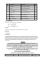
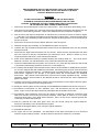
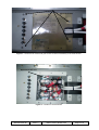
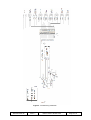
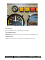
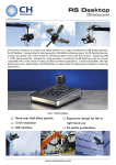
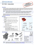
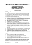
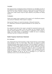
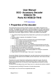
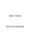
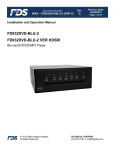
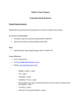
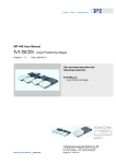
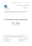
SB-GA8-2012-85
Issue 1
OPTIONAL
PO Box 881, Morwell, Victoria 3840, Australia
Ph + 61 (0) 3 5172 1200
Fax + 61 (0) 3 5172 1201
www.gippsaero.com
Service Bulletin
Subject:
Modifications required for aircraft to be registered in Malaysia
Applicability:
This Service Bulletin applies only to aircraft intended for registration in Malaysia
Amendments:
Nil (initial issue).
Background:
The Department of Civil Aviation Malaysia (DCA) mandates requirements for aircraft to be registered
in that country. The GA8 requires minor modification to ensure compliance with Airworthiness Notices
of Malaysia.
This Service Bulletin describes the installation of an additional caution light in the ignition circuit. If the
starter system of a particular aircraft is deemed non-compliant with Section 3 (c) of Notice 33, then the
following instructions are to be complied with.
Compliance:
Implementation of this bulletin is optional for any GA8 or GA8-TC320 prior to registration in Malaysia.
Weight and Balance:
Negligible effect on weight and balance.
Approval:
This modification has been approved pursuant to Regulation 21.095 of CASR(1998).
Parts:
Item
Part Number
Description
1
A0163C (APEM)
Warning Light Amber
1
2
A0172 (APEM)
Light Housing
1
3
336 (Chicago Miniature)
Globe Midget Grooved
1
4
M39029/63-368
Crimp Contact Female
2
5
M39029/64-369
Crimp Contact Male
2
SB-GA8-2012-85
Issue: 1
Date of Issue: 05 Mar 2012
Qty
Page 1 of 6
Item
Part Number
Description
Qty
6
RT1.25-4DG
Ring Terminal 4 mm Red
1
7
RT1.25-8
Ring Terminal 8 mm Red
1
8
QC1.25-2.8/.5DG
Terminal, Push on
2
9
M22759/16-22-9
Wire 22AWG ETFE 600V
10
RXEF050
Poly Switch 0.5A
1
11
HSTNW (Alco)
Heat shrink tubing
A/R
12
Refer to Instructions
Flight Instrument Panel
A/R
1
Parts Availability:
New parts can be obtained directly from GippsAero.
Tel.:
+61 3 5172 1200
Fax.:
+61 3 5172 1201
Email: [email protected]
Labour:
4 hours should be allocated to the incorporation of this Service Bulletin.
Warranty:
Not applicable.
Installation:
The standard GA8 electrical wiring system is compliant with Department of Civil Aviation Malaysia
Airworthiness Notice No 33 Issue 2 as there exist 2 starter relays or solenoids in series : one within the
starter motor, the other within the solenoid box of the aircraft. However an additional annunciator light
may be fitted to the aircraft’s flight instrument panel. If the starter system of a particular aircraft is
deemed non-compliant with Section 3 (c) of Notice 33, then the following instructions are to be
complied with.
WARNING:
THE ALTERNATOR EXCITATION CAPACITOR LOCATED IN THE SOLENOID BOX IS A
POTENTIAL HAZARD TO PERSONNEL MAINTAINING THE AIRCRAFT BY VIRTUE OF THE
POTENTIAL FOR INADVERTENT SHORTING OF THE POSITIVE SIDE TO GROUND. THIS
WOULD CAUSE A SIGNIFICANT ARC, WHICH, IF IT CAME INTO CONTACT WITH ANY PART
OF THE BODY, COULD RESULT IN A MINOR BURN OR CAUSE A REFLEX ACTION THAT
MAY SHORT OUT OTHER ELECTRICAL CONNECTIONS.
BEFORE REMOVING THE COVER PANEL TO ACCESS THE UNDERFLOOR AREA IN FRONT
OF THE PILOT’S SEAT, PERFORM THE FOLLOWING ACTION TO ENSURE THAT THE
CAPACITOR CIRCUIT IS DISARMED:
(I) PULL THE 1 A BUS 2 CONTROL BREAKER
(II) SWITCH THE BUS 2 MASTER SWITCH ON
ENSURE THAT THE BREAKER REMAINS OPEN AND THE MASTER
SB-GA8-2012-85
Issue: 1
Date of Issue: 05 Mar 2012
Page 2 of 6
SWITCH REMAINS ON FOR THE DURATION THAT THE COVER PANEL
IS REMOVED. NOTE THAT BUS 2 IS NOT LIVE WHILST THE BUS 2
CONTROL BREAKER IS PULLED.
WARNING:
DO NOT PERFORM ANY MAINTENANCE ON THE ELECTRICAL
SYSTEM IN CONJUNCTION WITH MAINTENANCE ON THE FUEL
SYSTEM. THE ESCAPE OF FUEL FUMES UNDER THE FLOOR AND/OR
IN THE AIRCRAFT MAY CAUSE AN EXPLOSION.
1. Remove the pilot seat and gain access to the solenoid box. Take off the fibre glass battery cover.
2. Gain access to the battery box. Disconnect the positive terminal connected to the battery from the
aircraft as a precautionary measure. Refer to the GA8 Service Manual Section Chapter 24.
3. Gain access to the internal components of solenoid box by removal of screws as noted in Figure
1. Take care not to damage the heads of the screws when undoing them. Remove the fibre glass
sheet. Refer to the GA8 Service Manual Section Chapter 24 taking specific note of the warning in
Section 24-00-00.
4. Disconnect circuit PS1A2 from the Starter Solenoid. Refer to Figure 2.
5. Fabricate a single wire assembly, circuit WM1A22 as shown in Figure 3.
6. Combine the ring terminals associated with circuits PS1A2 and WM1A22 back onto the solenoid
electrical terminal.
7. Disconnect the flight instrument panel from the aircraft. Ensure that the exposed pitot and static
lines are covered to prevent contaminants from entering the lines. Refer to Section 31-10-10
“Flight Instrument Sub Panel” of the GA8 Service Manual
8. Route circuit WM1A22 towards the firewall following the existing cable run. This circuit will be
added to connector J41 and fitted with a crimp contact and inserted into position 1.
9. Install circuit WM1D22N into pin position 2 of connector J41. Earth the ring terminal to the aircraft
in accordance with bonding practices noted in AC 21-99 Chapter 13
10. It is unlikely that the flight instrument panel will be able to accommodate an additional annunciator.
For a turbo charged GA8 with traditional instruments, the blanking plug may be removed and the
hole used for the Start annunciator. The blanking plug is located between ALT and the Pitot Heat
annunciators. GippsAero can provide a new panel which will accommodate the additional
annunciator. Part number GA8-311021-093 will suit most normally aspirated aircraft. Contact
GippsAero with the serial number of the affected aircraft to ensure that the correct replacement
panel is provided.
11. Carefully remove all the instruments, lamps, looms and switches from the flight instrument panel.
This step can be omitted for turbo charged Airvans.
12. Modify the “warning light” loom by inserting circuits WM1B22 and WM1C22 as shown in Figure 3.
13. Re-install the instruments (i.e. ASI, altimeter), loom, and annunciator into the new instrument
panel. Figure 4 shows the flight instrument panel fitted with the START annunciator.
14. Re-install the flight instrument panel into the aircraft connecting all electrical connectors, pitot
static lines and the vacuum line (if previously installed). Refer again to Section 31-10-10 “Flight
Instrument Sub Panel” of the GA8 Service Manual. Item 6 of the service manual specifies the
conducting of a pitot static leak test.
15. Refit the solenoid box with fibre glass cover into the aircraft using the original fasteners.
Reconnect the battery to the aircraft electrical system.
16. Reinstall the fibreglass battery cover using the original fasteners.
17. Reinstall the pilot seat.
18. An engine run is to be undertaken. The illumination of the Start annunciator is to be observed
while the engine is being cranked. The lamp will turn off when the starter key is released.
SB-GA8-2012-85
Issue: 1
Date of Issue: 05 Mar 2012
Page 3 of 6
Remove Screws
Figure 1 : Screws to be removed to gain access to internal assembly of the solenoid box
Disconnect this wire
Figure 2 : Location of circuit PS1A2
SB-GA8-2012-85
Issue: 1
Date of Issue: 05 Mar 2012
Page 4 of 6
Figure 3 : Partial wiring schematic
SB-GA8-2012-85
Issue: 1
Date of Issue: 05 Mar 2012
Page 5 of 6
Figure 4 : Completed Flight Instrument Panel
Documentation:
Update aircraft logbooks to reflect incorporation of this Service Bulletin.
Continuing Airworthiness:
There are no additional continuing airworthiness requirements as part of the implementation of this
Service Bulletin.
Compliance Notice:
Complete the Document Compliance Notice and return to GippsAero by mail, fax or email.
SB-GA8-2012-85
Issue: 1
Date of Issue: 05 Mar 2012
Page 6 of 6
DOCUMENT COMPLIANCE NOTICE
Document:
SB-GA8-2012-85
Issue 1
Aircraft Serial Number:
GA8-______________
Service Bulletin SB-GA8-2012-85 Issue 1 has been incorporated in the above aircraft.
Date: ______________________________________
___________________________________________
Signed
Print Name: _________________________________
Please post or fax this compliance notice to:
GippsAero
Attn: Technical Services
P.O. Box 881
Morwell Victoria 3840
Australia
Fax.:
+61 (3) 5172 1201