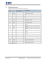
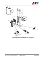
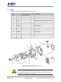
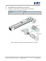
1
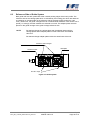
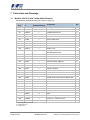
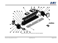
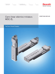
Translation of Original User's Manual Module 160/15 G Edition: June 2011 Article No.: 1102540 IEF Werner GmbH Wendelhofstraße 6 78120 Furtwangen – Germany Phone: + 49 7723 925-0 Fax: +49 7723 925-100 www.IEF-Werner.de [email protected] June 2011 MAN_EN_1102540_Module160-15G_R1a.doc Transl. of Original User's Manual Module 160/15 G Page 1 of 37 Change History: Document Code Date Revision MAN_EN_1102540_Module160-15G_R1a.doc June 2011 Initial release of this English document (originated from German document “MAN_DE_1077858_Modul16015G_R3b.doc”) Trademarks and trade names are used without an assurance of their free usability. Although the texts and examples were created with great thoroughness, errors can not be fully excluded. IEF Werner GmbH does not assume legal responsibility nor any liability for missing or incorrect statements and their consequences. IEF Werner GmbH reserves the right to modify or improve without previous notice the software or hardware or parts of it was well as the supplied documentation or parts of it. IEF Werner GmbH expressly reserves all rights for duplication and photomechanical reproduction, including extracts. We are always grateful for suggestions for improvements and information about errors. © June 2011, IEF Werner GmbH Page 2 of 37 Transl. of Original User's Manual Module 160/15 G June 2011 MAN_EN_1102540_Module160-15G_R1a.doc Contents 1 2 3 Safety 5 1.1 Definition of the Alerts 5 1.2 General Safety Instructions 5 1.3 Special Hazard Warnings 6 Intended Use 7 2.1 Reasonably Foreseeable Misuse 7 Installation Instructions 8 3.1 Installation Position 8 3.2 Overview of Motor Installation Variants 8 3.2.1 Module 160/15 Installation Variant 1 9 3.2.2 Module 160/15 Installation Variant 5 9 3.3 Attachment 10 3.3.1 Installation of Actuators 12 3.4 Wiring 13 3.4.1 Motors 13 3.4.2 Initiators 13 3.4.2.1 Technical Data of Initiators 14 3.4.2.2 Limit Switch 15 3.4.2.3 Collision Switch 15 3.4.3 Cable Routing 15 3.5 Technical Data 16 3.5.1 Tightening Torques for Screw Connections 16 3.5.2 Technical Data of Module 160/15G 16 3.5.3 Type Label 17 3.5.4 Technical Data when Using a Planetary Gearbox 17 3.5.5 Distances between Axes and Number of Teeth 18 3.5.6 Load Cases 19 3.5.6.1 Torques and Carrying Capacities 19 4 Preventive Maintenance 20 5 Troubleshooting 21 6 Repair 23 6.1 Factory Setting of Axial Toothed Belt Tension 24 6.2 Changing the Axial Toothed Belt 24 6.3 Reference Side of Guide System 25 Parts Lists and Drawings 26 7.1 Module 160/15G with Toothed Belt Gearbox 26 7 June 2011 MAN_EN_1102540_Module160-15G_R1a.doc Transl. of Original User's Manual Module 160/15 G Page 3 of 37 8 7.2 Module 160/15G with Direct Drive 28 7.3 Carriage Module 160/15G, Length 195 mm 30 7.4 Toothed Belt Gearbox 32 7.5 Flange 34 7.6 Assemblies/Components Specific to the Version 35 7.6.1 Installation of Flange Gearbox (e.g. Planetary Gearbox Type PLFE64) 35 7.6.2 Overview of Clamping Elements 36 Declaration of Incorporation Page 4 of 37 Transl. of Original User's Manual Module 160/15 G 37 June 2011 MAN_EN_1102540_Module160-15G_R1a.doc 1 Safety 1.1 Definition of the Alerts WARNING Indicates a potentially hazardous situation. Read the warnings before performing the task. CAUTION Indicates a potentially hazardous situation which, if not avoided, could result in minor or moderate injury, damage to equipment or material. Read the cautions before performing the task. NOTE 1.2 Gives additional information. General Safety Instructions The module may be put into operation only by specialist personnel who have received technical safety instructions and can assess potential hazards. In addition, all chapters of the User's Manual have to be read and understood completely. WARNING The system has to be de-energized for all installation, disassembly or repair work. High risk of injuries! WARNING OF HOT SURFACE During operation, the heating of the motor, in particular of stepper motors, can cause the burning of the skin when touching the motor. Install a protective device, if possible! Do not touch the marked areas or only after an adequate cooling time. CAUTION Motor connectors may not be inserted or disconnected under live condition. Risk of burning of the contacts and risk of flying sparks. June 2011 MAN_EN_1102540_Module160-15G_R1a.doc Transl. of Original User's Manual Module 160/15 G Safety Page 5 of 37 CAUTION Linear modules always have to be operated in connection with suitable safety devices (e.g., safety cell, protective room, protective housing, light curtain). NOTE 1.3 Observe the Declaration of Incorporation (see Section Declaration of Incorporation, page 37). Special Hazard Warnings In addition, this User's Manual also contains the following special hazard warning: RISK OF CRUSHING Risk of limb crush injuries during operation at these component positions. Safety Page 6 of 37 Transl. of Original User's Manual Module 160/15 G June 2011 MAN_EN_1102540_Module160-15G_R1a.doc 2 Intended Use The linear drive unit Module 160/15 G (G means ‘Gegenläufig’ = 'in opposing directions’; see Figure 1) was designed for industrial applications. The use of a high-quality guide ensures high dynamics and good running characteristics. The guide elements have special seals which protect them from coarse dirt. However, the application of the linear drive unit Module 160/15G under conditions with increased dirt and abrasive dusts should be avoided because no further protective measures, such as bellow cover, etc., are available. Figure 1: Overview of Module 160/15 G The fields of application for the Module 160/15 G are correspondingly versatile. They range from component insertion systems for SMD components, insertion and pressing-in processes in precision engineering, loading and unloading stations of machine tools to manipulators for the packaging industry. 2.1 Reasonably Foreseeable Misuse The Module 160/15 G is not to be used for certain applications such as the transport of persons and animals or as a pressing/bending device for cold working of metal. The use of the linear module without additional measures is also not possible in special fields of application, such as the chemical or food industry or in explosive atmospheres. In case of doubt, consult the manufacturer. June 2011 MAN_EN_1102540_Module160-15G_R1a.doc Transl. of Original User's Manual Module 160/15 G Intended Use Page 7 of 37 3 3.1 Installation Instructions Installation Position The installation position is optional, i.e. the Module 160/15 G can be installed horizontally as well as vertically. CAUTION For a vertical installation position, use motors with spring-operated brake to prevent the lowering of the drive in de-energized condition! 3.2 Overview of Motor Installation Variants Installation variant 1 Installation variant 2 Installation variant 3 Installation variant 4 Installation variant 5 Installation variant 6 Figure 2: Installation Variants of Module 160/15 G Installation Instructions Page 8 of 37 Transl. of Original User's Manual Module 160/15 G June 2011 MAN_EN_1102540_Module160-15G_R1a.doc 3.2.1 Module 160/15 G Installation Variant 1 L=stroke +424 stroke + 20 + (2 x 195) Mounting measurement A; B; C: stroke limitation limit switch A: Reference point 2 deep (16x) Figure 3: Module 160/15 G subassembly No. 1000477, installation variant 1 3.2.2 Module 160/15 G Installation Variant 5 stroke +424 stroke + 20 + (2 x 195) Mounting measurement A; B; C: stroke limitation limit switch A: Reference point 2 deep (16x) Figure 4: Module 160/15 G subassembly No. 1000477, installation variant 5 June 2011 MAN_EN_1102540_Module160-15G_R1a.doc Transl. of Original User's Manual Module 160/15 G Installation Instructions Page 9 of 37 3.3 Attachment In most applications, the Module 160/15 G is attached with clamping profiles / clamping elements (see Figure 5, below) to a flat assembly surface. The carriage moves freely. Other types of attachment of the linear module, for example with additional drilled holes in the basic profile, should be avoided. In almost all cases, these drilled holes cause tension in the guide basis and the damaging of inner parts of the module. CAUTION The clamping area should have a planeness of 0.1 mm/m². Clamping element Clamping element Figure 5: Crosswise cut with clamping elements and dimensions (Module 160/15) NOTE Installation Instructions Page 10 of 37 For an overview of the different clamping elements, see Section Overview of Clamping Elements, page 36. Transl. of Original User's Manual Module 160/15 G June 2011 MAN_EN_1102540_Module160-15G_R1a.doc RISK OF CRUSHING Risk of limb crush injuries during operation at these component positions. Risk of crushing exists at the start and end of the stroke as well as between both movable carriages (see Figure 6). Figure 6: Potential crushing positions Figure 7 shows the drilling pattern of a standard carriage. 64 ± 0,10 160 16 64 ± 0,10 195 ± 0,10 179 ± 0,10 99 M6 (16x) 12 +0,1 tief(16x) 22 deep (16x) Figure 7: Standard carriage drilling pattern June 2011 MAN_EN_1102540_Module160-15G_R1a.doc Transl. of Original User's Manual Module 160/15 G Installation Instructions Page 11 of 37 Figure 8 shows a centering ring for mounting clamping elements: Figure 8: Centering ring (Art. No. 1024021) With the M6 threaded holes on the carriage, different axis configurations can be achieved, possibly via an adapter plate. The counterbores with 12 mm dia. serve for centering of the clamping elements with possible adjustment. 3.3.1 Installation of Actuators Actuators (gripper modules, cylinders) attached to the linear module are normally attached via the drilling pattern on the carriage (Figure 7, Page 11) to the linear drive unit. Special drilling pattern available on request. Installation Instructions Page 12 of 37 Transl. of Original User's Manual Module 160/15 G June 2011 MAN_EN_1102540_Module160-15G_R1a.doc 3.4 Wiring 3.4.1 Motors CAUTION The electrical connection of the motors is performed according to the motor data sheet. For customer-specific motors, the data sheet must be requested from the respective manufacturer and the motor connected accordingly. 3.4.2 Initiators Inductive proximity switches (PNP-NC, Article No.: 025165; see Figure 9) are used as standard limit switches for the distance traveled as well as for collision protection. These switches are not safety limit switches according to EN60204-1. Optionally, an additional reference point switch (PNP-NO, Article No.: 726744; see Figure 10), can also be retrofitted in the Module 160/15 G. The active switch area is marked with a colored circle symbol. The NCs have a green dot, the NOs have a red dot. The initiators and their supply lines are protected in a cable duct which is integrated in the basic profile and are routed jointly to a connector. A plastic strip serves to cover the cable duct. The replacement of an initiator or its shifting is easily possible after removal of this plastic strip from the cable duct. brown +24VDC black Signal blue 0V Figure 9: Connection assignment PNP-NC, Art. 025165 brown + 24VDC black Signal blue 0V Figure 10: Connection assignment PNP-NO, Art. 726744 June 2011 MAN_EN_1102540_Module160-15G_R1a.doc Transl. of Original User's Manual Module 160/15 G Installation Instructions Page 13 of 37 4 9.9 1 M4 20 40 5 aktive activeFläche area Figure 11: Dimensional sketch of inductive proximity switch 3.4.2.1 Technical Data of Initiators Parameter Value Operating voltage including ripple (10 ... 30) VDC 15% Current load capacity Ia 200 mA Voltage drop at Ia max. 2.5 V Switching frequency 1000 Hz Self current consumption 15 mA Nominal operating distance on steel 2.0 mm 10% Switch hysteresis (3 ... 20) % Reproducibility (U = const.) 0.01 mm Operating temperature - 25 C ... + 70 C Protection class IP 65 Short-circuit proof yes Protected against polarity reversal yes Figure 12: Technical data of initiators Installation Instructions Page 14 of 37 Transl. of Original User's Manual Module 160/15 G June 2011 MAN_EN_1102540_Module160-15G_R1a.doc 3.4.2.2 Limit Switch The pin assignment of the limit switch is as follows (see Figure 13): Pin No. Assignment IEF Werner cable 1 + 24V Brown 2 Limit switch, negative direction of movement, carriage 1 Green 3 0V White 4 Limit switch, negative direction of movement, carriage 2 Yellow 5 Reference switch (optional) Gray Figure 13: Pin assignment of limit switch 3.4.2.3 Collision Switch The collision switch is located on one of the movable carriages. This switch is supplied with open cable end. The switch signal of the collision switch must be wired on both carriages as function "Limit switch of positive direction of movement". 3.4.3 Cable Routing Suitable cable routing has to be used for all moving cables to effectively prevent cable breaks. The minimum radius rmin for cable routing chains is calculated for IEF Werner cables according to the following formula: rmin 10 x cable diameter When different cables are used, EN 60204 must be observed. In addition, it must be ensured that a space reserve of 30% is kept free within the routing chains. A strain relief for the cables has to be attached at the outlet of the cable routing chain. We recommend to also order cables and cable routing chains at IEF Werner GmbH. June 2011 MAN_EN_1102540_Module160-15G_R1a.doc Transl. of Original User's Manual Module 160/15 G Installation Instructions Page 15 of 37 3.5 Technical Data 3.5.1 Tightening Torques for Screw Connections Screw 8.8 Tightening torque [Nm] M3 1.1 M4 2.5 M5 5.0 M6 8.5 M8 21.0 M10 41.0 M12 71.0 Screw 12.9 Tightening torque [Nm] M4 (attachment of guide rail) 3.5.2 4.9 Technical Data of Module 160/15G Parameter Value Repetition accuracy 0.05 mm Weight (without motor) 14 kg Weight increase per 100 mm stroke 1.4 kg Maximum movement speed 5 m/s Maximum acceleration 40 m/s² Maximum transferable feed force with maximum movement speed (5 m/s) 810 N Torque Mx (see Figure 17, page 19) 100 Nm Torque My (see Figure 17, page 19) 100 Nm Torque Mz (see Figure 17, page 19) 100 Nm Carrying capacity C1 (see Figure 17, page 19) 1500 N Carrying capacity C2 (see Figure 17, page 19) 800 N Geometrical moment of inertia of profile cross-section at center of gravity: Ix = 1196016 mm4 Iy = 8689482 mm4 Figure 14: Technical data Installation Instructions Page 16 of 37 Transl. of Original User's Manual Module 160/15 G June 2011 MAN_EN_1102540_Module160-15G_R1a.doc 3.5.3 Type Label Figure 15: Type label (example) 3.5.4 Technical Data when Using a Planetary Gearbox Before start-up, pay attention to the possible input speeds specified by the gearbox manufacturers. Excessive input speeds could cause higher gearbox wear and / or thermal problems. The precision of the linear drive unit is influenced by the play on reversal of the gearbox. Example: The play on reversal of the gearbox (P) is 9 angular minutes. What is the play on reversal at the carriage of the linear drive unit? Feed constant of linear drive unit (Fc): 140 mm Play on reversal at the carriage = = (Fc • P) / (360 x 60) = (140 mm • 9) / (360 x 60) 0.058 mm By all means, pay attention to the specifications of the respective gearbox manufacturer. For example: http://www.neugart.de/index.php/de/Produkte/Standardgetriebe http://www.wittenstein-alpha.de/896.htm June 2011 MAN_EN_1102540_Module160-15G_R1a.doc Transl. of Original User's Manual Module 160/15 G Installation Instructions Page 17 of 37 3.5.5 Distances between Axes and Number of Teeth AA 218,88 Z1 38,88 Z2 Figure 16: Explanation of the table of distances between axes, subassembly No.: 1000475 Maintain the following distances between axes for the specified standard gear ratios: The gearbox toothed belt tension (motor installation variants 1-6, see Figure 2, page 8) is 150 N. i Z1 output 1:1 42 Z2 drive Drilled hole drive Length of toothed belt AA [mm] Feed constant [mm] 42 max. Ø 32 mm 450 mm 120 140 2.1 : 1 42 20 max. Ø 16 mm 390 mm 116.18 66.667 2.625 : 1 42 16 max. Ø 14 mm 390 mm 120.73 53.33 3:1 42 14 max. Ø 12 mm 375 mm 115.35 46.667 Installation Instructions Page 18 of 37 Transl. of Original User's Manual Module 160/15 G June 2011 MAN_EN_1102540_Module160-15G_R1a.doc 3.5.6 Load Cases 3.5.6.1 Torques and Carrying Capacities Figure 17: Torques and carrying capacities Extract from technical data (Figure 14, page 16): Parameter Value Torque Mx 100 Nm Torque My 100 Nm Torque Mz 100 Nm Carrying capacity C1 1500 N Carrying capacity C2 800 N Figure 18: Table of torques and carrying capacities June 2011 MAN_EN_1102540_Module160-15G_R1a.doc Transl. of Original User's Manual Module 160/15 G Installation Instructions Page 19 of 37 4 Preventive Maintenance During the design of Module 160/15 G, great importance was placed on the use of maintenance-free components. All roller elements are provided with lifetime lubrication in the factory. The guide carriages are equipped with auxiliary lubrication elements. An operating performance of 10000 km is therefore achieved with the initial lubrication. In single-shift operation with a stroke of 500 mm and 20 cycles per minute, this is equivalent to an operating performance of almost 5 years. After reaching the specified operating performance, the guide carriage can be relubricated with a special grease gun (IEF Werner Art. No.: 1055123) (see Figure 19). The grease gun is filled with high-performance lubricant Dynalub. One side of the carriage unit has a funnel-shaped lubrication nipple. External lubrication by means of the hand-held grease gun can be performed directly at the carriage. On the opposite side, the toothed belt must be released for lubrication of the guide carriages to access the grease nipples of the guide carriages. NOTE Do no use grease containing ester oils. Figure 19: Lubrication of the guide carriage Preventive Maintenance Page 20 of 37 Transl. of Original User's Manual Module 160/15 G June 2011 MAN_EN_1102540_Module160-15G_R1a.doc 5 Troubleshooting Malfunction Cause Correction Increased running noise Nominal service life of guide carriages exceeded Replace all guide carriages. Guide carriages worn by overload Replace all guide carriages, (excessive torques, etc.) reduce load. Guide carriages worn by excessive soiling Replace all guide carriages, clean guide rails more frequently and relubricate guide carriage. Guide rails worn Replace guide rails, replace all guide carriages, check load, protect linear module from excessive soiling. Guide rails corroded Replace guide rails, replace guide carriages as required. Reversing unit worn Replace reversing unit. Drive unit worn Replace drive unit. Toothed belt runs dry Lightly grease toothed belt on the toothed inner side. Excessive toothed belt tension Readjust toothed belt tension on carriage part. Toothed belt runs canted Align toothed belt on fastener (pressure piece and gear segment), evenly tighten M6 fillister head screws! Heavy soiling of toothed belt on Replace toothed belt, protect linear module from the toothed inner side heavy soiling. Toothed belt damaged Replace toothed belt. Motor (motor bearing) damaged Replace motor. Motor with brake, brake does not release Linear drive unit Limit switch cable not does not move connected Apply current to the brake, if the brake still does not release, replace motor. Connect the cable. Limit switch, collision switch defective Replace limit switch, collision switch. Limit switch cable damaged Check limit switch cable. Soldered connection on socket became loose Solder wires. Incorrect motor connection Check and change connector assignment, if required. Motor damaged Replace motor. June 2011 MAN_EN_1102540_Module160-15G_R1a.doc Transl. of Original User's Manual Module 160/15 G Troubleshooting Page 21 of 37 Continuation of troubleshooting: Malfunction Cause Correction Linear drive unit Error in power electronics or does not move control unit Motor cable damaged Check the power electronics or the control unit. Check motor cable, replace cable, if required. Belt transmission: Toothed disk Firmly tighten clamping set and secure screws slips with safety lacquer. Planetary gearbox: Coupling between motor and planetary gearbox slips Firmly tighten coupling and secure screws with safety lacquer. Motor with brake, brake does not release Apply current to the brake, if the brake still does not release, replace motor. Play on reversal Gearbox toothed belt not tensioned Toothed disk of motor has play (parallel key connection) Replace toothed disk of motor and, if the parallel key groove of the motor is damaged, replace motor. Drive tooth belt without adequate pre-tension Tension drive tooth belt. Linear drive unit Incorrect direction of rotation moves Broken motor cable mechanically against the stop during the reference run Troubleshooting Page 22 of 37 Tension gearbox toothed belt. Change motor direction of rotation. Replace cable. Transl. of Original User's Manual Module 160/15 G June 2011 MAN_EN_1102540_Module160-15G_R1a.doc 6 Repair WARNING Always de-energize the system before beginning the repair. WARNING Generally, repairs must be performed by specialist personnel who have read and understood the User’s Manual. CAUTION Only when original parts are used can warranty claims be accepted by IEF Werner GmbH. June 2011 MAN_EN_1102540_Module160-15G_R1a.doc Transl. of Original User's Manual Module 160/15 G Repair Page 23 of 37 6.1 Factory Setting of Axial Toothed Belt Tension The toothed belt tension of the axial toothed belt is set with adjusting screws (see Figure 20). When delivered, the toothed belt tension is correct and the adjusting screws are secured in position with safety lacquer. Adjusting screws Figure 20: Adjusting screws for belt tension NOTE Do not remove the safety lacquer at the adjusting screws. The gearbox toothed belt tension (motor installation variants 1-6, see Figure 2, page 8) is 150 N. 6.2 Changing the Axial Toothed Belt For explanation, see Figure 22, page 27 and Figure 24, page 31. To change the axial toothed belt, proceed as follows: Figure 24, page 31: Loosen the screws M6 x 35 (pos.100), remove pressure piece (Pos. 40), remove toothed quadrant (Pos. 30). Figure 22, page 27: remove plastic covers (Pos.100). Remove defective toothed belt, install new toothed belt. Insert toothed belt in the middle of toothed quadrant (Pos. 30) and pressure piece (Pos. 40). The pressure piece and the toothed quadrant can be wrapped with a thin adhesive tape. This makes it easier to insert these parts into the carriage. Tension the pressure piece with screws M6 x 35 (pos.100) on "block". Belt tension adjusted in factory: Do not remove the safety lacquer on the screws (pos. 120, Figure 24, page 31)! Re-install plastic covers (pos.100, Figure 22, page 27). Repair Page 24 of 37 Transl. of Original User's Manual Module 160/15 G June 2011 MAN_EN_1102540_Module160-15G_R1a.doc 6.3 Reference Side of Guide System Both guide rails are each positioned at the outward pointing edges of the basic profile. The reference side of the carriage plate which is indicated by two locating pins which are attached one-sided is on the same side as the reference side of the basic profile (marked by a 90° notch). When new, the guide carriages have an increased slide resistance. After a short run-in period (1 to 2 days), the slide resistance is reduced to normal. The adapter plates are each placed on the guide carriage at the guide carriage reference side. NOTE Do not interchange the carriage plate and the adapter plates with the carriage plates and/or adapter plates of other linear drive units Module 160/15 G! Do not interchange adapter plates within the same linear drive unit! Reference side carriages Slide plate Reference mark Put rail to edge Figure 21: Guide system June 2011 MAN_EN_1102540_Module160-15G_R1a.doc Transl. of Original User's Manual Module 160/15 G Repair Page 25 of 37 7 Parts Lists and Drawings 7.1 Module 160/15 G with Toothed Belt Gearbox Subassembly 1000588 (drawing see Figure 22, page 27) Drawing Article Pos. No. Part (1)/ Designation Subassembly (0) E/V 10 1000478 0 Basic profile 160/15 20 1000688 0 Ball rail guide, type 15 V 30 1061034 1 Toothed belt 32ATL5 V 40 626061 1 Fillister head screw DIN 912-M4x16-12.9 50 1023994 1 Groove slide block L=70mm 60 731466 1 Groove slide block 70 1025262 1 Housing with damper 80 626037 1 Fillister head screw DIN 912 - M6x20-8.8 90 627581 1 Cylindrical pin ISO 8734-5m6x20-A 100 1034373 1 Plastic cover 110 626124 1 Hexagon socket head countersunk screw ISO 10642-M4x10-8.8 120 1045543 1 Shim DIN 988-36x45x0.1 130 1019278 1 Bearing cover 140 028585 1 Limit switch holder 150 025165 1 Inductive switch, PNP-NC E 160 726744 1 Inductive switch, PNP-NO E 170 030887 1 Special screw M4x7 180 725164 1 Angular coupling 190 725163 1 Round plug 200 025626 1 Retaining sheet metal 210 627630 1 Oval head screw ISO 7380-M3x8-8.8 220 626056 1 Fillister head screw DIN 912-M6x16-8.8 230 1044440 1 Plastic clip 240 1018820 1 Drive unit 160/15/32 V “ 1077831 1 Drive unit 80/15/32/FLG V 250 1042984 1 Pulley V 260 1018827 1 Stop + 270 1056053 1 Carriage unit 160/15 G L=195mm V --- 1000041 0 Motor V 290 1000475 0 Toothed belt gearbox V 330 1024065 1 Switch rail - collision switch 340 1024068 1 Distance washer + = usage depending on version E = replacement part V = wearing part Parts Lists and Drawings Page 26 of 37 Transl. of Original User's Manual Module 160/15 G June 2011 MAN_EN_1102540_Module160-15G_R1a.doc stop for stroke limitation Figure 22: Linear drive unit 160/15 G with toothed belt gearbox June 2011 MAN_EN_1102540_Module160-15G_R1a.doc Transl. of Original User's Manual Module 160/15 G Parts Lists and Drawings Page 27 of 37 7.2 Module 160/15 G with Direct Drive Subassembly 1000588 (drawing see Figure 23, page 29) Drawing Article Pos. No. Part (1)/ Designation Subassembly (0) E/V 10 1000478 0 Basic profile 160/15 20 1000688 0 Ball rail guide, type 15 V 30 1061034 1 Toothed belt 32ATL5 V 40 626061 1 Fillister head screw DIN 912-M4x16-12.9 50 1023994 1 Groove slide block L=70mm 60 731466 1 Groove slide block 70 1025262 1 Housing with damper 80 626037 1 Fillister head screw DIN 912 - M6x20-8.8 90 627581 1 Cylindrical pin ISO 8734-5m6x20-A 100 1034373 1 Plastic cover 110 626124 1 Hexagon socket head countersunk screw ISO 10642-M4x10-8.8 120 1045543 1 Shim DIN 988-36x45x0.1 130 1019278 1 Bearing cover 140 028585 1 Limit switch holder 150 025165 1 Inductive switch, PNP-NC E 160 726744 1 Inductive switch, PNP-NO E 170 030887 1 Special screw M4x7 180 725164 1 Angular coupling 190 725163 1 Round plug 200 025626 1 Retaining sheet metal 210 627630 1 Oval head screw ISO 7380-M3x8-8.8 220 626056 1 Fillister head screw DIN 912-M6x16-8.8 230 1044440 1 Plastic clip 240 1018820 1 Drive unit V “ 1077831 1 Standard drive unit V 250 1042984 1 Pulley V 260 1018827 1 Stop + 270 1056053 1 Carriage unit 160/15 G L=195mm V 280 1000041 0 Motor V 290 1000886 0 Planetary gearbox V 310 1050247 1 Flange --- 626049 1 Fillister head screw DIN 912-M6x35-8.8 --- 626061 330 1024065 1 Switch rail - collision switch 340 1024068 1 Distance washer Fillister head screw DIN 912-M4x16-8.8 + = usage depending on version E = replacement part V = wearing part Parts Lists and Drawings Page 28 of 37 Transl. of Original User's Manual Module 160/15 G June 2011 MAN_EN_1102540_Module160-15G_R1a.doc stop for stroke limitation Figure 23: Linear drive unit 160/15 G with direct drive June 2011 MAN_EN_1102540_Module160-15G_R1a.doc Transl. of Original User's Manual Module 160/15 G Parts Lists and Drawings Page 29 of 37 7.3 Carriage Module 160/15 G, Length 195 mm Article No.: 1056053 (drawing see Figure 24, page 31) Drawing Article Pos. No. Part (1)/ Designation Subassembly (0) E/V 10 1029382 1 Guide carriage, size 15 V 20 1046583 1 Guide carriage size 15, for external lubrication V 30 1059202 1 Toothed quadrant 40 1023935 1 Pressure piece 50 1041818 1 Adapter plate 60 1056056 1 Carriage plate 160/15 G 70 1023944 1 Cover 80 626484 1 Fillister head screw DIN 912-M4 x 25-8.8 90 626500 1 Fillister head screw DIN 912-M6 x 18-8.8 100 626049 1 Fillister head screw DIN 912-M6 x 35-8.8 110 626115 1 Hexagon socket head countersunk screw DIN 7991 M3 x 8 120 626190 1 Threaded pin DIN 913-M6 x 10-8.8 130 1023942 1 Threaded bush 140 626317 1 Cylindrical pin ISO 8734-4x20-A 150 1031602 1 O-ring, type 1,80 – 1,80 160 1028704 1 Funnel-shaped grease nipple, DIN 3405, type D4 170 1062938 1 Adapter plate 160/15 G 180 626487 1 Fillister head screw DIN 912-M5 x 10-8.8 E E = replacement part V = wearing part Parts Lists and Drawings Page 30 of 37 Transl. of Original User's Manual Module 160/15 G June 2011 MAN_EN_1102540_Module160-15G_R1a.doc Figure 24: Carriage 160/15 G, exploded view June 2011 MAN_EN_1102540_Module160-15G_R1a.doc Transl. of Original User's Manual Module 160/15 G Parts Lists and Drawings Page 31 of 37 7.4 Toothed Belt Gearbox Subassembly 1000475 (drawing see Figure 25, page 33) Drawing Article Pos. No. Part (1)/ Subassembly (0) Use Designation 10 1021557 1 Housing 20 029690 1 Toothed disk AT5/42-0 30 1007376 1 + Toothed disk AT5/42-2 40 028722 1 + Toothed disk AT5/42-2 50 1006664 1 + Toothed disk AT5/42-2 60 732770 1 70 732770 1 + Clamping set 16/32 80 732294 1 + Clamping set 20/38 90 734168 1 + Clamping set 22/40 95 526735 1 + Toothed disk AT5/20-2 including clamping set 12 98 525983 1 + Toothed disk AT5/20-2 including clamping set 14 100 525984 1 + Toothed disk AT5/20-2 including clamping set 16 110 1005790 1 + Toothed disk AT5/14-2 including clamping set 10 120 1005756 1 + Toothed disk AT5/14-2 including clamping set 12 130 1003999 1 Belt transmission cover 140 028574 1 Gliding block 150 626072 1 Oval head screw ISO 7380-M4 x 8-8.8 160 1004001 1 Push-in cover 170 730353 1 + Toothed belt 25AT5/390 180 732286 1 + Toothed belt 25AT5/375 190 908243 1 + Toothed belt 25AT5/450 Clamping set 16/32 + = usage depending on version Parts Lists and Drawings Page 32 of 37 Transl. of Original User's Manual Module 160/15 G June 2011 MAN_EN_1102540_Module160-15G_R1a.doc 150 130 160 10 140 20 170 / 180 / 190 60 130 150 i 3:1 i 2,1:1 110 / 120 i 1:1 95 / 98 / 100 30 / 40 / 50 70 / 80 / 90 Figure 25: Belt transmission of Module 160/15, exploded view June 2011 Transl. of Original User's Manual Module 160/15 G MAN_EN_1102540_Module160-15G_R1a.doc Parts Lists and Drawings Page 33 of 37 7.5 Flange Subassembly 1000476 (drawing see Figure 26, below) Drawing Article Pos. No. Part (1)/ Subassembly (0) Use Designation 10 1022105 1 Flange, axial 20 1022129 1 Flange plate, axial 30 734161 1 Plastic cover 40 626037 1 Fillister head screw DIN 912-M6 x 20-8.8 50 626244 1 Fillister head screw DIN 912-M6 x 60-8.8 60 627215 1 Locking ring DIN 472-47-1.75 70 1022199 1 75 1022203 1 80 1022201 1 + Coupling dia.=20 90 1022202 1 + Coupling dia.=22 100 1006530 1 + Sleeve 12/16 110 1007310 1 + Sleeve 15/20 120 1008886 1 + Sleeve 14/16 130 1022206 1 + Sleeve 19/22 + Coupling dia.=16 Toothed ring red + = usage depending on version 30 10 20 60 50 40 100 / 110 / 120 / 130 70 / 80 / 90 75 70 Figure 26: Flange Module 160/15, i = 1:1 CAUTION Also please pay attention to the list of parts subject to wear specific to the order which is enclosed with the delivery. Parts Lists and Drawings Page 34 of 37 Transl. of Original User's Manual Module 160/15 G June 2011 MAN_EN_1102540_Module160-15G_R1a.doc 7.6 Assemblies/Components Specific to the Version 7.6.1 Installation of Flange Gearbox (e.g. Planetary Gearbox Type PLFE64) The following drive unit for flange gearboxes is used: Description Part No. Drive unit 80/15/32/FLG 1077831 Drive unit Flange Flangegearbox gearbox Figure 27: Installation of flange gearbox (example with drive unit 1077831) June 2011 Transl. of Original User's Manual Module 160/15 G MAN_EN_1102540_Module160-15G_R1a.doc Parts Lists and Drawings Page 35 of 37 7.6.2 Overview of Clamping Elements counterbore Clamping element, example: type 105 Dimensional drawing of clamping element Clamping element type: L1 in mm L2 in mm 16 0 16 220701 65 49 65 1062169 80 64 80 1021641 105 89 105 28674 115 99 115 1054491 140 124 140 220702 160 64 160 1039032 Customer-specific 1019192 Undrilled Article number: 8 8 8 L1 8 8 8 8 8 8 8 8 8 L L2 L2 L1 L2 L1 L1 L2 L2 L1 8 L1 8 8 Typ 16 L2 L1 L2 8 8 8 Typ 65 T yp 105 8 8 Typ 80 Typ 115 Typ 140 Typ 160 SpannprofilL=customer-specific L = k undenspezifisch Clamping element Figure 28: Overview of clamping elements Parts Lists and Drawings Page 36 of 37 Transl. of Original User's Manual Module 160/15 G June 2011 MAN_EN_1102540_Module160-15G_R1a.doc 8 Declaration of Incorporation EC Declaration of Incorporation in accordance with the EC Directive 2006/42/EC (Machinery), Annex II B We, the manufacturer: IEF Werner GmbH Wendelhofstraße 6 78120 Furtwangen - Germany hereby declare that the following product (the incomplete machine / partly completed machine): Designation IEF Werner subassembly number Module 160/15 G (operating in opposing directions) TG1000588 complies with all essential requirements of Directive Machinery (2006/42/EC), as far as the scope of delivery allows: Annex I, Article: 1.1.2; 1.1.3; 1.1.5; 1.3.2; 1.3.4; 1.5.1; 1.7.3. In addition, the partly completed machinery is in conformity with the following Directives: Directive 2004/108/EC of the Council of 15 December 2004 on the approximation of the laws of the Member States relating to electromagnetic compatibility. Directive 2006/95/EG of the Council of 12 December 2006 on the approximation of the laws of the Member States relating to electrical equipment designed for use within certain voltage limits. The technical documentation is compiled in accordance with Annex VII Part B and can be transmitted, in response to a reasoned request by the appropriate national authorities, in electronic form. List of some harmonized standards used: EN ISO 12100-1,-2 / EN ISO 13857 / EN ISO 13850 / EN 60204 -1 The incomplete machine supplied by us must not be put into service until the final machine into which the incomplete machinery is to be incorporated has been declared in conformity with the fundamental safety and health requirements according to Annex I of EC Directive 2006/42/EC referred to above. Name of person responsible for documentation: Frank Reichelt, Technical Writer Address of person responsible for documentation: See Manufacturer's address Furtwangen, 21 June 2011 June 2011 Manfre d Bär (Managing Director) Transl. of Original User's Manual Module 160/15 G MAN_EN_1102540_Module160-15G_R1a.doc Declaration of Incorporation Page 37 of 37