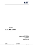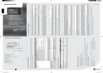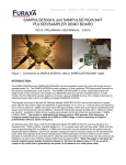
1
Translation of the original instructions Module 105(S)/142(S) Issue: April 2013 Article no.: 1040573 IEF Werner GmbH Wendelhofstraße 6 78120 Furtwangen - Germany Phone: + 49 7723-925-0 Fax: + 49 7723-925-100 www.IEF-Werner.de April 2013 MAN_EN_1040573_Modul105-142_R2b.doc Translation of the original instructions Modul 105(S)/142(S) Page 1 of 43 Change History: Document code Date Revision MAN_EN_1040573_Modul105_142_R1a.doc May 2006 Release of the English document MAN_EN_1040573_Modul105_142_R2a.doc February 2007 Changes to the couplings for parallel drive Document updated regarding the new machinery directive (MRL 2006/42/EC) MAN_EN_1040573_Modul105_142_R2b.doc April 2013 Translation from German Document: “MAN_DE_1040545_Modul105_142_R4a.doc” Formal changes Trademarks and trade names are used without any warranty of their free usability Texts and examples were created with great care. Nevertheless, errors cannot be excluded. IEF Werner GmbH does not assume legal responsibility nor any liability for missing or incorrect statements and their consequences. IEF Werner GmbH reserves the right to modify or improve the software or hardware or parts of it, as well as the supplied documentation or parts of it, without previous notice. IEF Werner GmbH expressly reserves all rights for replication and photomechanical reproduction, including in extracts. We are always grateful for suggestions for improvements and information about errors. © April 2013, IEF Werner GmbH Page 2 of 43 Translation of the original instructions Modul 105(S)/142(S) April 2013 MAN_EN_1040573_Modul105-142_R2b.doc Table of Contents 1 2 3 Safety 5 1.1 Definition or warning notes 5 1.2 General warning notes 5 1.3 Special hazard warnings 6 Intended use 7 2.1 7 Reasonably foreseeable misuse Assembly instructions 8 3.1 Installation position 8 3.2 Module attachment 8 3.3 Installation of actuators 11 3.4 Wiring 12 3.4.1 Motors 12 3.4.2 Initiators 12 3.4.2.1 3.4.3 3.5 Technical data of the limit switches 13 Cable routing 14 Technical data 15 3.5.1 Critical spindle speed 16 3.5.2 Type label 16 3.5.3 Technical data when using a planetary gear 17 4 Maintenance 18 5 Troubleshooting 19 6 Repair instructions 21 6.1 Module 105 and Module 142 21 6.1.1 Replacement of the linear bearings 21 6.1.2 Replacement of the deflection unit 23 6.1.3 Motor replacement module 105 24 6.1.4 Replace gear toothed belt module 105 26 6.1.5 Motor replacement module 142 27 6.1.6 Replace gear toothed belt module 142 27 6.1.7 Replacing the initiator 28 6.1.8 Replacing the drive toothed belt 28 6.1.9 Replacing drive set module 105 29 6.1.10 Replacing drive set module 142 30 Module 105 S and Module 142 S 32 6.2 April 2013 MAN_EN_1040573_Modul105-142_R2b.doc Translation of the original instructions Modul 105(S)/142(S) Page 3 of 43 6.3 7 8 6.2.1 Replacing the cover belt 32 6.2.2 Replace end-plate-side spindle bearing 33 6.2.3 Replacement of linear bearing 34 6.2.4 Replace motor 34 6.2.5 Replace coupling (version 1: stiff coupling) 35 6.2.6 Replace coupling (version 2: Elastomer coupling) 36 6.2.7 Replacing the initiator 36 6.2.8 Replacement of spindle 37 Module 105 and module 142 parallel drive 39 6.3.1 Replace shaft coupling connection shaft 39 6.3.2 Replacing the slave drive set 40 Replacement, wear parts 41 7.1 Module 105 41 7.2 Module 105 S 41 7.3 Module 142 42 7.4 Module 142 S 42 Declaration of incorporation Page 4 of 43 Translation of the original instructions Modul 105(S)/142(S) 43 April 2013 MAN_EN_1040573_Modul105-142_R2b.doc 1 Safety 1.1 Definition or warning notes WARNING Indicates potential danger. Non-observance of the safety provisions may cause death or severe injury. CAUTION Indicates potential danger. Non-observance of the safety provisions may cause property damage or injury. NOTE 1.2 Offers additional information. General warning notes The module must only be commissioned by specialists who received safety-technical instruction and are able to assess potential dangers. Furthermore, all chapters of these operating instructions must have been read and understood completely. WARNING The system must be powered down for all assembly, disassembly or repair work. There is a high danger of injury. WARNING OF HOT SURFACE During operation, heating of the motor, in particular of stepper motors, can cause burns of the skin when touching the motor. Install a protective device, if possible! Do not touch the marked areas or wait for an adequate cooling time. CAUTION Motor connectors must not be inserted or disconnected when live. Risk of burning of the contacts and risk of flying sparks. April 2013 MAN_EN_1040573_Modul105-142_R2b.doc Translation of the original instructions Modul 105(S)/142(S) Safety Page 5 of 43 CAUTION Linear modules always have to be operated in connection with suitable safety devices (e.g., safety cell, protective room, protective housing, light curtain). NOTE 1.3 Observe the Declaration of Incorporation (see section Declaration of incorporation, page 43). Special hazard warnings In addition, this Original User's Manual also contains the following special hazard warning: DANGER FROM CRUSHING These places of the components pose the danger of crushing limbs in operation. Safety Page 6 of 43 Translation of the original instructions Modul 105(S)/142(S) April 2013 MAN_EN_1040573_Modul105-142_R2b.doc 2 Intended use The linear units module 105 and module 142 (see Figure 1) are precise linear adjustment units with circumfering toothed-belt drive. The types module 105 S and module 142 S are equipped with spindle drives (ball roller or trapezoid spindle). All linear units named are used as installation parts in connection with other components in the commercial area. In combination with many standardised installation elements and the other linear modules of IEF Werner GmbH (e.g. module 68, module 68 D, module 142 and module 142 S), complex multi-axis handling systems can be developed as well. Figure 1: Module 142 The areas of use of these linear units are accordingly diverse. They range from: 2.1 Stop adjustment in the wood industry Equipment systems for SMD components Joining and press-in processes in precision mechanics Loading and unloading station of tool machines up to Manipulators for the packaging industry Reasonably foreseeable misuse The linear module M105(S) / M142(S) is not to be used for certain applications, and in particular not for such as the transport of persons and animals or as a pressing/bending device for cold working of metal. Use of the linear units without additional measures is also not possible in special fields of application, such as the chemical or food industry or in explosive atmospheres. In case of doubt, consult the manufacturer. April 2013 Translation of the original instructions Modul 105(S)/142(S) MAN_EN_1040573_Modul105-142_R2b.doc Intended use Page 7 of 43 3 Assembly instructions 3.1 Installation position The installation position is optional, i.e. the linear modules module 105 and module 142 can be used horizontally as well as vertically. CAUTION In the vertical installation position, use only motors with spring-operated brake to prevent the lowering of the drive in de-energized condition! 3.2 Module attachment Use of clamping elements permits assembly-friendly attachment of the linear units module 105 and module 142 on a level installation surface. The drilling distance for installation surface depends on the construction series. For cross installation of the linear units, there are clamping elements in standard lengths that are equipped with the system drill template of the respective construction size (see "Attachment of linear modules" Figure 2 to Figure 9 on pages 8 to 10). For attachment of a linear module on an installation surface, continuous clamping profiles are preferable to clamping elements for safety reasons. This avoids shear points likely to cause accidents. CAUTION The clamping surface should have a levelness of 0.1 mm/m². Do not use attachment bores installed in the basic body, because this may cause damage to internal parts and tension on the guide basis. Hole distance s Figure 2: Attachment of the linear modules with clamping elements/clamping profile Assembly instructions Page 8 of 43 Translation of the original instructions Modul 105(S)/142(S) April 2013 MAN_EN_1040573_Modul105-142_R2b.doc Linear module Hole distance s Thread Module 105 124 mm M6 Module 142 168 mm M8 Figure 3: Scaled drawing clamping element/clamping profile Linear module A B C D Module 105 Module 105 S 24 mm 14.3 mm 7.7 mm 7 mm Module 142 Module 142 S 30 mm 15.5 mm 7.9 mm 7.5 mm Figure 4: Dimensions of the clamping elements or clamping profiles crushing position shear points Figure 5: Attachment of the linear modules with standard clamping elements crushing position Figure 6: Attachment of the linear modules with continuous clamping profiles April 2013 Translation of the original instructions Modul 105(S)/142(S) MAN_EN_1040573_Modul105-142_R2b.doc Assembly instructions Page 9 of 43 Another version is attachment of the linear modules to their carriage. The basic body moves freely. However, the motor, motor, brake and limit switch cables, as well as the encoder or resolver cables have to be moved along. There are special connection screws for this type of attachment (see Figure 8, page 10). Carriage Figure 7: Attachmnet of the linear module to the carriage Module easyLINE, M105, M105S: Modul 68,68, easyLINE, M105, M105S: M6 M6 Modul 142, Modul 142 S: M8S: M8 Module 142, Module 142 Figure 8: Connection screw Linear module A B C Thread (D) Module 105/Module 105 S 124 mm 124 mm 140 mm M6 Module 142/Module 142 S 168 mm 168 mm 190 mm M8 Figure 9: Mounting bores in the carriage Assembly instructions Page 10 of 43 Translation of the original instructions Modul 105(S)/142(S) April 2013 MAN_EN_1040573_Modul105-142_R2b.doc 3.3 Installation of actuators Actuators to be installed on the linear module (pick-up modules, cylinders) are usually attached to the linear unit using the drill template on the carriage (see Figure 9, page 10). If a setup according to Figure 7, page 10 is used, actuators may be attached according to the illustration in Figure 10, page 11 . Only very light-weight attachments (< 1 kg) may also be attached directly to the end plate. In this case, apply the end plate with a suitable drill template. Adapter plate Adapterplatten Adapterplatten S pannelement Spannelement Clamping element T yp 140 (Modul 105) bzw. Typ142) 190 (Modul 142) Typ 140 (Module (Modul 105) 190 (Modul Type 105)bzw. resp.Typ Type 190 (Module 142) Figure 10: Installation example April 2013 Translation of the original instructions Modul 105(S)/142(S) MAN_EN_1040573_Modul105-142_R2b.doc Assembly instructions Page 11 of 43 3.4 Wiring 3.4.1 Motors CAUTION Wire the motors according to the motor data sheet! When using customer-specific motors, inquire at the respective manufacturer for the cable suitable for this motor. 3.4.2 Initiators Inductive proximity switches (PNP normally closed contacts, article number 025165) are used as standard stroke limit switches. These stroke limit switches are not safety limit switches according to EN60204-1. Optionally, an additional reference point switch (PNP-normally open contact. article no. 726744) can be installed. The active button is marked with a coloured circle. Normally closed contacts are marked with a green, normally open contacts with a red dot. The initiators and their supply lines are protected in a cable channel integrated in the basic body, and are centrally wired to a plug. 4 9,9 1 M4 40 20 5 activeFläche area aktive Figure 11: Initiator dimensions Figure 12: Connection designation PNP normally closed contact Assembly instructions Page 12 of 43 Translation of the original instructions Modul 105(S)/142(S) April 2013 MAN_EN_1040573_Modul105-142_R2b.doc Figure 13: Connection designation PNP normally open contact 3.4.2.1 Technical data of the limit switches Parameter Value Operating voltage 10...30 VDC incl. residual ripple 15 % Current load capacity Ia 200 mA Voltage drop at Ia max. 2.5 V Switching frequency 1,000 Hz Own current consumption 15 mA Nominal switching distance on steel 1.5 mm 10 % Switching hysteresis 3...20 % Reproducibility (U = const.) 0.01 mm Operating temperature - 25 ... + 70 C Protection class IP 65 Short-circuit proof yes Protected against polarity reversal yes Pin-no. assignment IEF-cable 1 + 24 V brown 2 limit switch -movement green 3 0V white 4 limit switch +movement yellow 5 Reference switch grey 3 2 4 1 5 Figure 14: Plug assignment April 2013 Translation of the original instructions Modul 105(S)/142(S) MAN_EN_1040573_Modul105-142_R2b.doc Assembly instructions Page 13 of 43 3.4.3 Cable routing For all moving cables, suitable cable routing has to be used to effectively prevent cable breaks. The minimum radius rmin for cable carriers results from the following formula: For IEF cables: rmin 10 x cable diameter. When different cables are used, EN 60204 must be observed. In addition, it must be ensured that a space reserve of 30% is kept free within the routing chains. A strain relief for the cables has to be attached at the outlet of the cable routing chain. Assembly instructions Page 14 of 43 Translation of the original instructions Modul 105(S)/142(S) April 2013 MAN_EN_1040573_Modul105-142_R2b.doc 3.5 Technical data Module 105 Module 105 S Module 142 Module 142 S Repeating accuracy +/- 0.04 mm +/- 0.02 mm +/- 0.04 mm +/- 0.02 mm Weight (without motor) at stroke 0 4.5 kg 6.3 kg 11.2 kg 11.2 kg Weight increase per 100 mm stroke 0.8 kg 1.05 kg 1.25 kg 1.5 kg Maximum movement speed 2 m/s 1 m/s 2 m/s 1 m/s Torque Mx (s. Figure 15) 50 Nm 50 Nm 240 Nm 240 Nm Torque My 70 Nm 70 Nm 230 Nm 230 Nm Torque Mz 35 Nm 35 Nm 110 Nm 110 Nm Carrying capacity C1 1,500 N 1,500 N 3,800 N 3,800 N Carrying capacity C2 700 N 700 N 2,100 N 2,100 N Figure 15: Torques and carrying capacity module 105 and module 142 April 2013 Translation of the original instructions Modul 105(S)/142(S) MAN_EN_1040573_Modul105-142_R2b.doc Assembly instructions Page 15 of 43 3.5.1 Critical spindle speed While the maximum movement speed in linear modules with toothed-belt drive is generally limited by the drive motor, the critical spindle speed in linear modules with spindle drive require observation of the critical spindle speed. It determines the maximum possible movement speed, in particular for longer strokes (see Figure 16, page16) movement speed calculated from the spindle speed according to the following equation: v = n/60 * h v = movement speed [mm/s] n = spindle speed [rpm] h = spindle pitch [mm] Spindle speed[U/min] [U/min] Spindeldrehzahl 2500 2000 1500 1000 500 0 Hub [mm] Stroke [mm] 500 1000 1500 Figure 16: Critical spindle speed 3.5.2 Type label Module 105/142 Figure 17: Type label (example) Assembly instructions Page 16 of 43 Translation of the original instructions Modul 105(S)/142(S) April 2013 MAN_EN_1040573_Modul105-142_R2b.doc 3.5.3 Technical data when using a planetary gear Before commissioning, observe the possible input speeds of the gear manufacturers. Too-high input speeds can lead to increased wear at the gear and/or thermal problems. The accuracy of the linear unit is influenced by the reverse play of the gears. Example: The gear reverse play (S) is 9 angle minutes. How high is the reverse play at the carriage of the linear unit? Infeed constant of the linear unit (Vk): 140 mm Reverse play at the carriage = (Vk • S) / (360 x 60) = (140 mm • 9) / (360 x 60) = 0.058 mm Consider the information of the respective gear manufacturer in any case. e.g. http://www.neugart.de/index.php/de/Produkte/Standardgetriebe http://www.wittenstein-alpha.de/spielarme-planetengetriebe.html April 2013 Translation of the original instructions Modul 105(S)/142(S) MAN_EN_1040573_Modul105-142_R2b.doc Assembly instructions Page 17 of 43 4 Maintenance During the design of the linear module series, great importance was placed on the use of lowmaintenance components. All roller elements were provided with lifetime lubrication in the factory. To avoid danger of over-lubrication of the linear bearings, no external lubrication nipples were attached to the carriage part. However, to achieve a high service life of the wipers, we recommend moistening the guide shafts with special grease at regular intervals. Proceed accordingly when using a ball screw. The lubricant may be procured from IEF in tubes of 50 gram each (special grease for linear bearings: Article no. 732934; special grease for spindles: article no. 729148). If a bellows is used, it should also be regularly cleaned from gross contamination. The recommended maintenance intervals add up to approx. 200 operating hours under regular ambience conditions. Under difficult conditions (high dust share, high humidity, high temperature), the maintenance intervals should be reduced. NOTE Maintenance Page 18 of 43 Never use compressed air for cleaning. Translation of the original instructions Modul 105(S)/142(S) April 2013 MAN_EN_1040573_Modul105-142_R2b.doc 5 Troubleshooting Interference Reason Correction Increased running noise Nominal service life of linear bearing exceeded Replace all linear bearings Linear bearing worn from overload (too-high torque, etc.) Replace all linear bearings, reduce load Linear bearing worn from strong contamination Replace all linear bearings, clean guide elements guide shafts more often if required or use bellows Guide shafts worn Replace guide shafts, replace all linear bearings, check load, protect linear module from strong contamination, use bellows if required Guide shafts corroded Replace guide shafts, replace linear bearing if required, lubricate guide shafts more often Deflection unit worn Replace deflection unit Drive unit worn Replace drive unit Toothed belt runs dry Slightly lubricate toothed belt on the toothed inner side Toothed belt tension too high Install reconciled spacer sleeves as shaft stop Toothed belt runs diagonally Align toothed belt with belt fastener (carriage plate and tappet), install reconciled spacer sleeves Toothed belt strongly contaminated on the toothed inner side Replace toothed belt, protect linear module from strong contamination Toothed belt defective Replace toothed belt Motor (motor bearing) defective Replace motor Motor with brake, brake does not open Apply current to the brake, if the brake still does not open, replace motor Linear drive unit Limit switch cable not connected. does not move Limit switch defective April 2013 Connect the cable Replace limit switch Limit switch cable defective Check limit switch cable Solder connection on socket has come loose Solder on wires Motor connected incorrectly Check and change connector assignment, if required Motor defective Replace motor Error in power electronics or control unit Check the power electronics or the control unit Motor cable defective Check motor cable, replace cable, if required Translation of the original instructions Modul 105(S)/142(S) MAN_EN_1040573_Modul105-142_R2b.doc Troubleshooting Page 19 of 43 Troubleshooting, continued Interference Reason Correction Reverse play too large Gearbox toothed belt not tensioned Tension gear toothed belt Motor toothed disk has play (key connection) Replace motor toothed disc if motor shaft keyway is damaged, replace motor Tension drive toothed belt Pull deflection unit to stop on spacer sleeves Linear drive unit Incorrect direction of rotation moves Broken motor cable mechanically against the stop during the reference run Troubleshooting Page 20 of 43 Change motor direction of rotation Replace cable Translation of the original instructions Modul 105(S)/142(S) April 2013 MAN_EN_1040573_Modul105-142_R2b.doc 6 Repair instructions WARNING Always power down the system before starting repairs. WARNING Any repairs must only be performed by specialist personnel who have read and understood the operating instructions. CAUTION Only use original replacement parts, otherwise IEF Werner GmbH will not accept any warranty. 6.1 Module 105 and Module 142 6.1.1 Replacement of the linear bearings Disassembly sequence: Loosen the two central connection screws in running direction to uncouple the carriage unit from the tappet (toothed belt). See Figure 18, bottom, A. Figure 18: Top view linear unit April 2013 Translation of the original instructions Modul 105(S)/142(S) MAN_EN_1040573_Modul105-142_R2b.doc Repair instructions Page 21 of 43 Remove the deflection-side end plate by loosening the four connection screws (C). The toothed belt is relieved (see Figure 19, bottom). D C Figure 19: Deflection unit Pull the entire carriage unit from the guide shafts. Push the defective linear bearings from the fitting bores. CAUTION As of 07/99, the linear bearings are secured with threaded pins. Remove threaded pins before uninstalling the linear bearings. After replacement of the linear bearings, install the threaded pins again as safety device. Assembly sequence: Install new, greased linear bearings. Before installing the carriage unit, the screw connection (B) between carriage plate and clamping block (see Figure 18, page 21) must be loosened to avoid tensioning of the linear bearings during insertion into the guide. Install end plate NOTE Attention: The two spacer sleeves (see Figure 19, top, D) must be installed as shaft stop to reproducibly limit the clamping path of the toothed belt. Tighten the connection screws (see Figure 18, page 21, B) between carriage plate and clamping block. Connect tappet and carriage unit (see Figure 18, page 21, A) Repair instructions Page 22 of 43 Translation of the original instructions Modul 105(S)/142(S) April 2013 MAN_EN_1040573_Modul105-142_R2b.doc 6.1.2 Replacement of the deflection unit Disassembly sequence: Disconnect the carriage unit from the tappet by loosening the two connection screws centrally installed in running direction (see Figure 18, Page 21, A). Remove the end plate by loosening the four connection screws (C). The toothed belt is relieved (see Figure 19, page 22). Open the tappet by loosening the connection screws (see Figure 20, bottom, E). E Figure 20: Belt parts fastener (tappet). Replacement of the conversion unit, old spacer sleeves are reused! (see Figure 19, page 22, D). CAUTION Ensure that the axial bearing unit has enough play inside the basic body. Connect the toothed belt to the tappet (see Figure 20, top, E). Attach end plate (see Figure 19, page 22, C). NOTE April 2013 The two spacer sleeves (D) must be installed as shaft stop to reproducibly limit the clamping path of the toothed belt. The old spacer sleeves should be reused! Connect carriage unit and tappet (see Figure 18, page 21, A) Translation of the original instructions Modul 105(S)/142(S) MAN_EN_1040573_Modul105-142_R2b.doc Repair instructions Page 23 of 43 6.1.3 Motor replacement module 105 Version 1 Disassembly sequence: Remove/loosen the connection screws of the motor flange; the gear toothed belt is relieved (see Figure 21, bottom, F). Figure 21: Linear unit and belt gear drive, version 1 Loosen connection screws between motor and motor flange. Take out motor by tilting up and pulling towards the back. Remove motor toothed disc from the motor shaft and then install it on the new motor. Motor toothed disc is built differently depending on order (see Figure 22, bottom): Type 1: Toothed disc with separate clamping set Type 2: Toothed disc with integrated clamping set and central clamping Type 3: Toothed disc with integrated clamping cone and 5 clamping screws Type 4: Toothed disc with keyway Type 1 Type 2 Type 3 Type 4 Figure 22: Motor toothed disc designs Repair instructions Page 24 of 43 Translation of the original instructions Modul 105(S)/142(S) April 2013 MAN_EN_1040573_Modul105-142_R2b.doc CAUTION Do not impact the motor shaft. Assembly sequence: Wire the new motor according to the motor data sheet. Check direction of rotation Install motor to motor flange. Push motor and motor flange away from the basic body; the gear toothed belt is tensioned; then tighten connection screws (see Figure 21, page 24, F). Version 2 Disassembly sequence: Remove the motor flange cover by loosening the attachment screws (G), see Figure 23, bottom). X Figure 23: Linear unit and belt gear drive, version 2 Uncouple the motor and motor flange plate by loosening the attachment screws. Remove motor toothed disc (see Figure 22, page 24) from the motor shaft Assembly sequence: April 2013 Install motor toothed disc (see Figure 22, page 24) on the new motor Wire the new motor according to the motor data sheet Check direction of rotation Install motor to motor flange plate. Before tightening the attachment screws, push the motor away from the basic body; the gear toothed belt is tensioned; then Tighten the attachment screws Attach the motor flange cover again Translation of the original instructions Modul 105(S)/142(S) MAN_EN_1040573_Modul105-142_R2b.doc Repair instructions Page 25 of 43 6.1.4 Replace gear toothed belt module 105 Version 1 Figure 24: Belt gear, version 1 Remove the motor (see section Motor replacement module 105, page 24) Remove motor flange by loosening the connection screws (F). Replace gear toothed belt Attach motor flange again but do not screw it on yet Install motor Push motor and motor flange away from the basic body. The toothed belt is tensioned. Screw on motor flange (see Figure 21, page 24, F). Version 2 X Figure 25: Belt gear, version 2 Remove motor flange cover (G) (see section Motor replacement module 105, page 24) Loosen motor attachment screws (X). The motor can then be easily pushed towards the basic body. The toothed belt is relieved. Replace toothed belt. Push the motor away from the basic body. The toothed belt is tensioned. Tighten motor attachment screws (X). Attach the motor flange cover (G) Repair instructions Page 26 of 43 Translation of the original instructions Modul 105(S)/142(S) April 2013 MAN_EN_1040573_Modul105-142_R2b.doc 6.1.5 Motor replacement module 142 Disassembly sequence: Remove the motor flange cover by loosening the screws (see Figure 26, bottom X). Figure 26: Belt gear of module 142 Loosen motor attachment screws the toothed belt is relieved. Remove the motor Remove motor toothed disc (see Figure 22, page 24) from the motor shaft and then install new motor CAUTION Do not impact the motor shaft. Assembly sequence: 6.1.6 Wire the new motor according to the motor data sheet. Check direction of rotation Install motor to motor flange. Push the motor away from the basic body; the gear toothed belt is tensioned. Then tighten the motor attachment screws Attach the motor flange cover again Replace gear toothed belt module 142 April 2013 Remove motor flange by loosening the attachment screws (X) (see Figure 26, page 27). Loosen the motor attachment screws; the toothed belt is relieved Replace defective gear toothed belt with new gear toothed belt Push the motor away from the basic body; the gear toothed belt is tensioned. Then tighten the motor attachment screws Attach the motor flange cover again. Translation of the original instructions Modul 105(S)/142(S) MAN_EN_1040573_Modul105-142_R2b.doc Repair instructions Page 27 of 43 6.1.7 Replacing the initiator Remove the motor-side front sheet with plug (see Figure 27, bottom, H). Figure 27: Belt gear, motor-side view 6.1.8 Desolder the initiator cable from the installation plug. Then pull out the cover strip serving as profile groove cover and the defective initiator Insert the new initiator and cover strip again Insert initiator cable into the basic body through the bore Solder the initiator cable to the installation plug. Attach the sheet again; install the motor again if required. Replacing the drive toothed belt Disassembly sequence: Disconnect the carriage unit from the tappet by loosening the two connection screws centrally installed in running direction (see Figure 18, Page 21, A). Remove the deflection-side end plate by loosening the four connection screws (C). The toothed belt is relieved (see Figure 19, page 22). Remove the motor-side angle plate (see Figure 27, page 28, H). This may require removal of the motor (see section Motor replacement module 105, page 24 or Motor replacement module 142, page 27) Open the tappet by loosening the connection screws (see Figure 20, page 23, E). Replace toothed belt Assembly sequence: Connect the toothed belt to the tappet (see Figure 20, page 23). Attach angled plate again (see Figure 27, page 28, H). Attach end plate (see Figure 19, page 22). CAUTION The two spacer sleeves (D) must be installed as shaft stop to reproducibly limit the clamping path of the toothed belt. Connect carriage unit and tappet (see Figure 18, page 21, A) Repair instructions Page 28 of 43 Translation of the original instructions Modul 105(S)/142(S) April 2013 MAN_EN_1040573_Modul105-142_R2b.doc 6.1.9 Replacing drive set module 105 Disassembly sequence: Disconnect the carriage unit from the tappet by loosening the two connection screws centrally installed in running direction (see Figure 18, Page 21, A). Remove the deflection -side end plate by loosening the four connection screws. The toothed belt is relieved (see Figure 19, page 22, C) Remove the motor (see section Motor replacement module 105, page 24 or Replace gear toothed belt module 105, page 26) Remove the motor-side angle plate (see Figure 27, page 28). Open the tappet by loosening the connection screws (see Figure 20, page 23, E). Push out the drive set by loosening the four attachment screws one by one (see Figure 28, bottom). Figure 28: Cut view drive set module 105 Assembly sequence: April 2013 Install new drive set and tighten attachment screws Install angle plate again Install motor flange and motor again (see section Motor replacement module 105, page 24 or Replace gear toothed belt module 105, page 26) Connect the toothed belt to the tappet (E), (see Figure 20, page 23). Attach end plate (see Figure 19, page 22, C,D) Connect the carriage unit to the tappet (see Figure 18, page 21, A). Translation of the original instructions Modul 105(S)/142(S) MAN_EN_1040573_Modul105-142_R2b.doc Repair instructions Page 29 of 43 6.1.10 Replacing drive set module 142 Disassembly sequence: Disconnect the carriage unit from the tappet by loosening the two screws centrally installed in running direction (see Figure 18, Page 21, A). Remove the deflection -side end plate by loosening the four connection screws. The toothed belt is relieved (see Figure 19, page 22, C) NOTE Pay particular attention to ensure that the two spacer sleeves are not lost. Loosen the toothed belt by opening the tappet screws, (see Figure 20, page 23, E). Remove motor flange cover by loosening the screws of the motor flange, (see Figure 26, page 27, X). Loosen the motor attachment screws; the gear toothed belt is relieved. Remove gear toothed belt and motor Remove the motor -side angle sheet (see Figure 27, page 28, H). Remove the toothed belt from the shaft of the drive set by loosening the screws, (see Figure 29, bottom, Y). Figure 29: Drive set module 142 open and cut view Remove motor flange from the linear unit by loosening the screws (Z). Remove defective drive set from the guide profile Repair instructions Page 30 of 43 Translation of the original instructions Modul 105(S)/142(S) April 2013 MAN_EN_1040573_Modul105-142_R2b.doc Assembly sequence: Insert new drive set Attach motor flange to the linear unit by tightening the screws (Z). Connect the drive toothed belt to the tappet (see Figure 20, page 23, E). Remove end plate (see Figure 19, page 22, C,D) CAUTION The two spacer sleeves (D) must be installed as shaft stop to reproducibly limit the clamping path of the toothed belt. April 2013 Attach angle plate (see Figure 27, page 28, H). Install motor flange (see Figure 29, page 30, Z). Connect toothed disc with drive set shaft by clamping set. Push the clamping set all the way to the rear. Observe that the screws (Y) (see Figure 29, page 30) are tightened evenly in sequence. Check that the toothed disc turns freely. Install motor to motor flange. Install gear toothed belt Push the motor away from the basic body; the gear toothed belt is tensioned. Then tighten the motor attachment screws Attach motor flange cover again (see Figure 26, page 27, X) Translation of the original instructions Modul 105(S)/142(S) MAN_EN_1040573_Modul105-142_R2b.doc Repair instructions Page 31 of 43 6.2 Module 105 S and Module 142 S 6.2.1 Replacing the cover belt Module 105 Remove retention plates and blank holders by loosening the attachment screws (I) and (K), (see Figure 30, bottom). Pull out the old cover belt, insert new, greased cover belt Install both blank holders and the retention plate on the motor side Tension cover belt, install retention plate on the end plate side, cut off protruding piece Figure 30: Top view linear unit module 105 S Module 142 Remove retention plates by loosening the attachment screws (L) (see Figure 31, bottom) Pull out the old cover belt, insert new, greased cover belt Install the retention plate on the motor side Tension cover belt, install retention plate on the end plate side, cut off protruding piece Figure 31: Top view linear unit module 142 S Repair instructions Page 32 of 43 Translation of the original instructions Modul 105(S)/142(S) April 2013 MAN_EN_1040573_Modul105-142_R2b.doc 6.2.2 Replace end-plate-side spindle bearing Remove retention plate for cover belt on the end plate side, (see Figure 30, page 32 or Figure 31, page 32) Remove recessed-head screw (N) and threaded ring (M) (see Figure 32, page 33), (end-plate-side mounting bore in the spindle for fastening) Figure 32: End-plate spindle bearing: April 2013 Remove the end plates by loosening the four attachment screws (O) Replace end-plate-side spindle bearing Insert and tighten threaded ring (M) and secure with threadlocker Install end plate on spindle with the groove nut (N) (end-plate-side groove-nut mounting bore in the spindle for fastening) Screw on end-plate Tighten groove nut (N) and secure with threadlocker. Tension cover belt and install retention plate Translation of the original instructions Modul 105(S)/142(S) MAN_EN_1040573_Modul105-142_R2b.doc Repair instructions Page 33 of 43 6.2.3 Replacement of linear bearing Remove retention plate for cover belt on the end plate side, (see Figure 30, page 32 and Figure 31, page 32) Remove groove nut (see Figure 32, page 33, N). (End-plate-side groove nut mounting bore in the spindle for fastening) Remove end plates by loosening the four attachment screws (O) (see Figure 32, page 33). Remove clamping blocks by loosening the attachment screws (P) (see Figure 33, page 34). Replace linear bearings, push on clamping blocks again and connect to the carriage plate, (see Figure 32, page 33). CAUTION As of July 1999, the linear bearings are secured with threaded pins. Remove threaded pins before uninstalling the linear bearings. After replacement of the linear bearings, install the threaded pins again as safety device. Figure 33: Top view linear unit 6.2.4 Install end plate on spindle with the recessed-head screw (N) (end-plate-side mounting bore in the spindle for fastening) Screw on end plate, tighten recessed-head screws and secure with threadlocker. Tension cover belt and install retention plate (see Figure 30, page 32 or Figure 31, page 32) Replace motor Loosen attachment screws for motor and pull motor out to the rear Install new motor; always observe section Replace coupling (version 1: stiff coupling), page 35. CAUTION Do not impact the motor shaft. Screw on motor Repair instructions Page 34 of 43 Translation of the original instructions Modul 105(S)/142(S) April 2013 MAN_EN_1040573_Modul105-142_R2b.doc 6.2.5 Replace coupling (version 1: stiff coupling) Loosen attachment screws for motor and pull motor out to the rear Remove recessed-head screw (N) (see Figure 32, page 33), (end-plate-side mounting bore in the spindle for fastening) Push carriage towards motor flange; spindle and coupling protrude from the basic body (see Figure 34, page 35). Remove old coupling, install new one (use extractor) Push back carriage, pull spindle back into the end plate by recessed-head screw Tighten recessed-head screw (end-plate-side groove nut mounting bore in the spindle for fastening) and secure with threadlocker Install motor on sliding seat Screw on motor Coupling Kupplung Fitted keys Passfedern Drive shaft Antriebswelle Module 105S Flange Flansch Grundkörper Basic unit Coupling Kupplung Drive shaft Antriebswelle Fitted keys Passfedern Module 142S Flange Flansch Basic unit Grundkörper Figure 34: Cut view (coupling), version 1 April 2013 Translation of the original instructions Modul 105(S)/142(S) MAN_EN_1040573_Modul105-142_R2b.doc Repair instructions Page 35 of 43 6.2.6 Replace coupling (version 2: Elastomer coupling) Figure 35: Cut view (coupling), version 2 Loosen attachment screws for motor and pull motor out to the rear Loosen clamping screws Remove old coupling halves Install new coupling halves Tighten clamping screws CAUTION Tightening torque 11 Nm. 6.2.7 Install motor and tighten attachment screws Replacing the initiator Desolder the initiator cable from the sleeve Loosen threaded pin of the initiator Replace cover strip and defective initiator through the provided bores in the end plate Solder the initiator cable to the sleeve. Repair instructions Page 36 of 43 Translation of the original instructions Modul 105(S)/142(S) April 2013 MAN_EN_1040573_Modul105-142_R2b.doc 6.2.8 Replacement of spindle Disassembly sequence: Caution Never turn the spindle nut off of the spindle! Remove the motor Remove retention plate for cover belt on the end plate side (see Figure 30, page 32 or Figure 31, page 32) Remove recessed-head screw (N) (see Figure 32, page 33) (end-plate-side mounting bore in the spindle for fastening) Remove end plate by loosening the four attachment screws (O) (see Figure 32, page 33). Disconnect carriage from the tappet by loosening the attachment screws (Q) (see Figure 33, page 34). Remove spindle with tappet from the basic body towards the end plate side Disconnect tappet from spindle nut; for module 105 S, the pressure plate (R), and for module 142 S, the threaded ring (S) (see Figure 36, page 37) must be removed from the tappet Remove the tappet from the spindle nut R Modul 105 Module 105SS S Modul 142 S Module 142 S Figure 36: Tappet module 105S and module 142S April 2013 Translation of the original instructions Modul 105(S)/142(S) MAN_EN_1040573_Modul105-142_R2b.doc Repair instructions Page 37 of 43 Assembly sequence: Install the tappet on the new spindle nut. The tappet opening points towards the end-plateside Install the pressure plate for module 105 S and the threaded ring for module 142 S and secure with threadlocker Re-install the coupling of the defective spindle on the new spindle (see Figure 34, page 35 or Figure 35, page 36) Insert spindle into the basic body from the end-plate-side Connect the carriage plate to the tappet Install end plate on spindle with the recessed-head screw (N) (end-plate-side mounting bore in the spindle for fastening) Screw on end plate, tighten recessed-head screws and secure with threadlocker (see Figure 32, page 33) Tension cover belt and install retention plate (Figure 30, page 32 or Figure 31, page 32) Move the carriage manually back and forth across the entire stroke. The carriage must move evenly and easily throughout the range Install motor Repair instructions Page 38 of 43 Translation of the original instructions Modul 105(S)/142(S) April 2013 MAN_EN_1040573_Modul105-142_R2b.doc 6.3 Module 105 and module 142 parallel drive The following section explains the deviations between parallel drive systems and single linear module. T Figure 37: Parallel drive 6.3.1 Replace shaft coupling connection shaft The connection shaft between master and slave axis can be removed and re-installed without disassembly of one of the two axes (see Figure 38, page 39) U T Figure 38: Cut view shaft coupling of the parallel drive April 2013 Loosen the attachment screws (T), of the shaft couplings integrated into the connection shaft (see Figure 38). The connection shaft can be removed in one piece Loosen the clamping screw (see Figure 38, U). The tension cone comes loose Shaft coupling and connection pipe can be disconnected Assemble new shaft coupling and connection pipe Tighten clamping screw (U) with 12 Nm If the carriages of master and slave are not mechanically connected, push the carriages of master and slave to the stop on the end plate or motor side Install connection shaft Tighten attachment screws (see Figure 38, T) with 8.5 Nm Translation of the original instructions Modul 105(S)/142(S) MAN_EN_1040573_Modul105-142_R2b.doc Repair instructions Page 39 of 43 6.3.2 Replacing the slave drive set Disassembly sequence: Loosen the attachment screws (T), of the shaft couplings integrated into the connection shaft (see Figure 38, page 39). Remove connection shaft Disconnect the carriage unit of the slave axis from the tappet by loosening the two connection screws centrally installed in running direction (see Figure 18, Page 21, A). Remove the end plate of the slave axis by loosening the four connection screws (C). The toothed belt is relieved (see Figure 19, page 22). Remove the drive-side angle sheet of the slave axis Open the tappet of the slave axis by loosening the connection screws ( see Figure 20, page , 23, E). Remove retention ring (V, module 105) or pressure plate (W, module 142), (see Figure 39, page 40) Module 105 W Module 142 Figure 39: Slave drive set module 105 and module 142 Assembly sequence: Replace the slave axis drive set Install the retention ring (module 105) or pressure plate (module 142) Connect the toothed belt to the tappet Install the angle plate again Install end plate Connect the carriage unit to the tappet Install connection shaft Tighten the attachment screws (T) Repair instructions Page 40 of 43 Translation of the original instructions Modul 105(S)/142(S) April 2013 MAN_EN_1040573_Modul105-142_R2b.doc 7 Replacement, wear parts 7.1 7.2 Module 105 Designation Article number Type 16 linear bearing 1000466 Deflection unit 525137 Drive unit customer-specific* Drive unit parallel drive (slave) 525822 Toothed belt/tooth 732766 Guide shaft 16mm 025195 Gear toothed belt customer-specific* Torsion coupling module 105 PA 1063251 Initiator ind. PNP normally closed contact 025165 Initiator ind. PNP normally open contact 726744 Special grease for linear axes 50 gr. 732934 Module 105 S Designation Article number Type 16 linear bearing 1000466 Spindle customer-specific* Coupling customer-specific* Guide shaft 16mm 025195 Initiator ind. PNP normally closed contact 025165 Initiator ind. PNP normally open contact 726744 Special grease for linear bearing 50 gr. 732934 Special grease for spindles 50 gr. 729148 * Project-related replacement and wear parts lists must be observed. April 2013 Translation of the original instructions Modul 105(S)/142(S) MAN_EN_1040573_Modul105-142_R2b.doc Replacement, wear parts Page 41 of 43 7.3 7.4 Module 142 Designation Article number Type 20 linear bearing 1000469 Deflection unit 1034955 Drive unit standard 526783 Drive unit parallel drive master 526785 Drive unit parallel drive slave 525817 Toothed belt/tooth 732765 Guide shaft 20mm 025794 Gear toothed belt customer-specific* Torsion coupling (for parallel drive only) 1063253 Initiator ind. PNP normally closed contact 025165 Initiator ind. PNP normally open contact 726744 Special grease for linear bearing 50 gr. 732934 Module 142 S Designation Article number Type 20 linear bearing 1000469 Spindle customer-specific* Coupling customer-specific* Guide shaft 20mm 025794 Initiator ind. PNP normally closed contact 025165 Initiator ind. PNP normally open contact 726744 Special grease for linear bearing 50 gr. 732934 Special grease for spindles 50 gr. 729148 * Project-related replacement and wear parts list must be observed. Replacement, wear parts Page 42 of 43 Translation of the original instructions Modul 105(S)/142(S) April 2013 MAN_EN_1040573_Modul105-142_R2b.doc 8 Declaration of incorporation EC declaration of incorporation in the sense of the EC directive 2006/42/EC (machinery), Annex II B The manufacturer: IEF Werner GmbH Wendelhofstraße 6 78120 Furtwangen - Germany hereby declares that the following products (the incomplete machines/partial machines): Designation IEF Werner parts group numbers Module 105 / 105S Module 142 / 142S Module 105: TG1000012; module 105S: TG1000014; module 142: TG1000015; module 142S: TG1000017 where possible based on the scope of delivery, correspond to the following basic requirements of the directive on Machinery (2006/42/EC): Annex I, item: 1.1.2; 1.1.3; 1.1.5; 1.3.2; 1.3.4; 1.5.1; 1.7.3. The incomplete machines also correspond to the following further directives: Directive 2004/108/EC of the council, dated 15 December 2004, for harmonisation of the legal provisions of the member states on electromagnetic compatibility. Directive 2006/95/EC of the council, dated 12 December 2006, for harmonisation of the legislation of the member states regarding electrical equipment for use within specified voltage thresholds. The technical documents were generated according to Annex VII part B and may be electronically submitted to the national authorities upon justified request. List of some applied harmonised standards: EN ISO 12100-1,-2 / EN ISO 13857 / EN ISO 13850 / EN 60201-1 Commissioning of the incomplete machine delivered by us is not permitted until it has been determined that the overall system into which the incomplete machine is installed meets the basic safety and health protection requirements according to Annex I of the above EC directive 2006/42/EC. Name of the documentation officer: Frank Reichelt, technical editor Address of the documentation officer: see manufacturer's address Furtwangen, 06 February 2010 April 2013 Manfred Bär (manager) Translation of the original instructions Modul 105(S)/142(S) MAN_EN_1040573_Modul105-142_R2b.doc Declaration of incorporation Page 43 of 43