1
User‘s Manual
PROFIBUS-DP
Interface for Encoders
English (en)
12/2010
Table of Contents
List of Tables ............................................................................................................ 4
List of Figures ........................................................................................................... 5
1 General Information ........................................................................................... 6
1.1 The PROFIBUS Technology ................................................................... 6
1.1.1 Abbreviations ........................................................................... 7
2 Encoder Installation ........................................................................................... 8
2.1 Settings Inside the Encoder ................................................................... 8
2.1.1 Node address ........................................................................... 8
2.1.2 Bus termination ........................................................................ 9
2.2 Connecting the Encoder ......................................................................... 9
2.2.1 Power supply ........................................................................... 9
2.2.2 Bus lines ................................................................................ 10
2.3 Installation of the Gateway................................................................... 11
2.4 Shielding Strategy ................................................................................ 12
2.5 GSD Files ............................................................................................. 12
2.6 LED Display .......................................................................................... 14
3 Profile Overview ............................................................................................... 15
3.1 DPV0 Encoder Classes ......................................................................... 16
3.2 DPV2 Encoder Classes ......................................................................... 17
4 Encoder Functions, DPV0 ................................................................................ 19
4.1 Basic Encoder Functions ...................................................................... 19
4.2 PROFIBUS Data Transmission Principle ............................................... 19
4.2.1 Selection of the parameterization (DDLM_Set_Prm mode) ... 19
4.2.2 Normal mode (DDLM_Data-Exchange mode) ........................ 20
4.3 Configuration, DPV0 ............................................................................. 20
4.4 Parameterization, DPV0........................................................................ 20
4.4.1 Code sequence ...................................................................... 21
4.4.2 Class 2 functions .................................................................... 21
4.4.3 Configuration diagnostics ....................................................... 22
4.4.4 Scaling function ...................................................................... 22
4.4.5 Measuring steps per revolution.............................................. 22
4.4.6 Total measuring range (steps) ................................................ 24
4.4.7 Velocity function..................................................................... 25
4.5 Data Transmission in Normal Mode (DDLM_Data_Exchange) ............. 26
4.5.1 Data exchange mode ............................................................. 26
4.5.2 Preset function ....................................................................... 27
4.6 Diagnostics........................................................................................... 28
4.6.1 Diagnostic header .................................................................. 30
4.6.2 Alarms .................................................................................... 30
4.6.3 Operating status..................................................................... 31
4.6.4 Encoder type .......................................................................... 32
4.6.5 Singleturn resolution or measuring step ................................ 33
4.6.6 Number of distinguishable revolutions ................................... 33
4.6.7 Additional alarms .................................................................... 34
4.6.8 Supported alarms ................................................................... 34
4.6.9 Warnings ................................................................................ 35
4.6.10 Supported warnings ............................................................... 36
4.6.11 Profile version ........................................................................ 36
2
List of Tables
5
6
7
4.6.12 Software version .................................................................... 37
4.6.13 Operating time ....................................................................... 37
4.6.14 Offset value ........................................................................... 38
4.6.15 Manufacturer offset value ...................................................... 38
4.6.16 Scaling parameters settings ................................................... 39
4.6.17 Encoder serial number ........................................................... 40
Example for Commissioning a Rotary Encoder, DPV0.................................. 41
Encoder Functions, DPV2 ................................................................................ 44
6.1 Isochronous Operation ......................................................................... 45
6.2 Exchange of Acyclic Data ..................................................................... 46
6.2.1 PROFIdrive parameters .......................................................... 46
6.2.2 Encoder-specific parameters .................................................. 47
6.2.3 I&M functions ........................................................................ 48
6.3 Slave-to-Slave Communication ............................................................. 48
6.4 Configuration (Isochronous Operation) ................................................. 48
6.5 Parameterization (Isochronous Parameters) ......................................... 49
6.6 Diagnostic Messages, DPV2 ................................................................ 51
6.6.1 Overview ................................................................................ 51
6.6.2 Error messages ...................................................................... 51
6.6.3 Isochronous synchronization principle.................................... 52
Encoder Commissioning Example, DPV2 (Isochronous Operation) ............ 53
7.1 Parameter Settings for the Isochronous Mode: DPV2 Slave ................ 54
7.2 Parameter Settings for the Isochronous Mode: Bus ............................ 55
3
List of Tables
List of Tables
Table 1 Pin layout of the M12 power supply connector............................... 9
Table 2 Pin layout of the M12 BUS in/out lines ........................................... 10
Table 3 Available GSD files .......................................................................... 12
Table 4 LED display ..................................................................................... 14
Table 5 Operating parameters in DPV0 ....................................................... 20
Table 6 Octet 9, parameter definition.......................................................... 21
Table 7 Format of the singleturn scaling parameters .................................. 23
Table 8 Format of the multiturn scaling parameters ................................... 23
Table 9 Octet 39, velocity function.............................................................. 26
Table 10 Data exchange, 32 bits ................................................................. 26
Table 11 Data exchange, 16 bits ................................................................. 27
Table 12 Preset value, 32-bit format ........................................................... 28
Table 13 Preset value, 16-bit format ........................................................... 28
Table 14 Diagnostic information, DPV0 ....................................................... 29
Table 15 Diagnostic header ......................................................................... 30
Table 16 Alarms ........................................................................................... 31
Table 17 Operating status ........................................................................... 32
Table 18 Diagnostics, encoder type ............................................................ 32
Table 19 Diagnostics, singleturn resolution ................................................ 33
Table 20 Diagnostics, number of distinguishable revolutions ..................... 33
Table 21 Diagnostics, additional alarms ...................................................... 34
Table 22 Diagnostics, supported alarms ..................................................... 34
Table 23 Diagnostics, warnings................................................................... 35
Table 24 Diagnostics, supported warnings ................................................. 36
Table 25 Diagnostics, profile version........................................................... 37
Table 26 Diagnostics, software version ...................................................... 37
Table 27 Diagnostics, operating time .......................................................... 38
Table 28 Diagnostics, offset value .............................................................. 38
Table 29 Diagnostics, manufacturer offset value ........................................ 39
Table 30 Diagnostics, scaling parameter settings ....................................... 39
Table 31 Diagnostics, encoder serial number ............................................. 40
Table 32 Standard telegram 81 ................................................................... 44
Table 33 Telegram 81, signals ..................................................................... 44
Table 34 Supported PROFIdrive parameters ............................................... 46
Table 35 Supported encoder-specific parameters....................................... 47
Table 36 Supported operating parameters .................................................. 47
Table 37 Supported I&M functions ............................................................. 48
Table 38 Encoder parameters, DPV2 .......................................................... 49
Table 39 Parameters of the isochronous mode .......................................... 50
Table 40 Diagnostic messages, DPV2......................................................... 51
Table 41 Error messages, DPV2.................................................................. 51
4
List of Figures
List of Figures
Figure 1 View of PROFIBUS encoder PCB and cable glands ........................8
Figure 2 Position of the M12 power supply connector..................................9
Figure 3 Terminal connection of power supply cables.................................10
Figure 4 Position of the M12 bus connectors ..............................................10
Figure 5 Terminal connection of bus line cables ..........................................11
Figure 6 Cable assembly principle................................................................12
Figure 7 Overview of encoder profiles and related PROFIBUS documents ....16
Figure 8 Basic encoder functions .................................................................19
Figure 9 Cyclic scaling ..................................................................................24
Figure 10 Acyclic scaling ..............................................................................25
Figure 11 Commissioning example, DPV0 ...................................................41
Figure 12 Parameter assignment, DPV0 ......................................................42
Figure 13 Basic principle of the DP cycle in isochronous mode ..................45
Figure 14 Parameter assignment, DPV2, Class 4 ........................................53
Figure 15 Parameter settings for the isochronous mode, DP slave ............54
Figure 16 IDP master settings, bus..............................................................55
Figure 17 Network settings, bus ..................................................................56
Figure 18 Parameter settings for the isochronous mode, bus ....................56
5
General Information
1 General Information
This manual describes installation and configuration options of
the HEIDENHAIN encoders with PROFIBUS-DP interface. The
PROFIBUS-DP gateway is therefore the solution of choice for
applications with high ambient temperature. Encoders with
integral PROFIBUS-DP interface are advantageous if a very
compact solution is required.
In view of the certification by PNO (PROFIBUS user organization) all products can be used in all PROFIBUS-DP systems
without restrictions. Among other things this means that all
possible baud rates, the complete address range and the device characteristics are supported according to the PROFIBUS
device profile for encoders.
1.1 The PROFIBUS Technology
PROFIBUS is a manufacturer-independent and open field bus
standard defined by the international standards EN 50170 and
EN 50254. PROFIBUS enables communication between devices of differing manufacturers. PROFIBUS is suited for
time-critical applications as well as for complex tasks. Other
technical and manufacturer-independent information is available on the Internet at http://www.profibus.com.
Parameters and diagnostic ranges are reserved for manufacturer-specific functions. The position value of the encoder is
transferred in binary format.
The encoder profile can be obtained from the Profibus user
organization (PNO) in Karlsruhe, Germany, under the order
number 3.062.
6
General Information
1.1.1 Abbreviations
PROFIBUS
PROFIdrive
PI
PNO
GSD
DP
Input data
Output data
PDU
DDLM
DDLM_Set_Prm
DDLM_Data_Exchange
DDLM_Slave_Diag
I&M
Process Field Bus (standardized
field bus for automation and
production technology)
Process Field drive (standard
profile for drive technology in
combination with the Profibus
communication system)
PROFIBUS International
PROFIBUS Nutzerorganisation e.V.
(PROFIBUS user organization)
German expression
“Gerätestammdaten”. A GSD is
the device database file, also
called “device datasheet”.
Decentral Periphery
(Profibus user interface — layer 7
in the OSI reference model)
Data that the master receives
from the encoder
Data that the encoder receives
form the master
Protocol Data Unit
Direct Data Link Mapper, the
interface between PROFIBUS-DP
functions and the encoder
software
Interface during parameterization
Interface during data exchange
(normal operation)
Interface during diagnostics data
transmission
Identification and Maintenance
7
Encoder Installation
2 Encoder Installation
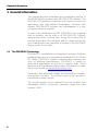
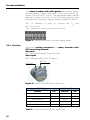
2.1 Settings Inside the Encoder
The encoder node address and bus termination must be configured during commissioning of the device. This is done by removing the back cover, i.e. unscrewing the three screws on the rear
of the encoder.
2.1.1 Node address
The node address of the encoder can be set via two decimal rotary switches located inside the back cover. The weighting (x10 and
x1) is specified beside the switches. The permissible address
range is between 0 and 99, but the lowest addresses 0 to 2 are
usually used by the master, and should not be used by the encoder. Each address used in a PROFIBUS network must be
unique and may not be used by other devices.
The device address is only read and adopted when the encoder power supply is switched on. A restart of the encoder
is therefore required in order to adopt changes made to the
address settings.
Bus termination
on/off
Node address
switches
Figure 1 View of PROFIBUS encoder PCB and
cable glands
8
Encoder Installation
2.1.2 Bus termination
In a PROFIBUS network, all devices are connected with each
other in a bus structure. Up to 32 devices (masters and/or slaves)
can be connected per segment. If more devices are needed, repeaters must be used to amplify the signals between segments.
An active termination must be added to the beginning and end of
each bus segment in order to ensure error-free operation. In rotary encoders such terminators are integrated on the PCB, and can
be activated via dip switches as shown in Figure 1. If the power
supply to the device is interrupted, the A and B lines are internally terminated by a 220 Ω resistor.
If an encoder with M12 flange sockets is used, a terminating
resistor plug is necessary for termination. This plug is attached
similar to an M12 connector. Male as well as female contacts
can be used to terminate the two ends of the bus.
2.2 Connecting the Encoder
The unit may only be installed by an authorized electrician.
National and international regulations regarding the installation
of electrical facilities must be followed.
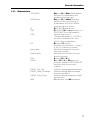
2.2.1 Power supply
Necessary mating connector for rotary encoders with M12
connecting element:
Power supply:
M12 connector, 4-pin, A-coded
Power supply
Power supply for M12 version
Function
DC: 9 V to 36 V
Figure 2 Position of the
M12 power supply connector
PIN
1
Not connected
2
0V
3
Not connected
4
Table 1 Pin layout of the
M12 power supply connector
9
Encoder Installation
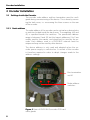
The rotary encoders with cable glands must always have a
shielded power supply cable with a line cross-section between 0.34 mm2 and 1.5 mm2. The permissible cable outside
diameter is 8 mm to 10 mm. On the PCB there are two screw
terminals with the power supply terminals marked (+) and (–).
The (+) terminal is used to connect the
(DC: 9 V to 36 V).
The (–) terminal is used to connect the 0 V line.
line
UP
Figure 3 Terminal connection of power supply cables
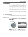
2.2.2 Bus lines
Necessary mating connectors for rotary encoders with
M12 connecting element:
Bus input:
M12 connector (female), 5-pin, B-coded
Bus output:
M12 coupling (male), 5-pin, B-coded
BUS in
BUS out
Figure 4 Position of the M12 bus connectors
BUS in lines
BUS out lines
Function
PIN
Function
PIN
Not connected
1
VP
1
2
A
2
A
Not connected
3
DGND
3
B
4
B
4
Shield
5
Shield
5
Table 2 Pin layout of the M12 BUS in/out lines
10
Encoder Installation
The rotary encoders with cable glands must have twisted
pair shielded cables in accordance with EN 50170 and
PROFIBUS guidelines. The guidelines recommend a line
cross-section greater than 0.34 mm2. The permissible cable
outside diameter is 6 mm to 8 mm. On the PCB there are
four screw terminals with the bus line terminals marked (A)
and (B).
The (A) terminal is used to connect the A line (green).
The (B) terminal is used to connect the B line (red).
Figure 5 Terminal connection of bus line cables
Note:
Since the two A terminals are internally connected to
each other (as are the two B terminals), it does not matter to which A or B terminal the bus lines are connected.
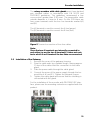
2.3 Installation of the Gateway
1. Remove the cover of the gateway housing.
2. Strip the cable ends by a suitable length, leaving approx.
15 mm of the cable shield for connection to the cable
gland.
3. Slide the power cable through the cable gland.
4. Connect the wires of the power supply through the terminal block +E and 0 V. Tighten the terminal screws.
5. Tighten the cable gland and ensure that the shielding is
connected with the gland.
For the installation of the encoder with PROFIBUS-DP interface, please see the mounting instructions supplied with the
product.
11
Encoder Installation
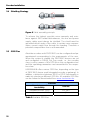
2.4 Shielding Strategy
Figure 6 Cable assembly principle
To achieve the highest possible noise immunity and resistance against EMI related disturbances, the bus and power
supply cables must always be shielded. The shield must be
grounded at both ends of the cable. In certain cases compensation current might flow through the braiding. Therefore a
potential compensation line is recommended.
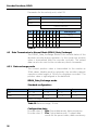
2.5 GSD Files
Absolute encoders with PROFIBUS can be configured and parameterized corresponding to the requirements of the user.
When the system is started, the PROFIBUS devices are set
and configured in DDLM_Set_Prm mode, i.e. the encoder
class is set by means of the GSD file in the configuration tool
and the operating parameters are transmitted to the respective slave.
HEIDENHAIN offers various GSD files, depending on the type
of PROFIBUS device used (integrated encoder or gateway). In
addition, a distinction between DPV0 or DPV2 functionality is
made by selecting a different GSD file. All available GSD files
can be ordered or downloaded from www.heidenhain.de.
GSD files
Encoder type and
functionality
GSD file
Integrated encoder, DPV0
enc_a401
Integrated encoder, DPV2
enc_0aaa
Table 3 Available GSD files
12
Encoder Installation
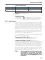
During configuration of the encoders, the various encoder
classes can be selected as described in the following chapters. The selectable parameters and functionality of the device depend on the selected encoder class. This data, saved
in the PROFIBUS master, is transferred to the encoder once
the system is powered on.
After the configuration and parameter data have been received the encoder enters normal operation with cyclic data
transfer, i.e. “DDLM_Data_Exchange mode”.
Installation of the GSD files:
1.
On the data carrier, select the GSD file of the respective
device and copy the *.gsd file into the appropriate directory of the PROFIBUS configuration tool.
2.
On the data carrier, select the bitmap file of the respective device and copy the *.bmp file into the appropriate
directory of the PROFIBUS configuration tool.
3. Update the GSD files (SCAN).
13
Encoder Installation
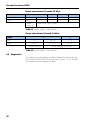
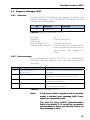
2.6 LED Display
Two LEDs on the rear of the encoder indicate the encoder
status. The module LED indicates the status of the module itself. The bus LED indicates the status of the bus. The table
below defines the diagnostic messages using the red (BUS)
and red/green (MODULE) LEDs. The function of the LED display is the same in DPV0 and DPV2 modes.
Bus
Module
Meaning
Dark
Dark
No power
Red
Green
No connection to another device
Criterion: no data exchange
Red
2)
Red
2)
Blinking
red
1)
Green
No connection to another device
No connection between EnDat
base encoder and PROFIBUS
PCB
Parameterization or configuration fault
Dark
Red
System failure
Dark
Green
Data exchange
Slave and operation OK
Cause
– Bus not connected
– Master not available / switched
off
– No connection to EnDat encoder at power up
– The received configuration differs from the supported configuration
– Parameter error in the parameterization
– Diagnosis available, slave in
data exchange mode
– Position error
Table 4 LED display
1) The blinking frequency is 0.5 Hz. The minimum indication
time is 3 s.
2) There is a position error when an alarm occurs in the encoder or if the EnDat base encoder is disconnected from the
PROFIBUS interface PCB.
14
Profile Overview
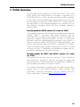
3 Profile Overview
The encoder device profiles for PROFIBUS-DPV0, DPV1 and
DPV2 define the functionality of encoders connected to a
PROFIBUS-DP bus. There are two encoder profiles available
(3.062 and 3.162) for defining the functionality of the encoder
for the different versions of PROFIBUS DP. Please refer to
the illustration on the following page for an overview of the
two different encoder profiles and the standards related to
these profiles.
Encoder profile for DPV0, version 1.1, order no. 3.062.
The operating functions of this profile are divided into two device
classes. Class 1 encoders offer basic functions that all
PROFIBUS-DP encoders must support. A class 1 encoder can
optionally support selected functions of class 2, but these
functions must be implemented according to the profile. In
order to support earlier PROFIBUS-DP implementations, the
size of the protocol data units (PDU) is limited to 16 bytes.
Class 2 encoders must support all functions of class 1 as well
as those of class 2. Parameters and diagnostic ranges are reserved for manufacturer-specific functions.
Encoder profile for DPV1 and DPV2, version 3.1, order
no. 3.162.
This profile also has two classes of devices: Class 3 with the
basic functions, and class 4 with the full range of scaling and
preset functions. Optional functions are defined in addition to
the mandatory functions of classes 3 and 4.
For further information regarding the encoder functionality,
please refer to the device profiles. These profiles and
PROFIBUS technical information can be ordered from the
PNO in Karlsruhe, Germany (www.PROFIBUS.com).
15
Profile Overview
PROFIBUS DP-V2
IEC 61158
PROFIdrive
PNO No. 3.172
I&M Functions
PNO No. 3.502
Encoder Profile
Class 3 and 4
PNO No. 3.162
PROFIBUS-DP
EN50170 Vol 2
Encoder Profile
Class 1 and 2
PNO No. 3.062
Figure 7 Overview of encoder profiles and related PROFIBUS
documents
A GSD file is used to choose between the different profile
versions. The user can select the version that fits his hardware and software. The GSD file can be downloaded from
www.heidenhain.de.
3.1 DPV0 Encoder Classes
The encoder can be configured as a class 1 or class 2
PROFIBUS slave device. As an option, the rotational speed information of the encoder can be accessed for Class 2 encoders.
CLASS 1
In class 1 configuration only output values are
assigned. Depending on the encoder resolution,
this is one output word (16 bits) or two (32 bits).
The following functions can be performed:
• Reversal of counting direction
• Diagnostic data up to octet 16
Configuration data:
Singleturn Class 1 – 16 bits: D0hex,
1 input data word,
data consistency
Multiturn
Class 1 – 32 bits: D0hex,
2 input data words,
data consistency*)
*) The data values to be transmitted are double words. Therefore, buffer consistency is used in this case.
The buffer consistency ensures that the entire data buffer is transmitted as one unit, and cannot be interrupted by other CPU processes.
16
Profile Overview
CLASS 2
In class 2 configuration output values and input
words are assigned. Depending on the encoder
resolution, this is one output word (16 bits) or
two (32 bits).
The following functions are available in addition
to the class 1 functions:
• Scaling function
• Preset function
• Speed read-out
• Extended diagnostic data
Configuration data:
Singleturn
Class 2 – 16 bits:
F0hex
1 input data word
1 output data word for the preset value
Data consistency
Multiturn
Class 2 – 32 bits:
F0hex
2 input data words
2 output data words for the preset value
Data consistency
Position +
Class 2 – 32 + 16 bits:
velocity
F1+D0hex
3 input data words
2 output data words for the preset value
Data consistency
The selection of the class depends on the demands required
by the application, but for enabling full functionality of the encoder, choosing class 2, 32-bit speed, is recommended.
3.2 DPV2 Encoder Classes
In general the encoders with PROFIBUS-DPV2 interface are
divided into two classes. As opposed to DPV0 there is only
one configuration option, telegram 81, regardless of the class.
CLASS 3
In class 3 configuration only output position values are assigned. Further functions are not
available.
Configuration data:
Standard telegram 81
17
Profile Overview
CLASS 4
In class 4 configuration output values and input
words are assigned. Depending on the encoder
resolution, this is one output word (16 bits) or
two (32 bits).
The following functions are available in class 4
parameterization:
• Code sequence
• Scaling function
• Preset function
• Extended diagnostic data
Configuration data:
Standard telegram 81
18
Encoder Functions, DPV0
4 Encoder Functions, DPV0
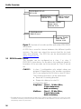
4.1 Basic Encoder Functions
The figure below gives an overview of the basic encoder
functions and how these functions are implemented within
the encoder.
Physical position
Basic function
Absolute position
Code sequence
Singleturn resolution
Number of distinguishable revolutions
Scaling function
Encoder resolution
Total measuring range
Status of the scaling function
Preset function
Preset value
Offset value
Output position value
Figure 8 Basic encoder functions
4.2 PROFIBUS Data Transmission Principle
PROFIBUS-DP devices can be configured according to the
user’s needs, and the parameters can be set to fit these requirements. In this context it is useful to know that
PROFIBUS offers three different types of data transmission.
4.2.1 Selection of the parameterization (DDLM_Set_Prm mode)
When the system is started, the PROFIBUS devices are parameterized (DDLM_Set_Prm mode), i.e. the encoder class is
set by means of the GSD file in the configuration tool (see
Chapter 3) and the operating parameters (see Chapter 4) are
transferred to the respective slave.
19
Encoder Functions, DPV0
4.2.2 Normal mode (DDLM_Data-Exchange mode)
In the normal mode (DDLM_Data-Exchange mode), data is
exchanged between master and slaves. The preset function
can be carried out only in this operating mode. Data exchange
is described in Chapter 4.5.
4.3 Configuration, DPV0
The configuration of a DPV0 encoder is conducted by choosing the encoder class, i.e. by setting the input/output data
structure. The configuration options are 16-bit, 32-bit or 32-bit
+ 16-bit speed input data (for an explanation, see Chapter
3.1).
4.4 Parameterization, DPV0
The PROFIBUS-DPV0 encoder is parameterized by means of
the operating parameters. The values selected in the configuration tool are saved in the DP master and are transferred to
the PROFIBUS-DP slave each time the network is started.
The following table lists all available parameters:
Parameter
Data type
Parameter
octet number
Device class
Code sequence
Bit
9
1
Class 2 functions
Bit
9
2
Configuration diagnostics
Bit
9
Optional
Scaling function
Bit
9
2
Encoder resolution
32-bit unsigned
10 – 13
2
Total measuring range (steps)
32-bit unsigned
14 – 17
2
Manufacturer-specific functions
Bit
26 – 28
Optional
Speed control
2 bits
39
2 ext.
Table 5 Operating parameters in DPV0
The operating parameters described in octet 9 are defined bit
by bit as follows:
Octet
9
Bits
7–0
Data
27 – 20
Operating parameters
20
Encoder Functions, DPV0
Bit
Definition
=0
=1
0
Code sequence
Clockwise (CW)
Rising position values when
shaft rotated clockwise
(seen from flange side)
Counterclockwise (CCW)
Rising position values when
shaft rotated counterclockwise
(seen from flange side)
1
Class 2 functions
Deactivated
Activated
2
Configuration diagnostics No
Yes
3
Scaling function
Scaling activated
Scaling parameters are loaded
into octets 10 to 17
Scaling deactivated
4
Reserved
for future
applications
...
7
Table 6 Octet 9, parameter definition
4.4.1 Code sequence
The code sequence defines whether the absolute position
value should increase during clockwise or counterclockwise
rotation of the shaft encoder (seen from flange side). The
code sequence is by default set to increase the absolute position value when the shaft is turned clockwise (0).
4.4.2 Class 2 functions
This bit activates or deactivates class 2 functionality. As a default, the class 2 function bit for PROFIBUS-DP encoders is
set to inactive (0). This means that this bit must be activated
during parameterization to support the class 2 functions.
Note:
If a class 1 encoder uses some optional class 2
functions, the class 2 bit must be set.
21
Encoder Functions, DPV0
4.4.3 Configuration diagnostics
The commissioning diagnostics function makes it possible for
the encoder to perform an internal diagnostic test of the encoder components responsible for position detection during a
standstill of the encoder (i.e. light unit, photovoltaic cells etc.).
In combination with the position alarms it enables thorough
checking of whether the position values provided by the absolute encoder are correct. The commissioning diagnostics
function is started by the commissioning bit in the operating
parameters. If an error is found within the absolute encoder,
the diagnostic function indicates this with the commissioning
diagnostics alarm bit (see Chapter 4.6.2).
The commissioning diagnostics function is an option. To find
out whether the encoder supports commissioning diagnostics, the diagnostic function must read the “operating status”
and the commissioning diagnostics bit must be checked.
4.4.4 Scaling function
The scaling function uses a software program to convert the
encoder’s physical absolute position value in order to change
the resolution of the encoder.
The parameters “Measuring units per revolution” and “Total
measuring range in measuring steps” are the scaling parameters set by the parameter function in octets 10 to 17. Scaling
is active only if the control bit for the scaling function is set. If
the scaling function bit is set to 0, the scaling function is disabled.
Note:
After downloading new scaling parameters,
the Preset function must be used to set the
encoder starting point to the absolute position 0 or to any desired starting position
within the scaled operating range.
4.4.5 Measuring steps per revolution
The total measuring range is calculated by multiplying the
singleturn resolution with the number of distinguishable revolutions.
The default settings for singleturn encoders are:
Measuring steps per revolution = 819210 (213)
Total measuring range in measuring steps = 819210 (213 · 20)
The default settings for multiturn encoders are:
Measuring steps per revolution = 819210 (213)
Total measuring range in measuring steps =
33 554 43210 (213 · 212)
22
Encoder Functions, DPV0
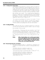
Format of the scaling parameters:
Octet:
10
11
12
13
Bits
31 – 24
23 – 16
15 – 8
7–0
Data
231 – 224
223 – 216
215 – 28
27 – 2 0
Encoder resolution
Table 7 Format of the singleturn scaling parameters
Octet:
14
15
16
17
Bits
31 – 24
23 – 16
15 – 8
7–0
Data
231 – 224
223 – 216
215 – 28
27 – 2 0
Total measuring range
Table 8 Format of the multiturn scaling parameters
The data format for both scaling parameters is 32 bits without
algebraic sign, with a value range from 20 to 232. The permissible value range is limited by the resolution of the rotary
encoder. For a 25-bit encoder with a singleturn resolution of
13 bits, the permissible value range for “Measuring steps per
revolution” is from 20 to 213 (8192), and for the “Total measuring range in measuring steps” the permissible value range
is from 20 to 225 (33 554 432). The scaling parameters are securely stored in the PROFIBUS-DP master and are reloaded
into the encoder upon each power-up. Both parameters are
output data in 32-bit format.
Example of scaling and entry:
If the user wants to scale the encoder to a singleturn resolution of 4000 unique positions per revolution and the total
number of revolutions to 3200, the following configuration is
to be selected:
Encoder resolution
= 400010 steps
Total measuring range in measuring steps
= 4000 steps x 3200 revolutions
= 12 800 00010
Entry in the master configuration software:
Measuring steps per revolution = 4000
Total measuring range (steps) = 12 800 000
23
Encoder Functions, DPV0
4.4.6 Total measuring range (steps)
The total measuring range is defined by the parameter “Total
measuring range in measuring steps.” The encoder has two
different operating modes, depending on the specified measuring range. When the encoder receives a parameter message, it checks the scaling parameters for whether binary
scaling can be used. If binary scaling can be used, the encoder selects operating mode A (see following explanation). If
not, operating mode B is selected.
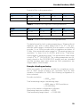
A. Cyclic operation (binary scaling)
Measuring mode A is selected if the encoder operates with
2x revolutions (number of revolutions equals 2, 4, 8, 16, 32,
64, 128, 256, 512, 1024, 2048 or 4096).
If the desired measuring range is equal to the specified singleturn resolution ≤ 2x (with x ≤ 12), the rotary encoder operates in endless cyclic operation (from 0 to max. position value, from 0 to max. position value, etc.). If rotation of the axis
to be measured causes the position value of the encoder to
exceed the maximum value (total measuring range), the encoder indicates 0 as the position value again.
Example of cyclic scaling:
Measuring steps per revolution
Total measuring range
Figure 9 Cyclic scaling
24
=
=
1000
32 000 (25 = number
of revolutions: 32)
Encoder Functions, DPV0
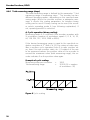
B. Acyclic operation
If the measuring range is used to limit the value range of the
encoder to a value other than the specified singleturn resolution * 2x, the output position value is limited within the operating range. If rotation of the encoder shaft causes the position value to exceed the maximum value or fall below 0, the
encoder indicates the value of the measuring range. See figure below.
Example of acyclic scaling:
Measuring steps per revolution = 100
Total measuring range
= 5000 (number
of revolutions: 50)
Figure 10 Acyclic scaling
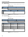
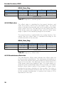
4.4.7 Velocity function
The velocity data can be accessed if class 2 32-bit + velocity
configuration is used. In this case the input data consists of
32-bit position data plus 16-bit signed velocity data. The velocity value is negative in counterclockwise direction if the code
sequence is set to clockwise. If the measured velocity is
greater than the value that can be preset for the selected
velocity unit, the value is set to 0x7FFF (32768) or 0x8000
(–32768) depending on the direction of shaft rotation.
Note:
If one of the time-based velocity units is used
and scaling is set for the encoder, the velocity calculation is based on the scaled position
value. Consequently, the accuracy of the velocity value depends on the scaling set for
the encoder.
25
Encoder Functions, DPV0
Parameter for the velocity unit, octet 39.
Octet:
39
Bits
7–0
Data
27 – 2 0
Velocity function
Bit
7
6
5
4
0
0
3
2
1
0
Velocity unit
Steps/s
0
1
Steps/100 ms
1
0
Steps/10 ms
1
1
Revolutions per minute
Table 9 Octet 39, velocity function
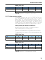
4.5 Data Transmission in Normal Mode (DDLM_Data_Exchange)
The DDLM_Data_Exchange mode is the normal status of the
absolute encoder during operation. In this mode the position
value is transmitted from the encoder cyclically. The output
data can also be sent to the encoder as preset commands.
4.5.1 Data exchange mode
The current position value is transmitted to the master as
32-bit values (double word) or optionally: the encoder supports
a position value length of 16 bits for singleturn encoders. The
position value is right-aligned in the data field.
DDLM_Data_Exchange mode
Standard configuration:
Octet:
1
2
3
4
Bits
31 – 24
23 – 16
15 – 8
7–0
Data
231 – 224
223 – 216
215 – 28
27 – 2 0
Data_Exchange – 32 bits
Table 10 Data exchange, 32 bits
Configuration data:
Encoder class 1 D116 2 input data words, data consistency
Encoder class 2 F116 2 input data words, 2 output data
words for the preset value, data consistency
26
Encoder Functions, DPV0
Optional configuration:
Octet:
1
2
Bits
15 – 8
7–0
Data
215 – 28
27 – 2 0
Data_Exchange – 16 bits
Table 11 Data exchange, 16 bits
Configuration data:
Encoder class 1 D116 1 input data word, data consistency
Encoder class 2 F016 1 input data word, 1 output data word
for the preset value, data consistency
4.5.2 Preset function
The preset function enables adapting the encoder’s position
value to a known mechanical reference point of the system.
The preset function sets the actual value of the encoder to
zero or to the selected preset value. If the Data_Exchange
function is activated the preset value is stored in non-volatile
memory in the encoder as an input value. In case of a power
interruption the preset value is reloaded at start-up. If the
scaling function is active, the preset function is applied after
the scaling function. This means that the preset value is entered in the current measuring step unit.
The most significant bit (MSB) of the preset value controls
the preset function as follows:
Standard mode: MSB = 0 (bit 31, optionally bit 15)
The encoder does not change the preset value.
Activated mode: MSB = 1 (bit 31, optionally bit 15)
For MSB = 1 the encoder accepts the transmitted value (bits
0 to 30) as preset value in binary code. The encoder reads the
current position value and calculates an offset value on the
basis of the preset value. The position value is shifted by the
calculated offset value. If the output position value equals the
preset value, the preset mode is terminated and the MSB can
be set to 0 by the master. The resulting offset value can be
read by means of the diagnostic function.
Note:
The preset function should be used only during standstill of the encoder. The encoder
type limits the number of possible preset
cycles; please consult HEIDENHAIN for more
information.
27
Encoder Functions, DPV0
Preset value format (2 words, 32 bits):
Octet:
1
2
3
4
Bits
31
Data
0/1
30 –- 24
23 – 16
15 – 8
7–0
230 – 224
223 – 216
215 – 28
27 – 2 0
Preset
control bit
Preset value, up to 31 bits
Table 12 Preset value, 32-bit format
Preset value format (1 word, 16 bits):
Octet:
1
2
Bits
15
14 – 8
7–0
Data
0/1
214 – 28
27 – 2 0
Preset control bit
Preset value, up to 15 bits
Table 13 Preset value, 16-bit format
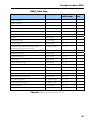
4.6 Diagnostics
The diagnostic information contains diagnostic data that is defined in the PROFIBUS-DP specification (octet 1 to 6), as well
as encoder-specific diagnostic data:
28
Encoder Functions, DPV0
DDLM_Slave_Diag
Diagnostic function
Data type
Diagnostic
octet number
Device
class
Station status 1
Bit
1
1
Station status 2
Bit
2
1
Station status 3
Bit
3
1
Diagnostic master address
Bit
4
1
PNO identification number
Bit
5–6
1
Extended diagnostic header
Octet string
7
1
Alarms
Octet string
8
1
Operating status
Octet string
9
1
Encoder type
Octet string
10
1
Singleturn resolution (rotary encoder)
Measuring step (linear encoder)
32 without sign
11 – 14
1
Number of distinguishable revolutions
16 without sign
15, 16
1
Additional alarms
Octet string
17
2
Supported alarms
Octet string
18, 19
2
Warnings
Octet string
20, 21
2
Supported warnings
Octet string
22, 23
2
Profile version
Octet string
24, 25
2
Software version
Octet string
26, 27
2
Operating time
32 without sign
28 – 31
2
Offset value
32 with sign
32 – 35
2
Manufacturer offset value
32 with sign
36 – 39
2
Encoder resolution
32 without sign
40 – 43
2
Total measuring range
32 without sign
44 – 47
2
Serial number
ASCII string
48 – 57
2
58 – 61
2
Reserved for future definitions
Table 14 Diagnostic information, DPV0
29
Encoder Functions, DPV0
Note:
The length of the diagnostic information of
class 1 is limited to 16 bytes. This is compatible with former DP versions. For PROFIBUS-DP
class 2 encoders the length of the encoderspecific diagnostic data including the extended
diagnostic header is 57 bytes.
The DDLM_Slave_Diag memory range up to octet 99 is reserved for future diagnostic data of class 2.
4.6.1 Diagnostic header
The header byte specifies the length of the encoder diagnostics including the header byte. The format of the transmission
length is hexadecimal. For PROFIBUS-DP class 1 encoders
the length of the encoder-specific diagnostic data is 10 bytes
(0Ahex).
DDLM_Slave_Diag
Octet
7
Bits
7
6
5–0
Data
0
0
xxh
Set to 00
Length including header
Extended diagnostics
Table 15 Diagnostic header
4.6.2 Alarms
An alarm is triggered if a malfunction in the encoder can lead
to incorrect position values. Octet 8 in the diagnostic function
(DDLM_Slave_Diag) indicates the status of the alarms. Additional alarms for device class 2 are added to diagnostic octet 17.
If an alarm is triggered, the Ext_Diag bit and the Stat_Diag bit
in the diagnostic function are set to high until the alarm is reset and the encoder can provide correct position values.
Alarms can be reset (deleted) when all encoder parameters
are within the specified value ranges and the position value is
correct.
Note:
30
Not every encoder supports every alarm. For
class 2 encoders the “Supported alarms” diagnostic information (see chapter 4.6.8) enables
you to find out which specific alarm bits are
supported.
Encoder Functions, DPV0
DDLM_Slave_Diag
Octet
8
Bits
7–0
Alarms
Bit
Definition
=0
=1
0
Position error
No
Yes
1
Voltage supply error
No
Yes
2
Current is too high
No
Yes
3
Configuration diagnostics
OK
Errors
4
Memory error
No
Yes
5
Currently
not
assigned
6
7
Table 16 Alarms
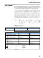
4.6.3 Operating status
Octet 9 in the diagnostic function provides information about
encoder-specific parameters. A class 2 encoder sets the functionality bit for class 2 commands to show the DP master that
all commands of class 2 are supported. The DP master must
activate the functionality bit of class 2 in the parameter message (DDLM_Set-Prm) to enable the use of class 2 functions.
The status bit of the scaling function is set when the scaling
function is activated and the resolution of the encoder is calculated using the scaling parameters.
DDLM_Slave_Diag
Octet
Bits
9
7–0
Operating status
31
Encoder Functions, DPV0
Bit
Definition
=0
=1
0
Code sequence
Increasing position values
for clockwise revolutions
(seen from the flange)
Increasing position values
for counterclockwise revolutions (seen from the flange)
1
Class 2 functions
No, not supported
Yes
2
Configuration diagnostics
No, not supported
Yes
3
Scaling function status
Scaling disabled
Scaling enabled
4
Currently
not
assigned
5
6
7
Table 17 Operating status
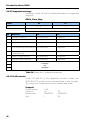
4.6.4 Encoder type
The type of encoder can be read in octet 10 of the diagnostic
function. The type of encoder is defined in hexadecimal coding in the range from 0 to FF.
DDLM_Slave_Diag
Octet
10
Bits
0 - FF
Encoder type
Code
Definition
00
Absolute singleturn encoder
01
Absolute multiturn encoder
02
Absolute singleturn encoder with electronic revolution counter
03
Incremental rotary encoder
04
Incremental rotary encoder with battery buffer
05
Incremental linear encoder
06
Incremental linear encoder with battery buffer
07
Absolute linear encoder
08
Absolute linear encoder with periodic coding
09
•
•
•
Currently
not
assigned
FF
Table 18 Diagnostics, encoder type
32
Encoder Functions, DPV0
4.6.5 Singleturn resolution or measuring step
The meaning of the singleturn resolution in the diagnostic
function differs depending on the type of encoder.
For rotary or angle encoders, the diagnostic octets 11 to 14 indicate the physical resolution as the number of measuring
steps per revolution that is transmitted for the absolute singleturn position value. The maximum singleturn resolution is 232.
For linear encoders the measuring steps are shown in respect
to the resolution of the encoder, i.e. each increment of the
measuring step equals the actual resolution of the linear encoder in use. Typical values for linear resolution are 1 μm to
40 μm.
DDLM_Slave_Diag
Octet
11
12
13
14
Bits
31 – 24
23 – 16
15 – 8
7–0
Data
231 – 224
223 – 216
215 – 28
27 – 2 0
Singleturn resolution
Table 19 Diagnostics, singleturn resolution
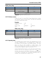
4.6.6 Number of distinguishable revolutions
The number of distinguishable revolutions the encoder can
transmit is defined by octets 15 and 16 of the diagnostic function. In accordance with the formula below, the measuring
range for a multiturn encoder results from the number of distinguishable revolutions multiplied by the singleturn resolution. The maximum number of distinguishable revolutions is
65 536 (16 bits).
Measuring range = number of distinguishable revolutions x
singleturn resolution
DDLM_Slave_Diag
Octet
Bits
15
16
15 – 8
7–0
Number of distinguishable revolutions
Table 20 Diagnostics, number of distinguishable revolutions
33
Encoder Functions, DPV0
4.6.7 Additional alarms
Diagnostic octet 17 indicates additional alarms for device
class 2.
DDLM_Slave_Diag
Octet
17
Bits
7–0
Additional alarms
Bit
Definition
=0
=1
0
Currently
not
assigned
•
7
Table 21 Diagnostics, additional alarms
4.6.8 Supported alarms
Diagnostic octets 18 and 19 contain information on the supported alarms.
DDLM_Slave_Diag
Octet
Bits
18
19
15 – 8
7–0
Supported alarms
Bit
Definition
=0
=1
0
Position error
Not supported
Supported
1
Voltage supply error
Not supported
Supported
2
Current is too high
Not supported
Supported
3
Configuration diagnostics
Not supported
Supported
4
Memory error
Not supported
Supported
5
•
15
Currently
not
assigned
Table 22 Diagnostics, supported alarms
34
Encoder Functions, DPV0
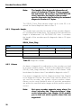
4.6.9 Warnings
Warnings indicate that tolerances for certain internal parameters of the encoders have been exceeded. Contrary to alarms,
no faulty position values are expected in case of warnings.
Octets 20 and 21 of the diagnostic function indicate the status of the warnings. If a warning is set, the Ext_Diag bit in the
diagnostic function is set to logical 1 until the warning is reset. All warnings are deleted as soon as the diagnostic message of the encoder has been read. However, if the tolerances are still exceeded, the warning is activated again. The
warning “Maximum operating time exceeded” (bit 4) is not
activated again until the next time the system is switched on.
Note:
Not every encoder supports every warning.
Please refer to the diagnostic information under “Supported Warnings” (see chapter 4.6.10)
for information on the support of specific
warnings.
DDLM_Slave_Diag
Octet
20
Bits
21
15 – 8
7–0
Warnings
Bit
Definition
=0
=1
0
Frequency exceeded
No
Yes
1
Temperature exceeded
No
Yes
2
Light control reserve
Not reached
Reached
3
CPU monitoring status
OK
Reset
4
Maximum operating time
exceeded
No
Yes
5
Battery charge
OK
Too low
6
Reference point
Reached
Not reached
7
•
15
Currently
not
assigned
Table 23 Diagnostics, warnings
35
Encoder Functions, DPV0
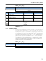
4.6.10 Supported warnings
Diagnostic octets 22 and 23 contain information on supported
warnings.
DDLM_Slave_Diag
Octet
Bits
22
23
15 – 8
7–0
Supported warnings
Bit
Definition
=0
=1
0
Frequency warning
Not supported
Supported
1
Temperature warning
Not supported
Supported
2
Light control reserve warning
Not supported
Supported
3
CPU monitoring status warning Not supported
Supported
4
Maximum operating time exceeded warning
Supported
5
Battery charge warning
Not supported
Supported
6
Reference point warning
Not supported
Supported
Not supported
7
Currently
not
assigned
•
15
Table 24 Diagnostics, supported warnings
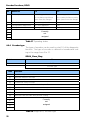
4.6.11 Profile version
Octets 24 and 25 of the diagnostic function contain the
PROFIBUS-DP profile version implemented in the encoder.
The octets are combined as revision number and index.
Example:
Profile version:
Octet no.:
Binary code:
Hex:
36
1.40
24
00000001
1
25
01000000
40
Encoder Functions, DPV0
DDLM_Slave_Diag
Octet
24
25
Bits
15 – 8
7–0
Data
27 – 2 0
27 – 2 0
Revision number
Index
Profile version
Table 25 Diagnostics, profile version
4.6.12 Software version
Octets 26 and 27 of the DDLM_Slave_Diag function contain
the software version of the encoder. The octets are combined
as revision number and index.
Example:
Software version:
Octet no.:
Binary code:
Hex:
1.40
26
00000001
1
27
01000000
40
DDLM_Slave_Diag
Octet
26
27
Bits
15 – 8
7–0
Data
27 – 2 0
27 – 2 0
Revision number
Index
Software version
Table 26 Diagnostics, software version
4.6.13 Operating time
The operating time monitor stores the operating time of the
encoder in operating hours. The operating time is saved every
six minutes in the encoder’s non-volatile memory. This happens as long as the encoder is under power. The
DDLM_Slave_Diag function displays the operating time as a 32bit value without algebraic sign in increments of 0.1 h.
If the operating time function is not used, the encoder manufacturer sets it to the maximum value (FFFF FFFFhex). The
encoder manufacturer can define a maximum operating time.
If this limit is exceeded, the “Maximum operating time exceeded” bit is activated (see Chapter 4.6.9).
37
Encoder Functions, DPV0
DDLM_Slave_Diag
Octet
28
29
30
31
Bits
31 – 24
23 – 16
15 – 8
7–0
Data
231 – 224
223 – 216
215 – 28
27 – 2 0
Operating time
Table 27 Diagnostics, operating time
4.6.14 Offset value
The offset value is calculated by the preset function, and
shifts the position value by the calculated value. The offset
value is stored in the encoder and can be read from the diagnostic octets 32 to 35. The data type for the offset value is a
32-bit binary value with algebraic sign, and the offset value
range is equal to the measuring range of the encoder.
The preset function is applied after the scaling function. This
means that the offset value is indicated according to the
scaled resolution of the encoder.
DDLM_Slave_Diag
Octet
32
33
34
35
Bits
31 – 24
23 – 16
15 – 8
7–0
Data
231 – 224
223 – 216
215 – 28
27 – 2 0
Offset value
Table 28 Diagnostics, offset value
4.6.15 Manufacturer offset value
The manufacturer offset value indicates the offset value set
by the encoder manufacturer. This value gives information on
the shift of the position zero point relative to the physical zero
point of the encoder. The data type for the offset value is a
32-bit binary value with algebraic sign. The value range corresponds to the measuring range of the encoder. The manufacturer offset value is given in the number of steps corresponding to the basic resolution of the encoder. The value is
stored in write-protected memory and can only be changed
by the encoder manufacturer. In practice this value is of no
importance to the user.
38
Encoder Functions, DPV0
DDLM_Slave_Diag
Octet
36
37
38
39
Bits
31 – 24
23 – 16
15 – 8
7–0
Data
231 – 224
223 – 216
215 – 28
27 – 2 0
Manufacturer offset value
Table 29 Diagnostics, manufacturer offset value
4.6.16 Scaling parameters settings
The scaling parameters are set in the DDLM_Set_Prm function. The parameters are stored in octets 40 to 47 of the diagnostic data. The “Measuring steps per revolution” and “Total measuring range in measuring steps” parameters specify
the desired resolution of the encoder. The status bit of the
scaling function in the operating status (octet 9 of the diagnostic data) indicates whether the scaling function is active.
Values preset by the encoder manufacturer:
Measuring steps per revolution = singleturn resolution
Total measuring range in measuring steps =
singleturn resolution x number of distinguishable revolutions
The data type for both values is 32 bits without algebraic sign.
DDLM_Slave_Diag
Octet
40
41
42
43
Bits
31 – 24
23 – 16
15 – 8
7–0
Data
231 – 224
223 – 216
215 – 28
27 – 2 0
Encoder resolution
DDLM_Slave_Diag
Octet
Bits
Data
44
45
46
31 – 24
23 – 16
15 – 8
231
–
224
223
–
216
215
–
47
28
7–0
27 – 2 0
Total measuring range
Table 30 Diagnostics, scaling parameter settings
39
Encoder Functions, DPV0
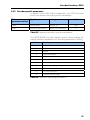
4.6.17 Encoder serial number
Octets 48 to 57 of the diagnostic function provide the serial
number of the encoder as an ASCII string of 10 characters.
DDLM_Slave_Diag
Octet
48 – 57
Bits
79 – 0
Data
ASCII
Serial number
Example of a serial number:
Octet
48
49
50
51
52
53
54
55
56
57
ASCII string
30
30
30
35
39
46
38
44
45
35
Serial (hex.)
0
0
0
5
9
F
8
D
E
5
Serial (dec.)
9434 2629
Table 31 Diagnostics, encoder serial number
40
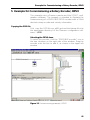
Example for Commissioning a Rotary Encoder, DPV0
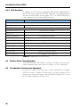
5 Example for Commissioning a Rotary Encoder, DPV0
This example uses a Siemens master and the SCOUT configuration software. The example is intended to illustrate the
commissioning of a PROFUBUS-DPV0 encoder with a 25-bit
absolute rotary encoder and velocity information.
Copying the GSD file
First, copy the GSD file enc_a401.gsd and the bitmap file into
the appropriate directory for the Siemens configuration software: ...\GSD.
Selecting the DPV0 slave
To select the encoder: click the “PROFIBUS encoder” icon in
the tree structure on the right side of the window. Drag the
encoder onto the bus to add it, as shown in the upper left
window.
Figure 11 Commissioning example, DPV0
41
Example for Commissioning a Rotary Encoder, DPV0
A PROFIBUS address must be assigned when dropping the
encoder onto the bus. Naturally this address must be the
same as that assigned using the hardware address switches
on the encoder PCB (see chapter 2.1.1).
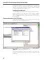
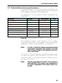
Configuring the DPV0 slave
To configure the encoder for 25-bit position value plus velocity data, choose the “Encoder Class 2 32-Bit velocity” configuration option in the map structure. Insert the chosen configuration by dragging it to the configuration area in the lower left
of the window.
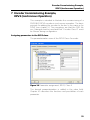
Assigning parameters to the DPV0 slave
Open the parameterization view by double-clicking the configuration row in the configuration view.
Figure 12 Parameter assignment, DPV0
The desired parameter values are added in the value field.
Chapter 4.4 describes the functions and possibilities of each
parameter.
42
Example for Commissioning a Rotary Encoder, DPV0
After the parameters have been added, the encoder will enter
data exchange mode and is thereby commissioned for the
bus.
Note:
Please refer to the respective manufacturer’s
information on the configuration of other
PROFIBUS-DP master interface modules.
43
Encoder Functions, DPV2
6 Encoder Functions, DPV2
The DPV2 GSD file can be used to configure the PROFIBUS
DP encoder to include DPV2 functionality. DPV2 functionality
includes isochronous operation, acyclic data exchange and
slave-to-slave communication. A DPV2 encoder can only be
configured to use standard telegram 81 for I/O data, meaning
4-byte output and 12-byte input. Standard telegram 81 is defined in the PROFIdrive profile and is adapted to the DPV2
PROFIBUS profile for encoders (3.162).
Standard telegram 81:
PZD number
(process data
exchange)
Setpoint
1
2
STW2
G1_STW1
Output data from master
PZD number
1
2
3
4
Actual value
ZSW2
G1_ZSW1
G1_XIST1
G1_XIST2
Input data to master
Table 32 Standard telegram 81
The mapped signals are described in the following table:
Signal
Control
word 2
Status
word 2
Sensor 1
control
word
Sensor 1
status word
Sensor 1
Actual position value 1
Sensor 1
Actual position value 2
Abbrevia- Length
tion
16 or 32
bits
Input data / Output data
STW2
16
ZSW2
16
G1_STW1
16
Output, control word from
master
Output, status word from
master
Input, control word from
encoder
G1_ZSW1
16
G1_XIST1
32
G1_XIST2
32
Table 33 Telegram 81, signals
44
Input, status word from
encoder
Input, left-justified absolute
position value from encoder
Input, right-justified
absolute position value from
encoder
Encoder Functions, DPV2
Control word 2 (bits 12 to 15) is referred to as the master’s
sign of life, and status word 2 (bits 12 to 15) as the slave’s
sign of life. These signals are essential for controlling the
clock synchronization. The G1_XIST1 and G1_XIST2 signals
consist of the absolute position values in binary format. By
default, G1_XIST1 is left-aligned and G1_XIST2 is rightaligned; in case of differing formats the shift factor is in parameter P979 (see chapter 6.2.1). Both G1_XIST1 and
G1_XIST2 are affected by changes in the parameterization,
and in case of encoder error the error message is displayed in
G1_XIST2.
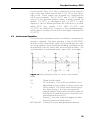
6.1 Isochronous Operation
The isochronous operation mode is used when real-time positioning is required. The basic principle is that all PROFIBUS
devices on the network are clock-synchronized with the master using a global control broadcast enabling simultaneous data acquisition from all slaves with microsecond accuracy. The
synchronization is monitored using “sign of life” messages.
Figure 13 Basic principle of the DP cycle in isochronous
mode
GC
TDP
Global control signal
DP cycle time, 1 ms to 32 ms (default: 2 ms),
depending on the number of slaves on the bus
At the start of TI all slaves must read the posiTI
tion data. During TI all slaves must put the
sampled data in the respective buffer ready for
the Master to read (this process must be completed before the next GC).
During T0 the slave reads the diagnostic data
TT0
from the master and executes it.
MSG,Res/GC Channel for acyclic data (parameter channel)
45
Encoder Functions, DPV2
6.2 Exchange of Acyclic Data
The exchange of acyclic data is conducted in the parameter
channel. The exchange of acyclic data enables parameterization during runtime. The exchange of acyclic data is conducted parallel to the cyclic data communication but with a
lower priority. The parameters accessible in the acyclic data
channel are divided into different categories.
6.2.1 PROFIdrive parameters
The encoder profile for DPV2 has adopted certain standard
PROFIdrive parameters. The HEIDENHAIN encoder supports
the following parameters:
PNU
(parameter number)
Significance
Data type
918
Node address
Unsigned16
922
Telegram selection
Unsigned16
925
Number of master sign-of-life failures that can be tolerated
R/W
R
R
R/W
964
Device identification
Array [n] Unsigned16
R
965
PROFIdrive profile number
Octet string 2
R
971
Transfer to non-volatile memory
Unsigned16
W
979
Sensor format
Array [n] Unsigned32
R
Table 34 Supported PROFIdrive parameters
46
Encoder Functions, DPV2
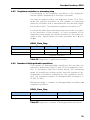
6.2.2 Encoder-specific parameters
In addition to the PROFIdrive parameters, the DPV2 encoder
profile also defines encoder-specific parameters.
PNU
(parameter number)
Significance
Data type
65000
Preset value
Integer 32
65001
Operating parameters
Array [n] Unsigned32
R/W
R/W
R
Table 35 Supported encoder-specific parameters
The HEIDENHAIN encoder supports preset values and the following subindex parameters of operating parameters (65001).
Subindex
Meaning
0
Header
1
Operating status
2
Alarms
3
Supported alarms
4
Warnings
5
Supported warnings
6
Encoder profile version
7
Not supported (operating time)
8
Offset value
9
Encoder resolution
10
Total measuring range
Table 36 Supported operating parameters
47
Encoder Functions, DPV2
6.2.3 I&M functions
In addition to PROFIdrive parameter 964 (device identification),
the encoder also supports the I&M functions. The I&M functions
can be accessed with record index 255. The HEIDENHAIN encoder supports the following I&M functions:
Contents
Coding
Header
Manufacturer-specific
Security code for write-access to parameters
I&M block
MANUFACTURER_ID
Manufacturer_Id (284)
Encoder part number
ORDER_ID
SERIAL_NUMBER
Encoder serial number
HARDWARE_REVISION
0x0000 (not used)
SOFTWARE_REVISION
Software revision including software version status, e.g. “V1.3.0”
REVISION_COUNTER
0x0000 (not used)
PROFILE_ID
“3D00“ (encoder profile DPV2)
PROFILE_SPECIFIC_TYPE
IM_VERSION
IM_SUPPORTED
See table in encoder profile
Version of the I&M profile
= 0 (obligatory I&M support)
Table 37 Supported I&M functions
6.3 Slave-to-Slave Communication
The HEIDENHAIN PROFIBUS encoder supports the slave-toslave communication principle as a slave, i.e. as “publisher.”
6.4 Configuration (Isochronous Operation)
A class 3 or class 4 encoder type can be selected to configure
a DV2 encoder. Chapter 3.2 describes the functionality of the
various encoder class types, but standard telegram 81 is used
for I/O data regardless of the class.
48
Encoder Functions, DPV2
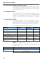
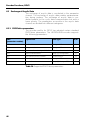
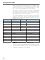
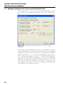
6.5 Parameterization (Isochronous Parameters)
The parameterization of the DPV2 encoder functionality is divided into two steps. The parameterization data is transferred
to the encoder in Structure_ Prm_Data blocks.
The parameters for the general encoder functionality are
listed below.
Parameter
Data type
Octet number
Class
Code sequence
Bit
4 bit 0
4
Class 4 enable
Bit
4 bit 1
4
G1_XIST1 preset control
Bit
4 bit 2
4
Scaling function control
Bit
4 bit 3
4
Ext_Diag enable
Bit
4 bit 4
4
Measuring steps per revolution
Unsigned32
5–8
4
Total measuring range
Unsigned32
9 – 12
4
Maximum tolerated failures of
MasterLifeSign
Unsigned8
13
4
Table 38 Encoder parameters, DPV2
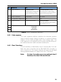
The parameter functions, code sequence, class 4 enable,
scaling and scaling control are analogous to the corresponding
parameters in DPV0. For an explanation, see chapter 4.4.
Note:
In order to meet the timing requirement during
isochronous operation, the encoder only tolerates binary scaling for the singleturn and multiturn resolutions.
The G1_XIST1 control bit determines whether the preset value
can affect the position value presented in G1_XIST1. If the
control bit is set to 1, the preset value will not affect the position value in G1_XIST1.
Note:
This bit only affects G1_XIST1. If the preset is
set it will affect the position value presented in
G1_XIST2, regardless of the status of this control bit.
49
Encoder Functions, DPV2
If the Ext_Diag enable control bit is set to 0 (default value),
only the first six bytes of the diagnostics message are transmitted. If the bit is set to 1, the complete diagnosis is available, i.e. the channel-related diagnosis is transmitted.
The MasterLifeSign byte is used for enabling programming of
the number of allowed failures of the master sign of life.
When the number is reached, an error message (0x0F02) is
sent as diagnosis in the G1_XIST2 signal.
The following parameters must be considered when parameterizing the isochronous mode. The time-based parameters
are globally set by the master application, and can’t be set individually for each slave.
Parameter
Data type
Value
Comments
Structure_Length
Unsigned8
0x1C (decimal 28)
Structure_Type
Unsigned8
0x04
IsoM parameters
Slot no.
Unsigned8
0x00
Communication with entire
device
Reserved
Unsigned8
0x00
Version
Unsigned8
0x01
TBASE_DP
Unsigned32
375/750/1500/… Set by master
TDP
Unsigned16
Set by master
First revision
TMAPC
Unsigned8
Set by master
TBASE_IO
Unsigned32
Set by master
TI
Unsigned16
Set by master
TO
Unsigned16
Set by master
TDX
Unsigned32
Set by master
TPLL_W
Unsigned16
Set by master
TPLL_D
Unsigned16
Set by master
Table 39 Parameters of the isochronous mode
The various time-based parameters are defined in the PROFIdrive V3.1 profile (chapter 6.2.1). For general explanations and
comments, see chapter 6.1 of this manual.
50
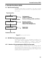
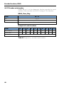
Encoder Functions, DPV2
6.6 Diagnostic Messages, DPV2
6.6.1 Overview
Encoder profile 3.162 defines the support for alarms and
warning messages. The HEIDENHAIN PROFIBUS encoder
supports the following alarm:
Bit
0
Definition
Error type
Position error
22
Table 40 Diagnostic messages, DPV2
Error type:
Definition:
GSD inputs:
Channel_Diag (22) =
Channel_Diag_Help (22) =
22
Position value error
“Position value error”
“The encoder has an internal error
and is not able to provide an accurate position value; change encoder”
6.6.2 Error messages
Error messages are sent in G1_XIST2. The HEIDENHAIN
PROFIBUS encoder supports error messages according to
the profile.
Error
Meaning
Description
0x0001
Sensor group error
(position error)
The encoder is not able to provide a correct position value.
0x0F01
The command is not supported
In G1_STW1 the master application sent a command that is not supported by the encoder.
0x0F02
Master’s sign of life fault
The number of permissible failures of the master’s
life sign was exceeded.
0x0F04
Synchronization fault
The number of permissible failures for the bus
cycle signal was exceeded.
Table 41 Error messages, DPV2
Note:
If the preset value is negative and an absolute
preset is entered, error message 0xF01 (command not supported) is set.
The limit for error 0x0F04 (Synchronization
fault) is by default 5, i.e. up to five consecutive
synchronization faults are allowed before an
error message is sent.
51
Encoder Functions, DPV2
6.6.3 Isochronous synchronization principle
The chart below describes the synchronization principle of the
encoder when adapting to a synchronized DP cycle, IRT mode
operation.
1. Start-up
Standard PROFIBUS commissioning, i.e.
– Installation
– Power-up
– Configuration (DPV2 GSD file mandatory)
– Parameterization
2. Synchronization
The encoder is synchronized with the DP cycle according to
the parameterization selected.
3. Master Life Sign
After synchronization the encoder expects to read the Master
Life Sign (MLS). The MLS is generated by the master and
presented in STW2 (control word 2, bits 12 to 15). The MLS is
counted during each DP cycle: 1 to 15 cyclically (0 is not a valid value).
4. Slave Life Sign
After the encoder is synchronized with the MLS, it acknowledges this by generating the Slave Life Sign (SLS). The SLS is
presented in ZSW2 (status word 2, bits 12 to 15). In accordance with the MLS, it must be counted from 1 to 15 cyclically
(0 is not a valid value), although it is not mandatory that MLS
and SLS be identical in each DP cycle.
5. Operating mode
After detection of the correct SLS by the master, any current
error codes must be acknowledged. This is done by the master clearing bit 15 in the sensor control word (G1_STW). The
encoder acknowledges this by resetting the sensor error code
bit (15) in the sensor status word (G1_ZSW), and also clears
the error message presented in G1_XIST2. If this is done successfully, the encoder is in operating mode and fully synchronized with the DP cycle.
52
Encoder Commissioning Example,
DPV2 (Isochronous Operation)
7 Encoder Commissioning Example,
DPV2 (Isochronous Operation)
This example is intended to illustrate the commissioning of a
PROFIBUS-DPV2 encoder in isochronous operation. The basic
principle for adding the encoder to the bus is the same as for
DPV0 (see chapter 5). The exceptions are that the GSD file
enc_0aaa.gsd must be used and that “Encoder Class 4” must
be chosen during configuration.
Assigning parameters to the DPV2 slave
The parameterization view of the DPV2 Class 4 encoder.
Figure 14 Parameter assignment, DPV2, Class 4
The desired parameterization is added in the value field.
Chapter 6.5 describes the functions and possibilities of each
parameter.
53
Encoder Commissioning Example,
DPV2 (Isochronous Operation)
7.1 Parameter Settings for the Isochronous Mode: DPV2 Slave
The parameters for the isochronous operation mode can be
set on the “Isochronous Mode” tab of the DP slave properties.
Figure 15 Parameter settings for the isochronous mode,
DP slave
The various time parameters can be set, whereas the timebased parameters are controlled by the master. The individual
settings for the DP slave isochronous mode enable individual
data sample times, as TI can be set separately for each slave.
The “master application cycle factor” is used if the application
requires that the master application cycle time be different
from the bus cycle time. Please note that if the factor is ≠1, the
slave will not read the “Master’s Life Sign” in each bus cycle
(for example, if the factor is set to 2, the Master’s Life Sign will
only come every second bus cycle).
54
Encoder Commissioning Example,
DPV2 (Isochronous Operation)
7.2 Parameter Settings for the Isochronous Mode: Bus
The “Isochronous Mode” parameter can also be set on the
bus. Double-click the bus in the bus structure view (at upper
left, see chapter 5) to access the properties of the DP master
system.
Proceed as described below to access the general bus
“Isochronous Mode” parameters:
Click the Properties... button.
Figure 16 IDP master settings, bus
Select the Network Settings tab. For highest performance,
select the 12 Mbps baud rate and the DP profile.
55
Encoder Commissioning Example,
DPV2 (Isochronous Operation)
Figure 17 Network settings, bus
Click the Options... button.
Figure 18 Parameter settings for the isochronous mode, bus
56
Encoder Commissioning Example,
DPV2 (Isochronous Operation)
The DP cycle time and the time-based parameters can be set
on this tab. If the Slave Synchronization box is checked, all
slaves of the bus have the same time-based parameters. In
this mode all slaves on the bus will sample data at the same
time, and the real isochronous mode is achieved.
Note:
Please refer to the respective manufacturer’s
information on the configuration of other
PROFIBUS-DP master interface modules.
57
DR. JOHANNES HEIDENHAIN GmbH
Dr.-Johannes-Heidenhain-Straße 5
83301 Traunreut, Germany
{ +49 8669 31-0
| +49 8669 5061
E-mail: [email protected]
Zum Abheften hier falzen! / Fold here for filing!
www.heidenhain.de
749 176 · 00 · A · 02 · 12/2010 · PDF