1
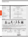
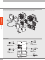
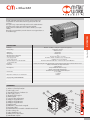
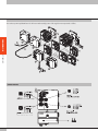
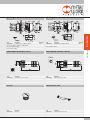
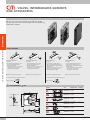
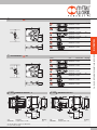
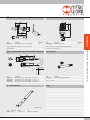
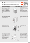
DISTRIBUTORS
FIELDBUS
CM CLEVER MULTIMACH
1
INTRODUCTION
GENERAL TECHNICAL DATA
Valve port connections
INTRODUCTION
DISTRIBUTORS
Ø 4,6,8 mm automatic fitting for ports 2 and 4 / power supply port for Ø10 automatic fitting /
3/8 thread for exhaust port / M5 thread for exhaust pilot port
Connection on the end-plate 1-11 for the supply of pilots
Automatic fitting Ø 4 mm
Maximum number of pilots
See input end-plate technical data
Maximum number of valves
See input end-plate technical data
Operating temperature range
°C
-10 to +60
Fluid
Filtered air without lubrication; lubrication, if used, must be continuous
Flow rate at 6.3 bar DP 1bar
Nl/min 11.5 mm Ø 4 11.5 mm Ø 6 14 mm Ø 8
version 5/2 and 3/2 200500650
version 5/3
200300300
Pressure range
X (pilot supply)
1-11 (valve supply)
end-plate 1-11 3 to 7 bar
vacuum at10 bar
end-plate 1
3 to 7 bar
Voltage range
24VDC ±10%
(slave protected against overload and reverse polarity)
Power for each pilot
W
0.9
Solenoid Pilot Insulation class
F155
Degree of protection
IP65 (with conveyed exhust, and that - in case of no use)
Diagnostics and protections
Local via PC/PLC fault led. For defects signalled look at the manual.
Outlets protected against overload and short-circuit
Solenoid rating
100% ED
Maximum latency time of the serial transmission
ms
,10
TRA/TRR 2x3/2 monostable at 6 bar
ms
8 / 45
TRA/TRR 5/2 monostable at 6 bar
ms
8 / 33
TRA/TRR 5/2 bistable at 6 bar
ms
20 / 20
TRA/TRR 5/3 cc monostable at 6 bar
ms
20 / 20
Note on use
Insert the pipes in the fittings, before passing air through the valves,
otherwise the gasket may be pulled out of its seat by the flow of air.
Compatibility with oils
Please refer to page 6-7 of the technical documentation of the general catalogue.
FIXING THE BASE
A Fixing from above using the 1 or 1-1 input end-plate and the blind end-plate.
B C Fixing from above using the 1 or 1-1 input end-plate and the blind end-plate, using the M5 threads on the bottom and the rear of the end-plates.
D Fixing from above using the 1 or 1-1 input end-plate and the blind end-plate, using the M5 threads on the front of the end-plates.
An opening for the pipes is made in the plate.
E Fixing on the DIN bar with end-plate 1 or 1-11 and blind end-plate, using the push-in bracket code 0227301600.
F Lateral fixing using the blind end-plate, and its the M4 threads on the side lateral.
Note: The sole fixing admitted is the one showed.
KEY TO CODES – CLEVER MULTIMACH
C M
VALVE
Clever
Multimach
2
2
PN O
INPUT END-PLATE
2
3
End-plate 1-11
End-plate 1
WITH FIELD BUS
FUNCTION
ADD
PN O
EC O
CAN O
Additional (slave) valves only
Profinet IO, outputs only
EtherCAT, outputs only
CANopen, outputs only
M
MANUAL TYPE
M
B
Monostable manual control
Bistable manual control
I6 - W8 - W6 - O4 - L8 - 5
16
TYPE OF VALVE
I
n° 2 3/2 NC
W n° 2 3/2 NO
L
3/2 NO + 3/2 NC
V 5/2 monostable
K 5/2 bistable
O 5/3 monostable
5 Blind end-plate
6Passing-intermede
7 Blind intermediate
20 Exhaust section
4 Cartridge 4
6 Cartridge 6
8 Cartridge 8
FURTHER DETAILS
16
n° 2 brackets for DIN bar
+ Profinet IO
DISTRIBUTORS
The CM + Profinet IO system has been designed with a pneumatic input endplate that can contain all the electronic equipment, indicators and connectors.
This system is very compact and sturdy and is housed in a thick aluminium
body that protects sensitive components from impact and falls.
At the moment it’s available the version suitable to handle up to 32 pilots
(32 Out).
Grounding is recommended to protect the electronic circuit against electric or
electrostatic charges.
TECHNICAL DATA
Factory settings
Addressing
Voltage range
Maximum number of pilots (Out)
Maximum number of valves
Icc bus supply current
Icc valve supply current
Maximum absorption of a valve island with
32 monostable valves
Protections
Connections
BUS diagnostics
Data bit value
Output status in the absence of communication
See page 2 for general technical data
Profinet IO - 100 Mbit/s - Full-duplex
Supports Fast Start Up, RT communication, Shared Device, Identification & Maintenance 1-4
Module name: Cmseries
Address IP 0.0.0.0
Software DCP
24VDC ± 10%
32
32 (same as the max. no. of pilotos)
Nominal Icc 120 mA - Instantaneous Icc (< 2 ms) 450 mA
Instantaneous Icc (< 2 ms) 450 mA
Nominal Icc with 450 mA OFF valves – nominal Icc with 1350 mA ON valves
CM + Profinet IO
Field buses
Module protected against overload and polarity reversal. Outputs protected against overloads and short-circuits
Field bus: 2 M12 Female, D-coded, internal switch
supply: M8 4 pin
Using local LEDs and software messages
Outputs: using local LEDs and status bytes
N.B. Refer to the user manual for a detailed description
0 = not enabled
1 = enabled
Disabled
COMPONENTS
a Exhaust - Solenoid pilot 82/84
b Valve supply - port 1
c Threaded connection of exhausts 3/5
d Valve supply - port 11
e Electrical control supply X
f Blind end-plate
g Screw for valve wall-mounting
h Utility port for pipe Ø 8 mm
i Utility port for pipe Ø 6 mm
j Utility port for pipe Ø 4 mm
k Manual control
l LED (LED on, solenoid valve energised)
m Pneumatic symbol
n Identification of the monostable or bistable manual control
o Valve ordering code
p Valve identification code
q Blank space for valve number
r CM Profinet IO end-plate
m
n
o
p
q
3
VALVE ISLAND CONFIGURATION
The numbers permit rapid identification of the function and assembly position of the single elements represented as follows.
5
DISTRIBUTORS
5
23
2
ADD
1
3
ADD
16
23
CM + Profinet IO
6
20
2
O
7
3
O
16
WIRING DIAGRAM
4
Code
Description
0227302230
End-plate CM 1-11 Profinet IO OUTPUT
This end-plate allows for supplies to be differentiated:
port 2, port 4 and pilot supply
Note: terminator included
M8 CONNECTOR FOR POWER SUPPLY
Weight [g]
683
Code
0227302231
END-PLATE 1 Profinet IO OUTPUT
Description
End-plate CM 1 Profinet IO OUTPUT
DISTRIBUTORS
3-O
END-PLATE 1-11 Profinet IO OUTPUT
Weight [g]
686
Note: terminator included
CM + Profinet IO
2-O
M12 PLUG
Pin Cable colour
1brown
2white
3blue
4black
Code
0240009037
Description
M8 connector for power supply wire 5 m
Code
0240009040
M12 BUS CONNECTOR, D-CODED
BUS CABLE
Code
0240005051
Code
0240005220
Description
M12 BUS connector, D-coded
Description
Plug M12
Description
BUS cable
Note: Can be used for BUS units in the EtherNet family (Profinet IO, EtherCAT, EtherNet/IP….)
5
DISTRIBUTORS
CM + Profinet IO
STRAIGHT BUS CONNECTOR
RJ45 CONNECTOR
Code
Description
0240005103
Straight connector for M12 BUS, D-coded, with 3m cable
0240005105
Straight connector for M12 BUS, D-coded, with 5m cable
0240005110
Straight connector for M12 BUS, D-coded, with 10m cable
Note: Can be used for BUS units in the EtherNet family (Profinet IO, EtherCAT, EtherNet/IP….)
Code
0240005050
NOTES
6
Description
RJ45 connector with 4 contacts according to IEC 60 603-7
+ EtherCAT
DISTRIBUTORS
The CM + EtherCAT system has been designed with a pneumatic input
end-plate that can contain all the electronic equipment, indicators and
connectors.
This system is very compact and sturdy and is housed in a thick aluminium
body that protects sensitive components from impact and falls.
At the moment it’s available the version suitable to handle up to 32 pilots
(32 Out).
Grounding is recommended to protect the electronic circuit against electric or
electrostatic charges.
TECHNICAL DATA
Field buses
Factory settings
BUS diagnostics
Data bit value
Output status in the absence of communication
CM + EtherCAT
Addressing
Voltage range
Maximum number of pilots (Out)
Maximum number of valves
Icc bus supply current
Icc valve supply current
Maximum absorption of a valve island with
32 monostable valves
Protections
Connections
EtherCAT - 100 Mbit/s - Full-duplex - Supports auto-negotiation
Module name: Cmseries
Address IP 0.0.0.0
Software DCP
24VDC ± 10%
32
32 (same as the max. no. of pilotos)
Nominal Icc 120 mA - Instantaneous Icc (< 2 ms) 450 mA
Instantaneous Icc (< 2 ms) 450 mA
Nominal Icc with 450 mA OFF valves – nominal Icc with 1350 mA ON valves
Module protected against overload and polarity reversal. Outputs protected against overloads and short-circuits
Field bus: 2 M12 Female, D-coded, internal switch
supply: M8 4 pin
Using local LEDs and software messages
Outputs: using local LEDs and status bytes
N.B. Refer to the user manual for a detailed description
0 = not enabled
1 = enabled
Disabled
See page 2 for general technical data
COMPONENTS
a Exhaust - Solenoid pilot 82/84
b Valve supply - port 1
c Threaded connection of exhausts 3/5
d Valve supply - port 11
e Electrical control supply X
f Blind end-plate
g Screw for valve wall-mounting
h Utility port for pipe Ø 8 mm
i Utility port for pipe Ø 6 mm
j Utility port for pipe Ø 4 mm
k Manual control
l LED (LED on, solenoid valve energised)
m Pneumatic symbol
n Identification of the monostable or bistable manual control
o Valve ordering code
p Valve identification code
q Blank space for valve number
r CM EtherCAT end-plate
m
n
o
p
q
7
VALVE ISLAND CONFIGURATION
The numbers permit rapid identification of the function and assembly position of the single elements represented as follows.
5
DISTRIBUTORS
5
23
2
ADD
1
3
ADD
16
23
CM + EtherCAT
6
20
2
O
7
3
O
16
WIRING DIAGRAM
8
Code
Description
0227302234
End-plate CM 1-11 EtherCAT OUTPUT
This end-plate allows for supplies to be differentiated:
port 2, port 4 and pilot supply
Note: terminator included
M8 CONNECTOR FOR POWER SUPPLY
Weight [g]
683
Code
0227302235
END-PLATE 1 EtherCAT OUTPUT
Description
End-plate CM 1 EtherCAT OUTPUT
DISTRIBUTORS
3-O
END-PLATE 1-11 EtherCAT OUTPUT
Weight [g]
686
Note: terminator included
CM + EtherCAT
2-O
M12 PLUG
Pin Cable colour
1brown
2white
3blue
4black
Code
0240009037
Description
M8 connector for power supply wire 5 m
Code
0240009040
M12 BUS CONNECTOR, D-CODED
BUS CABLE
Code
0240005051
Code
0240005220
Description
M12 BUS connector, D-coded
Description
Plug M12
Description
BUS cable
Note: Can be used for BUS units in the EtherNet family (Profinet IO, EtherCAT, EtherNet/IP….)
9
DISTRIBUTORS
CM + EtherCAT
10
STRAIGHT BUS CONNECTOR
RJ45 CONNECTOR
Code
Description
0240005103
Straight connector for M12 BUS, D-coded, with 3m cable
0240005105
Straight connector for M12 BUS, D-coded, with 5m cable
0240005110
Straight connector for M12 BUS, D-coded, with 10m cable
Note: Can be used for BUS units in the EtherNet family (Profinet IO, EtherCAT, EtherNet/IP….)
Code
0240005050
NOTES
Description
RJ45 connector with 4 contacts according to IEC 60 603-7
+ CANopen
DISTRIBUTORS
The CM+CANopen system has been designed with a pneumatic input
end-plate that can contain all the electronic equipment, indicators and
connectors. This system is very compact and sturdy and is housed in a thick
aluminium body that protects sensitive components impact and falls.
At the moment it’s available the version suitable to handle up to 32 pilots
(32 Out).
Grounding is recommended to protect the electronic circuit against electric or
electrostatic charges.
TECHNICAL DATA
Field buses
Factory settings
BUS diagnostics
Data bit value
Output status in the absence of communication
CM + CANopen
Addressing
Voltage range
Maximum number of pilots (Out)
Maximum number of valves
Icc bus supply current
Icc valve supply current
Maximum absorption of a valve island with
32 monostable valves
Protections
Connections
CANopen - Complies with CiA DS401 specifications
Module name: Cmseries
Address 4
Hardware via dip Switch
24VDC ± 10%
32
32 (same as the max. no. of pilotos)
Nominal Icc 30 mA - Instantaneous Icc (< 5 ms) 640 mA
Instantaneous Icc (< 5 ms) 500 mA
Nominal Icc with 450 mA OFF valves – nominal Icc with 1350 mA ON valves
Module protected against overload and polarity reversal. Outputs protected against overloads and short-circuits
Field bus: M12 Male inputs, 5 pins, A-coded; M12 Female outputs, 5 poles, A-coded
supply: M8 4 pin
Using local LEDs and software messages
Outputs: using local LEDs and status bytes
N.B. Refer to the user manual for a detailed description
0 = not enabled
1 = enabled
Disabled
See page 2 for general technical data
COMPONENTS
a Exhaust - Solenoid pilot 82/84
b Valve supply - port 1
c Threaded connection of exhausts 3/5
d Valve supply - port 11
e Electrical control supply X
f Blind end-plate
g Screw for valve wall-mounting
h Utility port for pipe Ø 8 mm
i Utility port for pipe Ø 6 mm
j Utility port for pipe Ø 4 mm
k Manual control
l LED (LED on, solenoid valve energised)
m Pneumatic symbol
n Identification of the monostable or bistable manual control
o Valve ordering code
p Valve identification code
q Blank space for valve number
r CM CANopen end-plate
m
n
o
p
q
11
VALVE ISLAND CONFIGURATION
CM + CANopen
DISTRIBUTORS
The numbers permit rapid identification of the function and assembly position of the single elements represented as follows.
WIRING DIAGRAM
(Female connector M12 A-coded)
(Male connector M12 A-coded)
12
Code
Description
0227302238
End-plate CM 1-11 CANopen OUTPUT
This end-plate allows for supplies to be differentiated:
port 2, port 4 and pilot supply
Note: terminator included
Weight [g]
678
Code
0227302239
END-PLATE 1 CANopen OUTPUT
Description
End-plate CM 1 CANopen OUTPUT
Note: terminator included
FEMALE CONNECTOR FOR CANopen BUS-IN
MALE CONNECTOR FOR CANopen BUS-OUT
Code
0240009055
Code
0240009038
Description
M12 female connector, A-coded
M12 PLUG
Code
0240009040
Weight [g]
680
DISTRIBUTORS
3-O
END-PLATE 1-11 CANopen OUTPUT
CM + CANopen
2-O
Description
Male connector Bus A-coded
CABLE FOR CANopen BUS
Description
Plug M12
Code
0240005250
Description
Cable for CANopen bus 20 mt
13
- VALVES, INTERMEDIATES ELEMENTS
AND ACCESSORIES
DISTRIBUTORS
CM valve can be included in islands with any available input terminal.
The same valve can be connected to the multiple connection end-plate and
all the field bus end-plates.
CM - VVALVES, INTERMEDIATES ELEMENTS AND ACCESSORIES
MANUAL CONTROLS
MONOSTABLE OVERRIDE PORT 2
servo-assisted
BISTABLE OVERRIDE PORT 2
servo-assisted
• Press and hold the manual control in position
(not necessary for bistable type K valve)
• Release the manual control:
- The manual control returns to the home position.
- Valves type I, W, L, V and O reposition.
- The type K valve remains switched
MONOSTABLE OVERRIDE PORT 4
servo-assisted
• Press and hold the manual control in position
(not necessary for bistable type K valve)
• Release the manual control:
- The manual control returns to the home position.
- Valves type I, W, L, V and O reposition.
- The type K valve remains switched
• Press the manual control right in then turn it
clockwise 90 degrees and Leave it in position.
• Rotate the manual control 90 degrees anticlockwise, and then release it.
- The manual control returns to the home position.
- Valves type I, W, L, V and O reposition.
- The type K valve remains switched
BISTABLE OVERRIDE PORT 4
servo-assisted
• Press the manual control right in then turn it 90 degrees clockwise and Leave it in position.
• Rotate the manual control 90 degrees anticlockwise, and then release it:
- The manual control returns to the home position.
- Valves type I, W, L and O reposition.
- The type K valve remains switched
N.B.: The pilot power supply X must be present.
N.B.: The pilot power supply X must be present.
N.B.: The pilot power supply X must be present.
N.B.: The pilot power supply X must be present.
• The reference code for the monostable control ends in “0”.
• The reference code for the monostable control ends in “1”.
Example: 707403053
Example: 707403053
a VALVE DIMENSIONS
Ø4
Symbol
I4
W4
L4
V4
K4
O4
14
Code
7074030530
7074030531
Manual control
monostable
bistable
Weight [g]
130
7074030630
7074030631
monostable
bistable
130
7074030730
7074030731
monostable
bistable
130
7074030130
7074030131
monostable
bistable
115
7074030110
7074030111
monostable
bistable
130
7074030210
7074030211
monostable
bistable
130
Symbol
I6
W6
L6
V6
K6
O6
a VALVE DIMENSIONS
I8
W8
L8
V8
K8
O8
Code
0227302224
Manual control
monostable
bistable
Weight [g]
130
7075030630
7075030631
monostable
bistable
130
7075030730
7075030731
monostable
bistable
130
7075030130
7075030131
monostable
bistable
115
7075030110
7075030111
monostable
bistable
130
7075030210
7075030211
monostable
bistable
130
Code
7076030530
7076030531
Manual control
monostable
bistable
Weight [g]
140
7076030630
7076030631
monostable
bistable
140
7076030730
7076030731
monostable
bistable
140
7076030130
7076030131
monostable
bistable
130
7076030110
7076030111
monostable
bistable
140
7076030210
7076030211
monostable
bistable
140
Ø8
Symbol
2 - ADD
Code
7075030530
7075030531
3 - ADD
ADDITIONAL END-PLATE 1-11
Description
End-plate CM kit 1-11 ADD
Weight [g]
770
Code
0227302226
DISTRIBUTORS
Ø6
CM - VVALVES, INTERMEDIATES ELEMENTS AND ACCESSORIES
a VALVE DIMENSIONS
ADDITIONAL END-PLATE 1
Description
End-plate CM kit 1 ADD
Weight [g]
770
This end-plate allows for supplies to be differentiated:
port 2, port 4 and pilot supply
15
CM - VVALVES, INTERMEDIATES ELEMENTS AND ACCESSORIES
DISTRIBUTORS
WIRING DIAGRAM FOR THE ADDITIONAL TERMINAL
a Indicator LED
bGrounding
e BLIND EN-PLATE
Code
0227302500
Description
Blind en-plate CM
f INTERMEDIATE THROUGHT
Weight [g]
230
g INTERMEDIATE BLIND
Code
0227302302
16
Description
Intermediate blind CM
Code
0227302301
Description
Intermediate throught CM
Weight [g]
120
t INTERMEDIATE EXHAUST SWITCH
Weight [g]
117
Code
0227302303
Description
Intermediate exhaust switch CM
Weight [g]
125
p CONNECTION BRACKETS ON DIN BAR
Description
Connection brackets on din bar HDM/CM
Weight [g]
30
Code
W0970530084
Description
Silencer for fitting, Ø 8
Weight [g]
15
At the 3/5-exhaust port of the intermediate through reference 6
and the exhaust switch reference 20
u
23 M8 PREWIRED CONNECTOR FOR VALVE ISLANDS CONNECTIONS
GRUB SCREW KIT
CM - VVALVES, INTERMEDIATES ELEMENTS AND ACCESSORIES
Supplied complete with one M4x45 screws and one grub screw
Individually packed
Pin Cable colour
1Brown
2White
3Blue
4Black
Code
0240005003
0240005005
0240005006
0240005008
Description
M8 prewired connector for valve islands conn. CM L = 5 m
M8 prewired connector for valve islands conn. CM L = 1 m
M8 prewired connector for valve islands conn. CM L = 3 m
M8 prewired connector for valve islands conn. CM L = 10 m
R17 - DISASSEMBLY KEY
Code
0227301800
DISTRIBUTORS
Code
0227301600
SILENCER FOR FITTING, Ø 8
Description
Grub screw for Multimach HDM/CM
Comes 1 + 1 packs
NOTES
Lenght = 140 mm
Code
2L17001
Description
RL17
www.metalwork.eu
Ø Tube
from Ø 3 to Ø 10
Tube
For R fitting and Fox fitting
Dimensions and data shown in this catalogue are subject to variations at any time without prior notice
MNWS02064_GB - IM00_10/2014
17