1
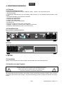
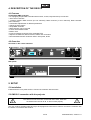
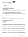
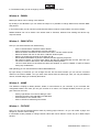
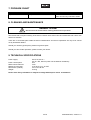
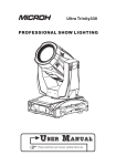
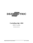
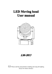
BEDIENUNGSANLEITUNG
USER MANUAL
DMD-512
DMX-controller
Für weiteren Gebrauch aufbewahren!
Keep this manual for future needs!
© Copyright
Nachdruck verboten!
Reproduction prohibited!
Inhaltsverzeichnis
Table of contents
1. EINFÜHRUNG ............................................................................................................................................... 3
2. SICHERHEITSHINWEISE............................................................................................................................. 3
3. BESTIMMUNGSGEMÄßE VERWENDUNG................................................................................................. 4
4. GERÄTEBESCHREIBUNG........................................................................................................................... 5
5. SETUP ........................................................................................................................................................... 5
6. BEDIENUNG ................................................................................................................................................. 6
7. PROBLEMBEHEBUNG ................................................................................................................................ 6
8. REINIGUNG UND WARTUNG...................................................................................................................... 6
9. TECHNISCHE DATEN .................................................................................................................................. 7
1. INTRODUCTION ........................................................................................................................................... 8
2. SAFETY INSTRUCTIONS ............................................................................................................................ 8
3. OPERATING DETERMINATIONS................................................................................................................ 9
4. DESCRIPTION OF THE DEVICE ............................................................................................................... 10
5. SETUP ......................................................................................................................................................... 10
6. OPERATION ............................................................................................................................................... 11
7. PROBLEM CHART ..................................................................................................................................... 16
8. CLEANING AND MAINTENANCE ............................................................................................................. 16
9. TECHNICAL SPECIFICATIONS................................................................................................................. 16
Diese Bedienungsanleitung gilt für die Artikelnummer 51834650
This user manual is valid for the article number 51834650
Das neueste Update dieser Bedienungsanleitung finden Sie im Internet unter:
You can find the latest update of this user manual in the Internet under:
www.futurelight.com
2/16
00033923.DOC, Version 1.0
BEDIENUNGSANLEITUNG
DMD-512
DMX-controller
Lesen Sie vor der ersten Inbetriebnahme zur eigenen Sicherheit diese Bedienungsanleitung
sorgfältig durch!
Alle Personen, die mit der Aufstellung, Inbetriebnahme, Bedienung, Wartung und Instandhaltung dieses
Gerätes zu tun haben, müssen
- entsprechend qualifiziert sein
- diese Bedienungsanleitung genau beachten
- die Bedienungsanleitung als Teil des Produkts betrachten
- die Bedienungsanleitung während der Lebensdauer des Produkts behalten
- die Bedienungsanleitung an jeden nachfolgenden Besitzer oder Benutzer des Produkts weitergeben
- sich die letzte Version der Anleitung im Internet herunter laden
1. EINFÜHRUNG
Wir freuen uns, dass Sie sich für einen FUTURELIGHT DMD-512 entschieden haben. Wenn Sie
nachfolgende Hinweise beachten, sind wir sicher, dass Sie lange Zeit Freude an Ihrem Kauf haben werden.
Nehmen Sie den DMD-512 aus der Verpackung.
2. SICHERHEITSHINWEISE
Dieses Gerät hat das Werk in sicherheitstechnisch einwandfreiem Zustand verlassen. Um diesen Zustand zu
erhalten und einen gefahrlosen Betrieb sicherzustellen, muss der Anwender unbedingt die Sicherheitshinweise und die Warnvermerke beachten, die in dieser Bedienungsanleitung enthalten sind.
Unbedingt lesen:
Bei Schäden, die durch Nichtbeachtung dieser Bedienungsanleitung verursacht werden, erlischt der
Garantieanspruch. Für daraus resultierende Folgeschäden übernimmt der Hersteller keine Haftung.
Bitte überprüfen Sie vor der ersten Inbetriebnahme, ob kein offensichtlicher Transportschaden vorliegt.
Sollten Sie Schäden am Netzteil oder am Gehäuse entdecken, nehmen Sie das Gerät nicht in Betrieb und
setzen sich bitte mit Ihrem Fachhändler in Verbindung.
Das Netzteil immer als letztes einstecken.
Halten Sie das Gerät von Hitzequellen wie Heizkörpern oder Heizlüftern fern.
3/16
00033923.DOC, Version 1.0
Das Gerät darf nicht in Betrieb genommen werden, nachdem es von einem kalten in einen warmen Raum
gebracht wurde. Das dabei entstehende Kondenswasser kann unter Umständen Ihr Gerät zerstören. Lassen
Sie das Gerät solange uneingeschaltet, bis es Zimmertemperatur erreicht hat!
Der Aufbau entspricht der Schutzklasse III. Das Gerät darf niemals ohne einen geeigneten Transformator
betrieben werden.
Gerät bei Nichtbenutzung und vor jeder Reinigung vom Netz trennen.
Beachten Sie bitte, dass Schäden, die durch manuelle Veränderungen an diesem Gerät verursacht werden,
nicht unter den Garantieanspruch fallen.
Kinder und Laien vom Gerät fern halten!
Im Geräteinneren befinden sich keine zu wartenden Teile. Eventuelle Servicearbeiten sind ausschließlich
dem autorisierten Fachhandel vorbehalten!
3. BESTIMMUNGSGEMÄßE VERWENDUNG
Bei diesem Gerät handelt es sich um einen DMX-Controller, mit dem sich DMX-gesteuerte Lichteffekte,
Scheinwerfer etc. in Diskotheken, auf Bühnen etc. ansteuern lassen. Dieses Produkt ist für den Anschluss
an DC 9-12 V, 500 mA Gleichspannung zugelassen und wurde ausschließlich zur Verwendung in
Innenräumen konzipiert.
Vermeiden Sie Erschütterungen und jegliche Gewaltanwendung bei der Installation oder Inbetriebnahme des
Gerätes.
Achten Sie bei der Wahl des Installationsortes darauf, dass das Gerät nicht zu großer Hitze, Feuchtigkeit
und Staub ausgesetzt wird. Vergewissern Sie sich, dass keine Kabel frei herumliegen. Sie gefährden Ihre
eigene und die Sicherheit Dritter!
Das Gerät darf nicht in einer Umgebung eingesetzt oder gelagert werden, in der mit Spritzwasser, Regen,
Feuchtigkeit oder Nebel zu rechnen ist. Feuchtigkeit oder sehr hohe Luftfeuchtigkeit kann die Isolation
reduzieren und zu tödlichen Stromschlägen führen. Beim Einsatz von Nebelgeräten ist zu beachten, dass
das Gerät nie direkt dem Nebelstrahl ausgesetzt ist und mindestens 0,5 m von einem Nebelgerät entfernt
betrieben wird. Der Raum darf nur so stark mit Nebel gesättigt sein, dass eine gute Sichtweite von
mindestens 10 m besteht.
Die Umgebungstemperatur muss zwischen -5° C und +45° C liegen. Halten Sie das Gerät von direkter
Sonneneinstrahlung (auch beim Transport in geschlossenen Wägen) und Heizkörpern fern.
Die relative Luftfeuchte darf 50 % bei einer Umgebungstemperatur von 45° C nicht überschreiten.
Dieses Gerät darf nur in einer Höhenlage zwischen -20 und 2000 m über NN betrieben werden.
Verwenden Sie das Gerät nicht bei Gewitter. Überspannung könnte das Gerät zerstören. Das Gerät bei
Gewitter allpolig vom Netz trennen (Netzstecker ziehen).
Nehmen Sie das Gerät erst in Betrieb, nachdem Sie sich mit seinen Funkionen vertraut gemacht haben.
Lassen Sie das Gerät nicht von Personen bedienen, die sich nicht mit dem Gerät auskennen. Wenn Geräte
nicht mehr korrekt funktionieren, ist das meist das Ergebnis von unfachmännischer Bedienung!
Soll das Gerät transportiert werden, verwenden Sie bitte die Originalverpackung, um Transportschäden zu
vermeiden.
Beachten Sie bitte, dass eigenmächtige Veränderungen an dem Gerät aus Sicherheitsgründen verboten
sind.
Der Serienbarcode darf niemals vom Gerät entfernt werden, da ansonsten der Garantieanspruch erlischt.
Wird das Gerät anders verwendet als in dieser Bedienungsanleitung beschrieben, kann dies zu Schäden am
Produkt führen und der Garantieanspruch erlischt. Außerdem ist jede andere Verwendung mit Gefahren, wie
z. B. Kurzschluss, Brand, elektrischem Schlag, etc. verbunden.
4/16
00033923.DOC, Version 1.0
4. GERÄTEBESCHREIBUNG
4.1 Features
Komfortabler DMX-Monitortreiber
• Versorgt einfache DMX-Steuerungen mit Monitor, Maus-, Tastatur- und Computeranschluss
• 1024 Steuerkanäle
• 3 Arbeitsmodi: DMX Receiver (2x 512 Kanäle), DMX Converter (1x 512 Kanäle), DMX Controller (1024
Kanäle)
• Komfortable Einstellung verschiedener Parameter
• Veränderung der Kanalwerte
• Gruppieren der DMX-Kanäle
• Invertieren der DMX-Kanäle
• Erstellen eines virtuellen Masterfaders
• Eingebaute Uhr
• Eingänge: 2x DMX-512, Maus PS/2, Tastatur PS/2
• Ausgänge: 2x DMX-512, Monitor SVGA, USB für PC-Anschluss
• Empfohlene Monitorauflösung 1280 x 1024 Pixel, 60 Hz
4.2 Geräteübersicht
Übersicht über die Bedienelemente
Rückseite:
5. SETUP
5.1 Installation
Stellen Sie das Gerät auf einer ebenen Fläche auf. Schließen Sie das Gerät ans Netz an.
5.2 Anschluss an den Projektor
Achten Sie darauf, dass die Adern der Datenleitung an keiner
Stelle miteinander in Kontakt treten. Die Geräte werden
ansonsten nicht bzw. nicht korrekt funktionieren.
Die Verbindung zwischen Controller und Projektor sowie zwischen den einzelnen Geräten muss mit einem
zweipoligen geschirmten Kabel erfolgen. Die Steckverbindung geht über 3-polige XLR-Stecker und -Kupplungen.
5/16
00033923.DOC, Version 1.0
Belegung der XLR-Verbindung:
Wenn Sie die empfohlenen FUTURELIGHT-Projektoren verwenden, können Sie den DMX-Ausgang des
Controllers direkt mit dem DMX-Eingang des ersten Gerätes der DMX-Kette verbinden. Sollen Projektoren
mit anderen DMX-Ausgängen angeschlossen werden, müssen Adapterkabel verwendet werden.
Aufbau einer seriellen DMX-Kette:
Verbinden Sie den DMX-Ausgang des DMD-512 mit dem DMX-Eingang des nächsten Gerätes. Verbinden
Sie immer einen Ausgang mit dem Eingang des nächsten Gerätes bis alle Geräte angeschlossen sind.
Achtung: Am letzten Projektor muss die DMX-Leitung durch einen Abschlusswiderstand abgeschlossen
werden. Dazu wird ein 120 Widerstand in einen XLR-Stecker zwischen Signal (–) und Signal (+) eingelötet
und in den DMX-Ausgang am letzten Gerät gesteckt.
6. BEDIENUNG
Der Controller nimmt den Betrieb auf sobald Sie die Spannungsversorgung herstellen.
Bitte führen Sie immer zuerst einen Software-Update auf die neueste Version durch.
Bitte beachten Sie die Menübeschreibung im englischen Teil dieser Anleitung.
7. PROBLEMBEHEBUNG
PROBLEM:
Gerät lässt sich nicht anschalten.
URSACHE:
Die Anschlussleitung des Netzteils
ist nicht angeschlossen.
LÖSUNG:
Überprüfen Sie die
Anschlussleitung und eventuelle
Verlängerungsleitungen.
8. REINIGUNG UND WARTUNG
Das Gerät sollte regelmäßig von Verunreinigungen wie Staub usw. gereinigt werden. Verwenden Sie zur
Reinigung ein fusselfreies, angefeuchtetes Tuch. Auf keinen Fall Alkohol oder irgendwelche Lösungsmittel
zur Reinigung verwenden!
Im Geräteinneren befinden sich keine zu wartenden Teile. Wartungs- und Servicearbeiten sind ausschließlich dem autorisierten Fachhandel vorbehalten!
Sollten einmal Ersatzteile benötigt werden, verwenden Sie bitte nur Originalersatzteile.
Sollten Sie noch weitere Fragen haben, steht Ihnen Ihr Fachhändler jederzeit gerne zur Verfügung.
6/16
00033923.DOC, Version 1.0
9. TECHNISCHE DATEN
Spannungsversorgung:
Gesamtanschlusswert:
DMX-Steuerkanäle:
DMX 512-Anschluss:
Maße (LxBxH):
Gewicht:
230 V AC, 50 Hz ~
über mitgeliefertes 12 V DC, 500 mA Netzteil
6W
1024
3-pol. XLR, 2x IN, 2x OUT
315 x 75 x 68 mm
0,75 kg
Bitte beachten Sie: Technische Änderungen ohne vorherige Ankündigung und Irrtum vorbehalten.
07.03.2008 ©
7/16
00033923.DOC, Version 1.0
USER MANUAL
DMD-512
DMX-controller
CAUTION!
Keep this device away from rain and moisture!
Unplug mains lead before opening the housing!
For your own safety, please read this user manual carefully before you initially start-up.
Every person involved with the installation, operation and maintenance of this device has to
- be qualified
- follow the instructions of this manual
- consider this manual to be part of the total product
- keep this manual for the entire service life of the product
- pass this manual on to every further owner or user of the product
- download the latest version of the user manual from the Internet
1. INTRODUCTION
Thank you for having chosen a FUTURELIGHT DMD-512. If you follow the instructions given in this manual,
we are sure that you will enjoy this device for a long period of time.
Unpack your DMD-512.
2. SAFETY INSTRUCTIONS
This device has left our premises in absolutely perfect condition. In order to maintain this condition and to
ensure a safe operation, it is absolutely necessary for the user to follow the safety instructions and warning
notes written in this user manual.
Important:
Damages caused by the disregard of this user manual are not subject to warranty. The dealer will
not accept liability for any resulting defects or problems.
Please make sure that there are no obvious transport damages. Should you notice any damages on the
power unit or on the casing, do not take the device into operation and immediately consult your local dealer.
Always plug in the power unit least.
Keep away from heaters and other heating sources!
8/16
00033923.DOC, Version 1.0
If the device has been exposed to drastic temperature fluctuation (e.g. after transportation), do not switch it
on immediately. The arising condensation water might damage your device. Leave the device switched off
until it has reached room temperature.
This device falls under protection-class III. The device always has to be operated with an appropriate
transformer.
Always disconnect from the mains, when the device is not in use or before cleaning it.
Please note that damages caused by manual modifications on the device or unauthorized operation by
unqualified persons are not subject to warranty.
Keep away children and amateurs from the device!
There are no serviceable parts inside the device. Maintenance and service operations are only to be carried
out by authorized dealers.
3. OPERATING DETERMINATIONS
This device is a DMX-controller for controlling DMX-effects or spots in discotheques, on stages etc. This
product is allowed to be operated with a direct voltage of DC 9-12 V, 500 mA and was designed for indoor
use only.
Do not shake the device. Avoid brute force when installing or operating the device.
When choosing the installation-spot, please make sure that the device is not exposed to extreme heat,
moisture or dust. There should not be any cables lying around. You endanger your own and the safety of
others!
This device must never be operated or stockpiled in sourroundings where splash water, rain, moisture or fog
may harm the device. Moisture or very high humidity can reduce the insulation and lead to mortal electrical
shocks. When using smoke machines, make sure that the device is never exposed to the direct smoke jet
and is installed in a distance of 0.5 meters between smoke machine and device. The room must only be
saturated with an amount of smoke that the visibility will always be more than 10 meters.
The ambient temperature must always be between -5° C and +45° C. Keep away from direct insulation
(particularly in cars) and heaters.
The relative humidity must not exceed 50 % with an ambient temperature of 45° C.
This device must only be operated in an altitude between -20 and 2000 m over NN.
Never use the device during thunderstorms. Over voltage could destroy the device. Always disconnect the
device during thunderstorms.
Operate the device only after having familiarized with its functions. Do not permit operation by persons not
qualified for operating the device. Most damages are the result of unprofessional operation!
Please use the original packaging if the device is to be transported.
Please consider that unauthorized modifications on the device are forbidden due to safety reasons!
Never remove the serial barcode from the device as this would make the guarantee void.
If this device will be operated in any way different to the one described in this manual, the product may suffer
damages and the guarantee becomes void. Furthermore, any other operation may lead to dangers like shortcircuit, burns, electric shock, etc.
9/16
00033923.DOC, Version 1.0
4. DESCRIPTION OF THE DEVICE
4.1 Features
Comfortable DMX-controller
• For equipping simple DMX-controllers with monitor, mouse, keyboard and pc connection
• 1024 control channels
• 3 working modes: DMX receiver (2x 512 channels), DMX converter (1x 512 channels), DMX controller
(1024 channels)
• Comfortable adjustement of different parameters
• Change channel values
• Group DMX-channels
• DMX-channels can be inverted
• Include virtual Master Fader
• Built-in clock
• Inputs: 2x DMX-512, Mouse PS/2, Keyboard PS/2
• Outputs: 2x DMX-512, Monitor SVGA, USB for PC connection
• Recommended monitor resolution 1280 x 1024 pixels, 60 Hz
4.2 Overview
Overview on the control elements
Rear panel:
5. SETUP
5.1 Installation
Install the device on a plane surface. Connect the controller with the mains.
5.2 DMX-512 connection with the projector
The wires must not come into contact with each other, otherwise
the fixtures will not work at all, or will not work properly.
Only use a stereo shielded cable and 3-pin XLR-plugs and connectors in order to connect the controller with
the fixture or one fixture with another.
10/16
00033923.DOC, Version 1.0
Occupation of the XLR-connection:
If you are using the recommended FUTURELIGHT-controllers, you can connect the DMX-output of the
controller directly with the DMX-input of the first fixture in the DMX-chain. If you wish to connect DMXcontrollers with other DMX-outputs, you need to use adapter-cables.
Building a serial DMX-chain:
Connect the DMX-output of the DMD-512 with the DMX-input of the nearest projector. Always connect one
output with the input of the next fixture until all fixtures are connected.
resistor
Caution: At the last fixture, the DMX-cable has to be terminated with a terminator. Solder a 120
between Signal (–) and Signal (+) into a 3-pin XLR-plug and plug it in the DMX-output of the last fixture.
6. OPERATION
The controller starts running as soon as you connect the power supply.
Please do always update this controller to the latest software version.
Introduction
DMX Monitor is able to visualize (receiver), convert (receiver and transmitter) and adjust (transmitter) DMX
channel values. Any kind of DMX Controller can be connected to DMX Monitor. On the screen not only DMX
values can be seeing, but the user can give a channel order, can give a name for channels. With help of
keyboard and mouse easy fast can be change all parameters.
Starting
At first start do not connect any DMX cable to device, because first should be set the working mode.
-
Connect a Monitor, any kind of monitor (CRT or LCD). It should work on 1280x1024 resolutions and
on 57,6Hz. Most of monitor can perform it, but strongly recommend trying monitor before buying it.
Connect any kind of keyboard with PS/2 socket to KEYBOARD connector
Connect any kind of mouse with PS/2 socket to MOUSE connector
Connect the power supply which is accessories for Product.
Connect the Monitor and Power supply to electric network
After some seconds the monitor will switched on, and you can see the screen.
Language setup
In upper-right part of display you can see the actual language setting (Gray letters). To change it click by left
mouse button on the actual setting. The ‘Language setup’ window will open.
-
Simply click on the wanted language. On actual setting marked with a small arrow on left side.
Click on SAVE button to save data and leave this window, or click on CANCEL to leave it without
saving any modifications.
11/16
00033923.DOC, Version 1.0
Time setup
In upper-right corner you can see the time. If this is not correct, or device first time started, you have to set it.
-
Move the mouse cursor above the time
Click by left mouse button – The ‘Time setup’ will open, and text cursor is blinking in hours field
Simply type the correct time (hours, min, and sec) by keyboard.
Click on SAVE button to save data and leave this window, or click on CANCEL to leave it without
saving any modifications.
Window selection
In lower line of the screen you can see the window names. Select menu by clicking mouse left button on
wanted window name.
-
1. Fixture: Installed fixture data on installed order.
2. Name: Any effect or event name can be write
3. DMX Patch: Patched fixture data
4. DMX In: Received DMX values
5. DMX Out: Transferred DMX values
8. Menu: Select menus
9. Game: Have a fun!
0. Time: Time with huge characters.
Window 0 – Time
You can see the time with large numbers. If it is not correct, see chapter ‘Time setup’.
Window 9 – Game
Simply game, later can be possible to load new one’s form website and load it to device by USB port. Have a
fun!
Window 8 – MENU
Additional setup possibilities. To select any menu click by left mouse button on the text.
-
1. Working mode
2. Unit library
3. Channels setup
4. Information
Window 8. – MENU – Information
You can read information about the product. Actual software version and date, production date and the serial
number of the product.
Compare the software version with the latest version on the homepage. If you can find a newer you can
download it to your PC and load to the DMX Monitor by USB.
To leave this window click on ‘Close’ button on the screen.
12/16
00033923.DOC, Version 1.0
Window 8 – MENU – Working mode
The device has three different working modes:
-
Receiver
Converter
Transmitter
Upper line of screen you can see DMX signal indicators. The left indicator is for A, and right indicator is for B
output. It has different colors: red, green, yellow.
S – Waiting for DMX signal, but no DMX signal received.
S – DMX signal is received.
S – DMX signal transmitting.
Receiver: Receive DMX signal on input A and B, the same signal appear on output A and B. The device can
visualize DMX values on monitor. (1024 channel mode).
Converter: Receive DMX signal on input A, the same signal appear on output A, Modified signal appear on
output B. In this case prohibit contacting any DMX cable on input B! (512 channel mode).
Transmitter: The device works as normal controller, DMX signal appear on output A and B. In this case
prohibit contacting any DMX cable on input A and B! (1024 channel mode).
Window 8 – MENU – Channel setup
You need this menu if you use the device in converter mode. In mode receiver and transmitter have no
effects.
For all input and output channels can be set different attributes. On the foot part you can see INPUT and
OUTPUT ears. By clicking mouse button you can choose one.
At the same time 10 channels parameters can be seeing. On the right side of the window there are two
arrows to step the channel number up and down.
Select input window
1. Column: In
Input channel numbers (1-512)
2. Column: Thru
If checked, then this input channel will appear on the output and you can configure other parameters in this
row.
3. Column: Out
Output channel number. The input channel which is now edited will appear on the output channel which will
you write here.
4. Column: Min
Minimum value for the channel. Here you can to restrict the channel value, if the input value is less then
minimum value, then the minimum value will be sent to output.
5. Column: Max
Maximum value for the channel. Here you can to restrict the channel value, if the input value is higher then
maximum value, then the maximum value will be send to output.
6. Column: Comp
If compress is checked, then the input value will be compressed to output between minimum and maximum
value.
13/16
00033923.DOC, Version 1.0
Example: If Min=150 and Max=200, then the input value 0-255 will compressed between 150 and 200, so if
input = 127, then output = 175.
7. Column: Rev
If reverse is checked, then the input value will be reversed on output.
8. Column: 16bit
If the input channel is a part of 16 bit channel and the higher byte, then check it.
9. Column: Fine
You can edit if this channel is a 16 bit higher byte. Set the number how far is the lower part of the 16 bit
effect.
Example: If PAN and PANFINE channels are after the other, then set the fine value 1.
In output window you can set the same parameters as in input window. You need to set any output channel if
you like to control with one input channels more output channels.
For example: You have 8 moving heads. You controller has not GRAND MASTER slider. You have to
configure in your mixer one channel which you can change with a slider. Take it to DMX address 100. Now
select in DMX Monitor the output window, set the dimmer channels for your moving heads, and write to IN
column number 100. In this case if you modify the 100 channel in your mixer, then all the dimmer will be
change. So you add a GRAND MASTER function to you r mixer with help of DMX Monitor.
Window 8 – MENU – Unit library
Here you can define projector data.
Make a new projector click on NEW button. The window ‘Unit library – Edit’ will open.
Edit an existing projector select its Manufacturer by clicking on the name. The selected manufacturer units
list appear. Select the fixtures which want to edit by click on the name. The window ‘Unit library – Edit’ will
open.
Name:
Fixture name, max. 16 characters. Click by mouse and type by keyboard the name.
Manufacturer:
Manufacturer name, max. 16 characters. Click by mouse and type by keyboard the name.
Ch. Numbers:
Channel number of the fixture, max. 48 can be setup.
Channels name:
Name of channels, max 8 characters.
Channels order:
Here you can group the channels. The first column is the page number (1-12), and the second column is for
column number on act page. This setting is important if you use ‘1. FIXTURE’ window.
Click on SAVE button to save data and leave this window, or click on CANCEL to leave it without saving any
modifications.
Window 5 – DMXOUT
DMX output values can be seeing in this window.
By clicking A and B buttons you can select the output. It is possible to change data format, between DMX
and percent.
14/16
00033923.DOC, Version 1.0
In Transmitter mode you can change by mouse wheel any channel values.
Window 4 – DMXIN
DMX input values can be seeing in this window.
By clicking A and B buttons you can select the output. It is possible to change data format, between DMX
and percent.
In Converter mode you can not see input B channel values, because A input will be convert to B output.
DMXIN window can not be select if the actual mode is Transmit, because now working the device only
output channels.
Window 3 – DMX PATCH
Here you can select fixtures from fixture library.
-
Click on CLEAR button. All fixture will be deleted
Click on the first row: ‘Manufacturer’ window will opens
Select the fixture manufacturer and click on the name: ‘Unit list’ window opens
Select the fixture and click on the name: ‘Address’ window opens
Select A or B Output by clicking on the letter A or B
Set the DMX start address by click the address field and type it by keyboard
Set number of fixture. If you have more fixture, and they are addressed back to back, then here you
can set the number of this fixture, and automatically will all patched.
Click on SAVE button to save data and leave this window, or click on CANCEL to leave it without
saving any modifications.
After patching you can see the fixtures and its DMX addresses.
By right clicking of comment you can change the text. On the fixture window you can see the comment
values on the column ‘NAME’. So if you have more fixtures from the same type, here you can give different
names, and later helps you to identify the fixtures.
Window 2 – NAME
This window is helping to identify buttons, sliders, or other effects on you controller. If your controller has
configurable sliders, then here you can give a name for a column, for example SLIDER, and then you can
give names for the rows..
-
Click by right button of mouse for editing a name
Press Esc to leave name edit without modification
Press ENTER to save edited name
Click on CLEAR to delete all given names
Window 1 – FIXTURE
Here you can see the patched fixtures data. By clicking page numbers 1-12 you can select a page, and
always for columns can be seeing.
In transmitter mode possible to change channel value with mouse wheel in same way as in DMX output
window.
15/16
00033923.DOC, Version 1.0
7. PROBLEM CHART
PROBLEM:
No power.
CAUSE:
The power unit is not connected.
REMEDY:
Check the connection cable of the
power unit and any extension-cables.
8. CLEANING AND MAINTENANCE
DANGER TO LIFE!
Disconnect from mains before starting maintenance operation!
We recommend a frequent cleaning of the device. Please use a soft lint-free and moistened cloth. Never use
alcohol or solvents!
There are no servicable parts inside the device. Maintenance and service operations are only to be carried
out by authorized dealers.
Should you need any spare parts, please use genuine parts.
Should you have further questions, please contact your dealer.
9. TECHNICAL SPECIFICATIONS
Power supply:
Power consumption:
DMX-control-channels:
DMX-512-connection:
Dimensions (LxWxH):
Weight:
230 V AC, 50 Hz ~
via 12 V DC, 500 mA power unit included in the delivery
6W
1024
3-pin XLR, 2x In, 2x OUT
315 x 75 x 68 mm
0.75 kg
Please note: Every information is subject to change without prior notice. 07.03.2008 ©
16/16
00033923.DOC, Version 1.0