1
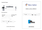
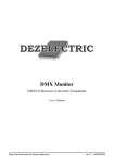
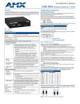
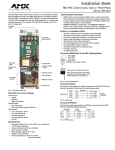
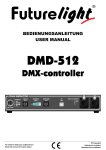
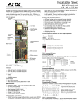
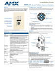
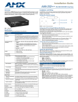
Installation Guide
AXB-DMX512 DMX512 Interface
Overview
Terminating the Device
The AXB-DMX512 DMX512 Interface (FG5927) creates a bi-directional DMX512
AXlink connection, transmitting and receiving up to 512 DMX channels for
lighting dimmers, spotlights, and other DMX control applications.
When using the DMX input and if this device is the last device in a chain of
DMX512 devices, you must terminate the line. To terminate the device, position
jumpers on jumper pin trios JP4 and JP5 (FIG. 2):
Onboard processing and memory can create and store channel groups, faders,
patches, and up to 72 presets. A DMX lighting board can operate in tandem with
the AXB-DMX512, generate levels for storing presets, or pass through the AXBDMX512 for direct control of channels.
JP5
Termination Jumpers
(JP4 / JP5)
JP4
DEVICE
AXlink
TX
RX
ON
Device ID DIP Switch
Axlink activity LED
DMX512 (Receive) LED
DMX512 (Transmit) LED
The DIP Switch located to the
right of the DEVICE DIP switch
is not used - no settings are
required, and any setting
will work.
FIG. 1 AXB-DMX512 (front view)
COR
Specifications
AXB-DMX512 Specifications
Power consumption
160 mA @ 12 VDC
Power supply
12 VDC
FIG. 2 Location of termination jumpers (JP4-JP5)
Enclosure
Metal with black matte finish
Mounting
Rack mounting with the optional AC-RK Accessory Rack
Kit
Weight
1.1 lb (0.5 kg)
IN
OUT
AXP
PWR
AXM
GND
DATA 2
1.5" x 5.5" x 5.5" (38 mm x 140 mm x 140 mm)
NC
Dimensions (HWD)
DATA 2
4-wire, captive-wire connector for data and power.
DATA 1
5-wire, captive-wire connector for transmitting data.
AXlink
The AXB-DMX512 has three captive-wire connectors on the rear panel (FIG. 4)
for DMX512 transmit and receive, and AXlink.
GND
DMXOUT port
Wiring Devices to the AXB-DMX512
DATA 1
5-wire, captive-wire connector for receiving data.
FIG. 3 Termination jumper pin settings for JP4 and JP5
DATA 2
DMXIN port
HIZ
NC
Rear panel components:
TERM
DATA 2
• 8-position DEVICE DIP switch sets the AXlink address
(Device ID) for the AXB-DMX512.
• The DIP Switch to the right of the DEVICE DIP is
reserved - no settings are required.
2.
Remove the jumper that is on pins 1 and 2 of jumper trios JP4 and JP5.
(Pins 1 and 2 are marked HIZ - see FIG. 3).
Place the jumper on pins 2 and 3 of jumper trios JP4 and JP5. (Pins 2 and
3 are marked TERM -see FIG. 3). This terminates the incoming DMX input
with a 120 ohm resistor.
DATA 1
DIP switch
1.
GND
• AXlink LED (green and blinks to indicate AXlink
communication activity and power:
Full-Off indicates no power is being received or the
controller is not functioning properly.
One blink per second indicates power is active and
AXlink communication is functioning.
Full-On indicates there is no AXlink control or activity,
but power is On.
• RX LED (red) indicates the AXB-DMX512 is receiving
DMX512 data. Corresponds to the IN and OUT ports
on the rear panel.
• TX LED (red) indicates the AXB-DMX512 is
transmitting DMX512 data. Corresponds to the IN and
OUT ports on the rear panel.
DATA 1
Front panel components:
LED Indicators
front
DEVICE DIP Switch
AXlink
FIG. 4 AXB-DMX512 (rear view)
Setting the Device DIP Switch
The 8-position DEVICE DIP switch on the front panel (FIG. 1) sets the AXlink
identification number for the AXB-DMX512. Make sure the device number
matches the number assigned in the Axcess software program.
The following table describes the values on the DEVICE DIP switch.
Device DIP Switch Settings
Preparing/connecting captive wires
1.
2.
Strip 0.25 inch of wire insulation off all wires.
Insert each wire into the appropriate opening on the connector according to
the wiring diagrams and connector types described in this section. Do not
tighten the screws excessively; doing so may strip the threads and damage
the connector.
Wiring guidelines
Position
1
2
3
4
5
6
7
8
Value
1
2
4
8
16
32
64
128
The interface requires a 12 VDC power to operate properly. The Central
Controller supplies power via the AXlink cable or external 12 VDC power supply.
The maximum wiring distance between the Central Controller and interface is
determined by power consumption, supplied voltage, and the wire gauge used
for the cable.
The table below lists wire sizes and maximum lengths allowable between the
AXB-DMX512 and Central Controller. The maximum wiring lengths for using
AXlink power are based on a minimum of 13.5 volts available at the Central
Controller’s power supply.
Wiring Guidelines at 160 mA
Wire Size
Maximum Wiring Length
18 AWG
733.57 feet (223.59 m)
20 AWG
464.11 feet (141.46 m)
22 AWG
289.35 feet (88.19 m)
24 AWG
182.39 feet (55.59 m)
To mount the AXB-DMX512 in an equipment rack, you will need an AC-RK rack
mounting kit.
1.
2.
3.
4.
5.
Remove the two screws on the front panel of the AXB-DMX512.
Remove the front panel and the space bracket behind the panel.
Remove the rubber feet on the bottom of the unit, if necessary. Insert a
scissors blade or other sharp object into the side of one of the rubber feet
and pull it off. Do the same to remove the other three rubber feet.
Place the unit in the appropriate opening in the AC-RK.
Place the front panel of the AXB-DMX512 on the front of the rack over the
unit and secure the screws.
Replacing the Lithium Battery
Using AXlink communication
Connect the AXlink wiring to the connector on the AXB-DMX512, as shown in
FIG. 5.
AXlink connector
on AXB-DMX512
Mounting the AXB-DMX512 in a Rack
PWR
PWR
AXP
AXP
AXM
AXM
GND
GND
A lithium battery (FIG. 8) with a life of approximately 5 years, protects stored
presets if a power loss occurs. The battery is not used when DC power is
supplied to the AXB-DMX512. Write down the replacement date on a sticker or
label by adding 5 years to the date of installation, and then attach it to the
bottom of the AXB-DMX512.
Battery (CR2032 type - 20mm coin cell)
Device
socket
FIG. 5 AXlink wiring
FIG. 8 Lithium battery and socket
DMX512 data communication
Note: All control commands in AXB-DMX512 memory are lost when the lithium
battery is replaced
Note: Some DMX devices only use DATA+ and DATA-. Connect these to
DATA1+ and DATA1-, leaving DATA2+ and DATA- unconnected. The DATA2 In
and Out ports are not currently supported.
Transmit Wiring
For transmit wiring, connect the DMX512 wiring to the OUT connector, as
shown in FIG. 6.
GND
DMX 512 OUT
connector on AXB-DMX512
GND
DATA1-
DATA1-
DATA1+
DATA1+
DATA2-
DATA2-
DATA2+
DATA2+
Device
Contact your AMX dealer before you replace the lithium battery and verify that
they have a current copy of the Axcess program for your AXB-DMX512. This
will avoid any inadvertent loss of data or a service outage.
You will need a flat-blade tool (non-conducting) that can be slipped under the
lithium battery to pry it up and out of the socket.
Note: Static electricity can damage electronic circuitry. Before removing the
lithium battery from the enclosure, discharge any accumulated static electricity
from your body by touching a grounded metal object.
1.
2.
3.
4.
NC
5.
FIG. 6 DMX512 transmit wiring
Receive Wiring
For receive wiring, connect the DMX512 wiring to the IN connector, as shown
in FIG. 7.
GND
DMX 512 IN
connector on AXB-DMX512
DATA1-
DATA1DATA1+
DATA2-
DATA2-
DATA2+
DATA2+
NC
FIG. 7 DMX512 receive wiring
8.
9.
GND
DATA1+
6.
7.
Device
10.
Discharge the static electricity from your body.
Unplug all cables from the AXB-DMX512.
Remove the AC-RK and AXB-DMX512 from the mounting rack. Otherwise, go to step 4.
Remove the five pan-head screws on the top of the AXB-DMX512 enclosure.
Pull the two enclosure halves apart and set the bottom portion of the
enclosure on a flat surface.
Locate the battery on the circuit card.
Carefully pry the battery out of its socket and insert the new battery. Write
down the next replacement date on a sticker or label by adding 5 years to
the replacement date, and then attach it to the bottom of the AXBDMX512.
Plug all cables back into the AXB-DMX512.
Place the top portion of the enclosure back onto the bottom portion. Then,
refasten the five pan-head screws.
Reconnect the cables removed for battery replacement.
Note: There is a danger of explosion if you replace the battery incorrectly.
Replace the battery with the same or equivalent type recommended by the
manufacturer. Dispose of used battery according to the manufacturer's
instructions. Never recharge, disassemble, or heat the battery above 212 °F
(100 °C). Never solder directly to the battery or expose the contents of the
battery to water.
For full warranty information, refer to the AMX Instruction Manual(s) associated with your Product(s).
4/07
©2007 AMX. All rights reserved. AMX and the AMX logo are registered trademarks of AMX.
AMX reserves the right to alter specifications without notice at any time.
3000 RESEARCH DRIVE, RICHARDSON, TX 75082 • 800.222.0193 • fax 469.624.7153 • technical support 800.932.6993 • www.amx.com
93-5927-01
REV: A