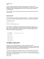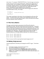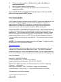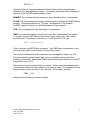
1
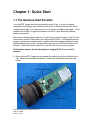
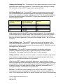
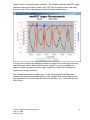
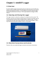
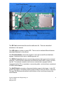
Precision Measurement Engineering, Inc. • www.pme.com
miniDOT Logger User’s Manual
2011
Precision Measurement Engineering, Inc.
(760) 727-0300
www.pme.com
1
(INTENTIONALLY BLANK)
Precision Measurement Engineering, Inc.
(760) 727-0300
www.pme.com
2
Warranty
1-YEAR LIMITED WARRANTY ON miniDOT HARDWARE
Precision Measurement Engineering, Inc. (PME) warrant that the miniDOT Logger
shall be free of defects in workmanship and materials, under normal use, for a period
of one year from the date of shipment. This warranty is made only to the original
purchaser. In the event a miniDOT Logger covered by this warranty fails to operate
according to our published specifications, then return it freight pre-paid to PME or an
authorized Service Provider. PME will repair the unit at no charge to the customer
and bear the cost of return shipment. Carefully pack all components, as the customer
is responsible for any freight damage.
This warranty does not apply to services or consumable / expendable items (such as
batteries, fuses and ropes) required for general maintenance. Equipment
manufactured by other companies (such as meteorology sensors, solar panels, etc)
are warranted only to the limit of the warranties provided by their original
manufacturer.
PME makes no warranty, either expressed or implied, that the sensors will be
operable after they are exposed to adverse environmental conditions, such as biofouling, oil fouling, freezing temperatures or others.
This warranty is void if, in our opinion, the miniDOT Logger has been damaged by
accident, mishandled, altered, or repaired by the customer, where such treatment has
affected its performance or reliability. In the event of such treatment by the customer,
costs for repairs plus two-way freight costs (no COD shipments will be accepted) will
be borne by the customer. In such cases, an estimate will be submitted for approval
before repair work is started. Items found to be defective should be returned to PME
carefully packed, as the customer will be responsible for freight damage.
Incidental or consequential damages or costs incurred as a result of the product
malfunction are not the responsibility of PME.
For all warranty or non-warranty returns please obtain, complete, and submit a RMA
to PME. This RMA form may be obtained at
http://www.pme.com/HTML%20Docs/RMAform.html.
After submission of this form, then PME will respond with a RMA number. Please
place this number on all shipments and related communications.
Precision Measurement Engineering, Inc.
(760) 727-0300
www.pme.com
3
Safety Information
BURSTING HAZARD
Should water enter the miniDOT Logger and come into contact with the enclosed
batteries, then the batteries may generate gas causing the internal pressure to
increase. This gas will likely exit via the same location where the water entered, but
not necessarily. The miniDOT Logger is designed to release internal pressure as the
end cap is unscrewed, prior to the disengagement of the end cap threads. If internal
pressure is suspected, then treat the miniDOT Logger with extreme caution.
Revision History
Date
20-JUL-2010
02-FEB-2011
14-MAY-2011
06-JUN-2011
08-JUN-2011
14-JUN-2011
16-JUN-2011
Revision Description
Initial document
Revised to show better Dataturbine screen, added Vega, misc changes
Extensively modified due to simplification of logger software
Modified to describe startup with no 3 flashes if no CAL.TXT file found. This to
be consistent with logger software change
Added o-ring and SD card information, multiple plot info
Minor wording changes; coin cell discharge description changed
Added no backspace instructions to command description
Precision Measurement Engineering, Inc.
(760) 727-0300
www.pme.com
4
CONTENTS
Chapter 1 Quick Start
1.1 The Quickest Start Possible
1.2 A Few Details
Chapter 2 Software
Chapter 3 miniDOT Logger
3.1
3.2
3.3
3.4
3.5
3.6
3.7
3.8
3.9
Overview
Opening and Closing the Logger
Electrical Connections and Controls
Connection to Serial Port
Output After Switching Power On
Mission Operation
File Close Button
Battery Replacement
Commands
Appendix 1 Serial Communication
Appendix 2 Re-Flashing
Precision Measurement Engineering, Inc.
(760) 727-0300
www.pme.com
5
Chapter 1: Quick Start
1.1 The Quickest Start Possible
Your miniDOT Logger has arrived completely ready to go. It is set to measure
temperature and oxygen concentration once every 10 minutes and record 4 files of
measurements daily. You need only turn on the power and deploy the logger. In this
condition the miniDOT Logger will operate for most of a year before the internal
battery is expended.
At the end of the deployment period you need only to open the logger, press the File
Close button, switch off the power, and remove the SD card. Your temperature and
oxygen concentration measurements, together with a time stamp indicating the time
the measurement was made, are recorded in text files in the DATA directory on the
SD card. These files can be copied from the SD card onto any host computer.
Follow these steps to start the deployment, logging DO & T once each 10
minutes:
1) Open the miniDOT Logger by unscrewing the white housing from the black end
cap. Remove the housing completely. Inside you will see the circuit pictured
below:
Precision Measurement Engineering, Inc.
(760) 727-0300
www.pme.com
6
2) Slide the power switch to the ON position. The LED will flash once. Observe the
LED for up to 90 seconds. Sometime during this period it will flash 5 times
indicating that logging has begun. If it flashes continuously, then see section 3.5
of this manual.
3) Inspect the o-ring seal for debris.
4) Close the miniDOT Logger by screwing the white housing back onto the black end
cap.
5) Deploy the miniDOT Logger.
Follow these steps to end the deployment
1) Recover the miniDOT Logger
2) Clean and dry all accessible surfaces except the ‘foil’.
3) Open the miniDOT Logger by unscrewing the white housing from the black end
cap. Remove the housing completely, taking care that water does not drip onto
interior surfaces of circuits or other items inside the logger.
4) Press the File Close button. The LED should begin continuous flashing.
5) Slide the power switch to the OFF position.
6) Remove the SD card. Use a card reader and a host computer to copy the files
located in the DATA directory onto the host computer. These text files contain the
measurements.
7) (Optionally) Run PME’s miniDOTPLOT.jar program to see a plot of dissolved
oxygen, temperature and oxygen saturation, and to produce a concatenated file
containing all the measurements.
Remove the battery if storing the miniDOT Logger for extended periods.
1.2 A Few Details
The previous section gives instructions for sampling at 10-minute intervals. However
there are a few additional details that will enhance use of the miniDOT Logger.
Sampling rate – The miniDOT Logger measures and records dissolved oxygen
concentration and temperature at equal time intervals. The default time interval is 10
minutes. If a formatted SD card is placed in the miniDOT Logger and the power is
turned on, then the logger will record every 10 minutes. However, it is also possible
to instruct the miniDOT Logger to record at different intervals. This is accomplished
by placing a specially named file in the root directory of the SD card. When power is
switched on, the software searches the SD card root directory and reads the sample
interval from the file, if found. Here are the rules for the file:
The file MUST be named CAL.TXT
The file MUST appear in the root directory of the SD card
Precision Measurement Engineering, Inc.
(760) 727-0300
www.pme.com
7
The file MUST contain either comments preceded by a “;” or a single statement of
sample interval in the format
SAMPLEINTERVAL x
where x gives the time between samples in minutes. Here is an example file that
causes the miniDOT Logger to make a measurement of dissolved oxygen and
temperature every 10 minutes.
;=======================================
; miniDOTLogger Calibration File
; CAL.TXT
; CREATED 24-AUG-2010
;=======================================
; SAMPLEINTERVAL: time between samples
;
(minutes)
;
;--------------------------------------SAMPLEINTERVAL 10
;
;
;=======================================
;
End of Cal file
;=======================================
Sample intervals of less than 1 minute or longer than 1 hour are not allowed and will
be rejected by the miniDOT Logger software. The miniDOT Logger will flash its LED
repeatedly if it encounters a sample interval request outside this range.
Sample Time – The miniDOT Logger records the time that each measurement of
dissolved oxygen and temperature is made. It does this based on an internal clock.
When your miniDOT Logger arrives it is set by PME to UTC (formerly known as
Greenwich mean time (GMT)). We suggest that you leave it always set to UTC so
that there is never a time question in the recorded measurements. Subsequent PME
software implements conversion to local time. You can reset miniDOT Logger time to
local time if you choose.
The miniDOT Logger internal clock will drift in the <10 ppm range (< about 30
seconds/month) so you should plan to reset it occasionally.
Please refer to Chapter 3 for instructions on setting time.
File Information – The miniDOT Logger software creates 4 files daily. The number
of measurements in each file will depend upon the sample interval. Files are named
by the time (Unix epoch 1970) that the file is opened based on the logger’s internal
clock and expressed in hexadecimal format.
Precision Measurement Engineering, Inc.
(760) 727-0300
www.pme.com
8
Cleaning the Sensing Foil – The sensing foil may require cleaning from time to time
depending upon deployment conditions. Clean these by gently wiping or brushing.
The delrin case of the miniDOT Logger can be gently scrubbed.
AA Lithium Battery Life – The miniDOT Logger consumes battery power mostly
from the measurement of dissolved oxygen, but also slightly from simply keeping
track of time, writing files, sleeping, and other activities. The following table presents
the approximate endurance of the miniDOT Logger when powered by the lithium
battery supplied by PME:
SAMPLE INTERVAL
(minutes)
1
5
10
15
60
Main AA Battery Life
(days of sampling)
200 days
400 days
475 days
500 days
530 days
Samples
288K
115K
68K
48K
12K
Keep a general record of miniDOT Logger number of samples. It is not possible to
tell the charge state of a lithium battery from measurements of its terminal voltage. If
you have a general idea of the number of samples already obtained on a battery,
then you can make a guess as to how many more samples remain. Err on the side
of caution.
Coin Cell Battery Life – The miniDOT Logger uses a coin cell for backup of the
clock when the power is switched off. This coin cell will supply roughly 2 years of
clock operation, but this is only required if the main power is off. Should the coin cell
discharge it must be replaced.
Recalibration – The miniDOT Logger will maintain its calibration without the
necessity of adjustment by the user. Loggers should be returned to PME for
recalibration. We suggest that this be done every ½ million samples.
O-Ring and Seal – When the cover is screwed on, it passes along the o-ring located
in the end cap several revolutions. Keep this o-ring lightly lubricated with silicone
grease or oil compatible with buna-N o-ring material.
When the miniDOT Logger is opened after deployment, a small number of water
drops are deposited on the inner surface of the o-ring. When the pressure housing is
screwed back on these drops become trapped inside the miniDOT Logger. Be sure
to carefully dry the o-ring and adjacent surfaces (especially underneath) prior to
closing the miniDOT. Re-lube the o-ring at this time.
SD Card – The SD card can be ejected from its socket if the miniDOT Logger is
dropped on its pressure housing end. The logger will be unable to log should this
occur. PME recommends that the SD card be secured in its socket in the normal way
Precision Measurement Engineering, Inc.
(760) 727-0300
www.pme.com
9
and then a small length of electrical tape added to hold the SD card in the proper
place.
Precision Measurement Engineering, Inc.
(760) 727-0300
www.pme.com
10
Chapter 2: Software
The miniDOT Accessory Kit includes software to concatenate and display miniDOT
Logger data files. This is a Java program, miniDOTPlot.jar. The Java Run Time
Engine (JRE) 1.6 or later is required. The JRE is commonly used and likely to
already be installed on your computer. If not, then download the current JRE from:
http://www.oracle.com/technetwork/java/javase/downloads/index.html
When miniDOTPlot runs it presents the screen shown below.
Your miniDOT Logger is supplied with time set to UTC. If you have not changed this
time definition, then enter the time zone of your locale in the Time Zone Offset box.
The software will read the miniDOT Logger time and compute local time based on
this time zone. If you have set the miniDOT Logger time to local time, then leave the
default of 0. PME recommends you always set the miniDOT Logger to UTC time.
The software will also compute oxygen saturation from the miniDOT Logger
measurements. To do this it must know the air pressure and salinity. It calculates air
pressure based on elevation of the water surface above sea level. No compensation
for weather-induced barometric pressure variation is made. Enter elevation. Enter
water salinity.
Select the import folder. This is the folder that contains your miniDOT Logger
measurement files. This folder MUST NOT contain any other files.
Select the export folder. This folder can be the same as the import folder or it can be
different. The software will write a CAT.TXT file into this folder. CAT.TXT is a
concatenation of all the miniDOT Logger files found in the import folder. CAT.TXT
includes the original data and in addition shows saturation value and local time.
Precision Measurement Engineering, Inc.
(760) 727-0300
www.pme.com
11
Press ‘Process’ to begin program operation. The software reads all miniDOT Logger
data files in the import folder, writes a CAL.TXT file in the export folder, and finally
presents a plot of the measurements similar to the plot shown below.
You may zoom this plot by drawing a square from upper left to lower right (click and
hold left mouse button) that defines the zoom region. To zoom completely out,
attempt to draw a square from lower right to upper left. Right click on the plot for
options such as copy and print.
The software may be run multiple times. In this case it produces multiple plots.
Presently the plots are presented exactly on top of each other and so when a new
plot appears it is not obvious that the old plot is still there. It is. Just move the new
plot to see it.
Precision Measurement Engineering, Inc.
(760) 727-0300
www.pme.com
12
Chapter 3: miniDOT Logger
3.1 Overview
All of the miniDOT Logger measurements pass from the sensors onto the SD card it
contains. Measurements may flow from the logger to host computer by removing the
SD card and copying the contents. Customers will be required to open the logger
each time measurements are obtained. This chapter describes the logger internal
features.
3.2 Opening and Closing the Logger
The logger circuitry is contained in a waterproof housing that must be opened. The
housing is opened by unscrewing the white pressure housing from the black end cap.
Turn the pressure housing counter clockwise relative to black end cap. Close by
reversing this procedure after being sure that the o-ring is free from debris. Lube oring occasionally with grease intended for buna-n o-ring material.
3.3 Electrical Connections and Controls
Removal of the cover reveals the logger connections and controls, shown below.
Precision Measurement Engineering, Inc.
(760) 727-0300
www.pme.com
13
The SD Card contains data files and the calibration file. These are described
elsewhere in this manual.
The LED Light is a yellow or green LED. This is used to indicate different features
described elsewhere in this manual.
The File Close Button causes the program to save the current file and halt data
logging. Press this button prior to switching power off.
The RS232 Connection allows communication between the logger and an external
computer. Communication parameters are 9600 baud with 8 bits, no parity, and one
stop bit. The external computer must have a communication program such as
Hyperterminal (for PC) or equivalent, a connecting cable, and must have a serial port
or USB to serial adapter.
The On/Off Switch connects or disconnects battery power to the logger. In the ‘Off’
position the logger is completely without power except for the clock circuit. Note that
‘On’ and ‘Off’ positions are marked in white letters on the circuit board nearby the
On/Off Switch.
Precision Measurement Engineering, Inc.
(760) 727-0300
www.pme.com
14
The Main Battery provides main power to the miniDOT Logger. Note the positive (+)
terminal. (See picture in Section 3.8).
The Command Jumper, if jumped, instructs the miniDOT Logger to enter its
command mode after the power is turned on. For normal operation leave the jumper
block on just one pin, not both.
3.4 Connection to Serial Port
The miniDOT Logger must be connected to a host computer to set its internal clock.
In addition, the miniDOT Logger produces statements as it tests itself after the power
is switched on. These statements can be used to diagnose any problems that occur.
PME supplies a connection cable in the miniDOT Accessory Kit that can be
purchased in addition to the miniDOT Logger. One cable will service many miniDOT
Loggers.
Connect the miniDOT Logger to a host computer by plugging the connection cable
into the RS232 connection within the miniDOT Logger. Connect the opposite end (9pin D connector) to the host computer’s serial port. On a PC desktop this is the COM
port. Some computers may not implement a COM port in which case the serial port
must be emulated by using a USB to Serial converter. PME supplies a serial-to-USB
converter in the miniDOT Accessory Kit.
In addition to the physical connection, the host computer must run a terminal
program. Windows 2000 and XP ship with Hyperterminal located at
programs|accessories|communication. The miniDOT Logger communicates as
shown in the table below. Appendix 1 shows how to set Hyperterminal for this
protocol and gives other information about communications programs.
Feature
Baud Rate
Bits sent per
byte
Parity
Stop bits sent
Flow control
Parameter
9600 (bits/second)
8 (bits)
none
1 (bit)
none
3.5 Output After Switching Power On
This section describes the LED indications and RS232 output produced by the logger
as it performs initialization activities and data logging after the power is turned on.
Note that the logger does not require any external computer connected for normal
start up. If a computer is connected, then the following output will be observed.
Precision Measurement Engineering, Inc.
(760) 727-0300
www.pme.com
15
The logger will indicate the results of various tests by using the LED lights and also
by printing statements via the RS232 connection. These results can be viewed if an
external computer is connected. The following paragraphs describe both the LED
operation and also the RS232 output.
Power is applied to the logger by setting the On/Off Switch to the ‘On’ position.
BANNER
After a brief delay the logger prints a banner similar to
===================
DOT Logger Rev 1.01
===================
Tue Oct 26 22:45:49 2010
This indicates that the end of basic system initialization has been reached. At this
time the miniDOT Logger flashes its LED Light once.
SD CARD
Next the SD card is initialized. If the initialization is successful, then the logger
prints:
SD OK!
SD: 1977614336 bytes
SD Disk OK!
PME ships a 2 GB SD card with the logger. If a different size card is used, then the
information displayed will be different. If the test fails, then the logger prints a
description of the problem and flashes the LED twice. The initialization is then re-run.
If the test fails once, then it will almost certainly fail again and the print will re-occur
with the LED flashing twice. Failure of this test can indicate major problems within
the logger. However the test will also fail if the SD card is not correctly plugged into
its socket. If this is suspected, then turn the power off, wait 15 seconds, then unplug
and re-plug the card. Try the start up again. This test must succeed for normal
operation. If it does not, then contact PME.
CALIBRATION FILE LOAD AND PARSE
Next, the calibration file loaded on the SD card is read and parsed. If the miniDOT
Logger finds a CAL.TXT file, but is unable to read or unable to parse this calibration
file, then the LED yellow light will flash 3 times and the read/parse will be attempted
again. In general, if this operation fails once, it will fail forever and the LED yellow
light will flash 3 times in a repeating pattern. If the read/parse is successful, then
there is no light indication and the LED yellow light remains off. The logger prints the
calibration file as it reads it and gives a statement for each line. This will generally
Precision Measurement Engineering, Inc.
(760) 727-0300
www.pme.com
16
look like: (note that the display may be different depending upon the information
actually recorded in the CAL.TXT file)
Parsing Cal File...
Seeking Calibration File: CAL.TXT
Parsing Cal File: CAL.TXT
Parsed OK!
;==================================
Parsed OK!
;
DOTLogger Calibration File
Parsed OK!
;
CAL00000.TXT
Parsed OK!
;
CREATED 24-AUG-2010
Parsed OK!
;==================================
Parsed OK!
;
Parsed OK!
; SAMPLEINTERVAL: time betweensamples
Parsed OK!
;
(minutes)
Parsed OK!
;---------------------------------Parsed OK!
SAMPLEINTERVAL
10
Parsed OK!
;
Parsed OK!
;
Parsed OK!
;==================================
Parsed OK!
;
End of Cal file
Parsed OK!
;==================================
Parsed CAL.TXT OK!
and the print will continue for all the statements in the file. Files will normally be
created by PME and tested. This read/parse should not fail. If it does, then contact
PME. This test must succeed for normal operation.
Note that no calibration file need be present on the SD card. In this case the above
display will not occur. The sample interval will be set to 10 minutes as the default
value.
PARAMETER VALIDATION
After parsing, the requested values are compared to internal limits of the logger
software. The logger prints check results shown below:
Checking Cal File...
OK! Scan interval: 600 (second)
OK! Scan/file: 144
If these checks fail, then the logger will print a description of the problem, flash the
LED light 3 times, and re-run the check. The check will most likely fail again resulting
in a flashing pattern of the LED. This check must succeed for normal operation. If
not, then contact PME.
CLOCK EVALUATION
The logger now evaluates the clock. Software cannot tell that the time is correct, but
it can tell if the clock is not initialized.
Precision Measurement Engineering, Inc.
(760) 727-0300
www.pme.com
17
Checking clock...
OK!
If the clock check fails, then the miniDOT Logger will print a description of the
problem, flash the LED light 4 times and re-run the check. The check will most likely
fail again resulting in a flashing pattern of the LED. This check must succeed for
normal operation.
If this test fails, then turn the power off and set the clock as described in Section 2.9
of this manual.
MISSION START
The miniDOT logger continues by starting the mission. The mission of the logger is
to measure and record dissolved oxygen and temperature at equal time intervals.
The logger now prints:
Mission Starting...
Syncronizing to Minute...56
Tue Oct 26 22:46:00 2010
During this time the logger waits until the next minute boundary is read from the
clock. There is no LED output. When the next minute occurs the logger flashes the
LED 5 times to indicate that the mission has started. Thereafter the logger prints
statements indicating its logging activities.
(2) Scan: 0
(2) Opened:
(5) Scan: 1
(10) Scan: 2
(15) Scan: 3
(20) Scan: 4
(25) Scan: 5
(30) Scan: 6
(35) Scan: 7
(40) Scan: 8
0:/RAW/4CC75A2A.raw
3.6 Mission Operation
The mission of the miniDOT logger is to acquire, at fixed time intervals,
measurements from the dissolved oxygen and temperature sensors, to acquire a time
stamp for each measurement, to compute calibrated values in engineering units from
these data, and to write these data in files on the SD card.
Throughout the deployment the logger is mostly in a very low power mode, a ‘sleep’
mode, and is ‘awakened’ by the system clock. This clock can wake the logger from
sleep either at 1-minute intervals, or 1-hour intervals. It cannot awaken the logger at
Precision Measurement Engineering, Inc.
(760) 727-0300
www.pme.com
18
other interval. For example, if SAMPLEINTERVAL is 5 then the logger must awaken
5 times (once per minute) for each measurement. Awakening the logger does not
cost much energy, but is something to consider when selecting a sample interval.
For example, a sample interval of 1 hour will awaken the logger only once per hour
for an hourly measurement, but a sample interval of 59, while nearly the same
interval, will awaken the logger 59 times for each measurement.
If a computer is connected to the RS232 Output, then the logger prints statements
that describe what it is doing. An example:
(2)
(2)
(5)
(10)
Scan: 0
Opened:
Scan: 1
Scan: 2
0:/RAW/4CC75A2A.raw
The number in parenthesis is the number of seconds elapsed since the start of the
mission. The scan number is the number of scans obtained since the start of the
mission. From time to time the logger will open or close a SD card file and indicates
this with a statement similar to that above.
3.7 File Close Button
The logger records individual measurements to the SD card file when the
measurement is made. After each measurement the file remains open. If the power
fails or is switched off while the file is open, then the file information is lost. Files are
recorded 4 times daily so only as much as 6 hours of measurements are at risk. The
user must inform the miniDOT software that the power is about to be switched off by
pressing the File Close button. The software will detect this action and close the
presently open file. Thereafter the logger will halt its mission, flash its LED
repeatedly and print the following statement repeatedly over the serial connection.
Mission
Mission
Mission
Mission
Halted!
Halted!
Halted!
Halted!
TURN
TURN
TURN
TURN
POWER
POWER
POWER
POWER
OFF!
OFF!
OFF!
OFF!
There is no way to exit this loop except by turning the logger power off.
3.8 Battery Replacement
Improper replacement of the battery will damage the miniDOT Logger. Follow these
steps:
1)
2)
3)
4)
If the logger is logging, press the File Close button.
Move the On/Off Switch to the Off position.
Remove the depleted battery noting the position of the (+) terminal.
Install the fresh battery with the (+) position the same as the removed
battery. The (+) position is also marked on the chassis nearby the proper end
of the battery holder.
Precision Measurement Engineering, Inc.
(760) 727-0300
www.pme.com
19
5)
6)
7)
Review the battery installation. Be sure the (+) end of the battery is
properly positioned!!
Move the power switch to the On position.
The miniDOT Logger LED Light should flash once to indicate that it is
beginning operation.
If you install the battery backwards and turn the power on, then you should
plan to purchase a new miniDOT Logger.
3.9 Commands
If the Command Jumper is jumped and the miniDOT Logger power switched on, then
the mini DOT Logger will enter its command mode and become responsive to
commands sent over the RS232 connection. In general these commands are
implemented to aid PME with troubleshooting the logger circuit and should not
concern customers, with one important exception, which is setting time.
General information: Commands are all uppercase words. If the command word only
is typed, then commands that accept parameters will respond with the required
parameter list. If the command word followed by a trailing space character is typed,
then the command will respond with the value of the parameters. Parameters are
integers separated by commas. miniDOT can not interpert backspace characters.
You can not back up and correct a miss-typed line. The entire line must be entered
correctly.
ADJUST This command allows adjustment of the clock speed. To adjust the clock,
set the clock to UTC time using the Internet.
http://www.time.gov/
Wait several days, observe the logger time and at the same time observe the true
Internet time. Compute the clock speed error in ppm. The ADJUST command
accepts one parameter, which is the adjustment integer. Positive integers speed up
the clock by 4.086 ppm, negative integers slow the clock down by 2.034 ppm per unit.
Here is an example:
Clock set: 11-AUG-2010 20:00:00
True time at observation: 15-AUG-2010 20:00:00
Logger indicated time at observation: 15-AUG-2010 20:00:05
Elapsed time: 345600 (seconds) (the 4 elapsed days from setting to observing)
Time error: +5 (seconds)
error in ppm: (5/345600) * 1E6 = 14.46 (ppm) (logger clock has run fast)
correction integer: 14.46/(-2.034) = -7 (slows fast clock down by 14.23 ppm)
This parameter is set by the command
Precision Measurement Engineering, Inc.
(760) 727-0300
www.pme.com
20
ADJUST –7
Note that if there is already an adjustment then its effect must be included when
determining the new adjustment integer. The existing adjustment will be displayed in
response to an ADJUST<space character> entry.
BANNER This command shows current time and software revision; no parameters.
FLASH This command exits the logger operating system and enters a ROM flashing
program. This program displays a ‘?’ prompt. See Appendix 2, Re-Flashing
miniDOT Logger for further use. Exit this program by cycling power.
TICK This command prints time repeatedly; no parameters.
TIME This command displays current time or sets time if parameters are supplied.
To set the time type TIME followed by the time in year, month, day, hour, minute,
second format. For example to set time to 11-AUG-2010 21:02:14 type
TIME
2010,8,11,21,2,14
Time is set when the ENTER key is pressed. Type TIME with no parameters to see
the current time and to insure that the time you set is correct.
The clock will accept any time but customers are encouraged to always use UTC.
This eliminates any question about time zone, and daylight savings time when
reviewing historic data. Subsequent PME software will compute local time if miniDOT
Logger time is set to UTC.
The command may be entered with just commas. If this is done the parameter prior
to the comma receives the value shown in the previous output. For example the time
response above can be modified to be 3 minutes, 15 seconds by entering
TIME ,,,,3,15
Always check time after you make a change!
Precision Measurement Engineering, Inc.
(760) 727-0300
www.pme.com
21
APPENDIX: 1 – Serial Communication
When the power to the miniDOT Logger is turned on the logger performs various
tests and produces a serial output. This output is always produced. A terminal does
not need to be connected in order for the miniDOT Logger to begin normal operation.
There is an indicator LED that can be viewed to see if the logger has begun normal
operation (it will flash 5 times after testing itself and just prior to beginning logging). It
is, however, very re-assuring to see the test result statements and these statements
are necessary to troubleshoot the logger should some test fail. Tests and
statements are described in Chapter 3 of this manual.
A terminal emulator program such as Hyperterminal should be installed on the PC lap
top computer that is used to service the miniDOT Logger. Hyperterminal ships with
Windows 2000 and Windows XP, but has disappeared from later Windows operating
systems. Mac laptops can also be used if they have the proper software and RS232
port.
On Windows 2000 and XP Hyperterminal may be found under
start\Accessories\Communications\Hyperterminal.
In addition to a communications program, the laptop must have serial COM port.
Most modern laptops lack this port. A USB to serial adapter is supplied by PME in
the miniDOT Accessories Kit or can be purchased for a small cost. In general the
adapters must be physically plugged into the computer USB port and the software
properly installed prior to using Hyperterminal or another communications program.
Follow the manufacturer’s installation instructions.
The miniDOT Logger communicates via an RS232 (+/- 5 V protocol) at 9600 Baud, 8
bits, no parity, 1 stop bit.
Hyperterminal Setup
Hyperterminal must be set up for miniDOT Logger communication. Run
Hyperterminal, select File\New Connection. A Connection Description dialog box will
appear.
In the Connection Description dialog window enter miniDOT in the Name box, then
press OK.
Precision Measurement Engineering, Inc.
(760) 727-0300
www.pme.com
22
A “Connect To” dialog window will appear. Select the correct COM number for the
laptop (usually COM 1) or the USB adapter (could be COM 3 or COM 4 or other) from
the “Connect using” drop down box. Press OK. A “Port Settings” dialog box will
appear.
In the “Port Settings” dialog box select 19200 in the “Bits per second” drop down box,
8 in the “Data bits” drop down box, None in the “Parity” drop down box, 1 in the “Stop
bits” drop down box and None in the “Flow control” drop down box. Press OK.
Precision Measurement Engineering, Inc.
(760) 727-0300
www.pme.com
23
Select File \Save. This will save your connection so that it can be reloaded at a
future time.
The installation can be tested by connecting the laptop to the miniDOT Logger and
turning the power on briefly. The connection is working if the miniDOT Logger prints
its banner and begins making test statements.
PuTTY Setup
Another free terminal program can be downloaded from
http://www.chiark.greenend.org.uk/~sgtatham/putty/download.html
Run the putty.exe. Select ‘serial’ in the left hand tree, set the serial parameters as
shown below. Select ‘Session’ in the left hand tree, select ‘Serial’ as shown below.
Press the ‘Open’ button to begin the session.
Precision Measurement Engineering, Inc.
(760) 727-0300
www.pme.com
24
Precision Measurement Engineering, Inc.
(760) 727-0300
www.pme.com
25
APPENDIX: 2 – Re-Flashing
In general, customers will never re-flash a miniDOT Logger. These instructions are
place here in case some unforeseen software revision is required.
1. Set miniDOT to accept commands as described in Section 3.9. Give the FLASH
command. miniDOT should respond with a ?
2. Select Hyperterminal File -> Properties-> Settings -> ASCII Setup, change Line
Delay to 50 milliseconds. Make sure ‘Send line ends with line feed’ is
checked.
3. Type C to get a checksum value. Note the value because it will be proof that we
have changed the miniDOT Logger’s memory.
4. Type E 1100 FBFF. This is the erase command. You’ll be erasing the memory
that the miniDOT program is located in. Erasing will take a couple seconds. A little
display will show progress on screen. Don’t turn the power from this point until
the new software is installed!!
5. Type C again. C880 should appear. This will prove that the memory is in fact
cleaned out.
6. Type U. Then click in hyper terminal’s command bar. Transfer -> Send Text File .
Select the file supplied by PME that contains the new software. This will
immediately start the re-programming process. Be sure to let it run completely to
its finish. You’ll know when it’s finished when the ? comes back. Reprogramming
may take 2-3 minutes. Output on hyperterminal will halt when done. There is no
‘done’ statement.
7. Cycle the power to begin the miniDOT Logger operation. If the command jumper
is jumped, then the miniDOT Logger will enter command mode. Otherwise it will
begin normal logging operation.
Precision Measurement Engineering, Inc.
(760) 727-0300
www.pme.com
26