1
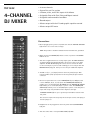
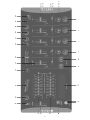
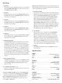
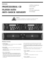
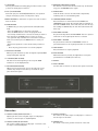
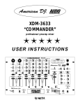
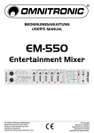
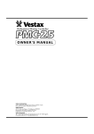
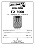
Ref. No. 170.408
19" DUAL CD PLAYER, MIXER AND CASE
USER MANUAL
1
CAUTION
RISK OF ELECTRIC SHOCK DO NOT OPEN
To prevent electric shock, do not remove top or bottom covers. No user serviceable parts inside.
Refer servicing to qualified servicing personnel. Disconnect power cord before removing back panel cover to
access gain switch.
WARNING
To reduce the risk of electric shock, do not expose this equipment to rain or moisture!
WATCH FOR THESE SYMBOLS
The exclamation point triangle is used to alert the user to important operating or maintenance instructions.
The lighting bolt triangle is used to alert the user to the risk of electric shock.
2
TEC1242
• 4 stereo channels
4-CHANNEL
DJ MIXER
• 3 Phono, 8 Line, and 5 Mic inputs with talkover
• State of the art Cue section
• Assignable Echo with Gain, Delay and Repeat control
• Assignable and removable crossfader
• Record output
• Master output with dual 7 bands graphic equalizer control
• Master output LED meter
Connections
1. Before plugging in the power cord, make sure that the VOLTAGE SELECTOR
(59) switch is set to the correct voltage.
NOTE: This product is double insulated and not intended to be grounded.
2. Make sure that the POWER (40) switch is in the off position. The POWER
LED will be off.
3. This unit is supplied with 4 sets of amp output jacks. The MAIN OUTPUTS
are balanced (57) and unbalanced (56) to be used to connect your main
amplifier. The REC OUTPUT (54) jacks can be used to connect the mixer
to the record input of your recorder enabling you to record your mix. The
BOOTH OUTPUT (55) jacks allow you to hook up an additional amplifier.
4. The MIC 1-4 (1, 2, 3, 4) input (found on the front panel) accepts XLR
Connector. MIC 5 (42) input (found on the rear panel) accepts 6.35mm
connector.
5. On the rear panel there are 3 stereo PHONO/LINE (44, 47, 50)inputs and
5 stereo LINE (45, 48 ,51, 52, 53) inputs. The PHONO/LINE SWITCH (43)
enables you to set the (44) input TO PHONO line. The PHONO/LINE SWITCH
(46) enables you to set the (47) input to phono or line. The PHONO/LINE
SWITCH (49) enables you to set the (50) input to phono or line. The phono
inputs will accept only turntables with a magnetic cartridge.
A GROUND SCREW (58) for you to ground your turntables located on the
rear panel.
The stereo line inputs will accept any line level input such as a CD player, a
cassette player, etc.
6. Headphones can be plugged into the front panel mounted HEADPHONE
(38) jack.
7. This unit comes with a front panel BNC LIGHT (39) JACK.
3
5, 6, 7, 8
11, 14,
16, 18
13, 15,
17, 19
26
1
27
29
2
30
31
3
22
4
24
10
21
9
23
32
35
36
39
38
40
34
37
33
4
Operation
NOTE: The REC OUTPUT (52) has no level control. The Level is set
by the channel slides or the selected channel. The tonal qualites
can be controlled by the equalizers.
1. POWER ON
Once you have all the equipment connections to your mixer,
press the POWER SWITCH (40). The power will turn on and
the POWER LED will glow RED.
10. TALKOVER SECTION
The purpose of the talkover section is to allow the program
playing to be muted so that the mic can be heard above the
music. The MIC/TALKOVER SWITCH (26) controls MIC 1-4
and has three settings. When the MIC/TALKOVER SWITCH
(26) is in the bottom position, MIC 1-4 talkover are off.
When the MIC/TACKOVER SWITCH (26) is in the center
position MIC 1-4 are on, but talkover is off. When the
MIC/TALKOVER SWITCH (26) is in the top position, MIC 1-4
talkover will be on and the volume of all sources except the
Mic inputs are lowered by 16 dB. The TREBLE (9) and BASS
(10) controls allow you to fully adjust the tone of MIC 1-4.
The LEVEL (5-8) controls the level of MIC 1-4.
2. CHANNEL 1
Switch (11) allows you to select the PHONO1/LINE1 (44) or
the LINE2 (45) input. The CHANNEL SLIDE (13) controls the
input level of this channel.
3. CHANNEL 2
Switch (14) allows you to select the PHONO2/LINE3. (47) or
the LINE4 (48) input. The CHANNEL SLIDE (15) controls the
input level of this channel.
4. CHANNEL 3
Switch (16) allows you to select the PHONO3/LINE5. (50) or
the LINE6 (51) input. The CHANNEL SLIDE (17) controls the
input level of this channel.
11. CUE SECTION
By connecting a set of headphones to the HEADPHONE
(38) Jack, you can monitor any or all of the channels.
Press the CUE (12) buttons for channels 1-4 to select the
channel or channels to be monitored and their respective
LED indicators will glow. Use the CUE LEVEL (36) control to
adjust the cue volume without effecting the over all mixer.
By moving the CUE/PGM (35) control to the left you will be
able to monitor the assigned cue signal. Moving the control
to the right will monitor the PGM (program) output.
5. CHANNEL 4
Switch (18) allows you to select the LINE7, LINE 8 and MIC5.
(52, 53, 42) input. The CHANNEL SLIDE (19) controls the
input level of this channel.
6. CROSSFADER SECTION
The CROSSFADER (24) allows the mixing of one source into
another. This unit features an assignable crossfader. The
ASSIGN (22, 23) switches allow you to select which channel
will play through each side of the crossfader. The ASSIGN
(22) switch has 5 settings (OFF, 1, 2, 3 or 4) and allows you
to select channel1, 2, 3 or 4 to play through the left side of
the crossfader. The ASSIGN (23) switch has 5 settings (OFF,1,
2, 3 or 4) and allows you to select channel 1, 2, 3or 4 to play
through the right side of the crossfader. With the ASSIGN
switch in the off position, that side of the crossfader will be
inactive.
12. DISPLAY
The DISPLAY (32) indicates either the MASTER output left
and right levels.
Specifications:
INPUTS:
DJ Mic . . . . . . . . . . . . . . . . . . . . . . . . . . . . .1.5Mv 2Kohm balanced
Phono. . . . . . . . . . . . . . . . . . . . . . . . . . . . . . . . . . . . . . . . .3mV 47kΩ
Line. . . . . . . . . . . . . . . . . . . . . . . . . . . . . . . . . . . . . . . . 150MV 27kΩ
Aux . . . . . . . . . . . . . . . . . . . . . . . . . . . . . . . . . . . . . . . . 150MV 27kΩ
7. EFFECT CONTROL SECTION
The ECHO (27) button allows you to turn ON/OFF the effect
to master. The LEVEL (31) to allows you to adjust the effect
level. The REPEAT (30) and the DELAY (29) allow you to
adjust the effect.
OUTPUTS:
Main/Aux . . . . . . . . . . . . . . . . . . . . . . . . . . . . . . . . . . . 0dB 1V 400Ω
Max . . . . . . . . . . . . . . . . . . . . . . . . . . . . . . . . . .20dBV peak to peak
Rec . . . . . . . . . . . . . . . . . . . . . . . . . . . . . . . . . . . . . . . . . 225mV 5kΩ
8. The GRAPHIC EQUALIZER (33, 34)
Allows you to adjust the frequency response to achieve the
desired sound required.
MIC1-5:
DJ Mic . . . . . . . . . . . . . . . . . . . . . . . . . . . . . . . 1.5mV 2kΩ balanced
Bass . . . . . . . . . . . . . . . . . . . . . . . . . . . . . . . . . . . . . . . . . . . . . +12dB
High . . . . . . . . . . . . . . . . . . . . . . . . . . . . . . . . . . . . . . . . . . . . . +12dB
9. OUTPUT CONTROL SECTION: The level of the MAIN OUTPUT
(56, 57) is controlled by the MASTER (21) slide. The BOOTH
(37) control adjusts the level of the BOOTH OUTPUT (55).
GENERAL:
Frequency response . . . . . . . . . . . . . . . . . . . . . 20Hz-20KHz+/-2dB
Distortion. . . . . . . . . . . . . . . . . . . . . . . . . . . . . . . . . . . . . . . . . 0.02%
S/N Ratio . . . . . . . . . . . . . . . . . . . . . . . . . . . . . . . . better than 80dB
Taklover attention . . . . . . . . . . . . . . . . . . . . . . . . . . . . . . . . . -16dB
Headphone impedance . . . . . . . . . . . . . . . . . . . . . . . . . . . . . . . 16Ω
Power source . . . . . . . . . . . . . . . . . . . . 115V/230V 60Hz/50Hz 15W
HINT: The BOOTH OUTPUT (55) is used by some DJs to run
monitor speakers in their DJ Booth.You can also use it as a
second ZONE or AMP output.
5
TEC2420
PROFESSIONAL CD
PLAYER WITH
ANTI-SHOCK MEMORY
• 3 different speed scan
• Frame search
• Auto CUE
• 20 tracks program play
• Pitch display
WARNING!
Use of controls or adjustments or performance of procedures other than
those specified herein may result in hazardous radiation exposure.
CD player function
Jog: In pause mode, if you turn the Jog, the point at which
the sound is being produced moves by a number of frames
corresponding to the number of clicks. Dialing clockwise moves
the point forward, dialing counter-clockwise moves the point
backward.
1. POWER BUTTON
Press the POWER switch to turn the unit on. Press the POWER
switch again to turn the unit off.
2. EJECT BUTTON
Press this button to load or eject disk. Each press will open or
close the disk tray.
NOTE: Disk cannot be ejected unless STOP or PAUSE button
has been pressed first.
In play mode, the Jog increases or decreases the speed of the
song. (clockwise: increase, counter-clockwise: decrease)
4. SKIP |<< BUTTON
Use this switch to re-start the track or to select the previous
track.
3. JOG & SHUTTLE WHEELS
Shuttle: Use the dial to select the scanning direction and
speed. The disk is scanned in the forward direction when the
shuttle dial is turned clockwise from the neutral position, in
the reverse direction when the shuttle dial is turned counterclockwise. The scanning speeds up when the shuttle dial is
turned faster.
5. +10 BUTTON
Use this button to jump 10 tracks in one press.
6. SKIP >>| BUTTON
Used this knob to select the next track.
6
7. CUE BUTTON
Pressing the CUE button during play provides a return to the
position at which play was started.
14. RELOOP BUTTON (LOOP SYSTEM)
This button is used to start the last saved loop. To finish the
loop, press the RELOOP button again.
8. PLAY / PAUSE BUTTON
Each time you press the PLAY/PAUSE button, the operation
changes from play to pause or from pause to play.
15. TIME BUTTON
Used this knob to choose the time mode: elapsed time,
remaining time or total remaining time.
9 REPEAT BUTTON Use this button to repeat one track or all the
track of the CD.
16. CONTINUE/SINGLE BUTTON
Press this button to switch between the SINGLE and
CONTINUOUS play mode. The selected mode is indicated on
the LCD. In SINGLE mode, after each track, the unit will stop
the reading. In CONT model, the unit will read all track and
then stop.
10. PROG BUTTON
In STOP mode, you can program several tracks (20 tracks
max)
- Press the STOP button to enter the stop mode
- Press the PROG button to enter the program mode
- Use the skip track buttons to choose the track you want to
listen then press the PROG button to enter you choice.
- Use again the skip track buttons to choose the track you
want to listen then press the PROG button to enter you
choice.
- Repeat the operation to select all the track you want to
listen
- Press the play / pause button to start the playback.
17. PITCH BEND- BUTTON
The pitch will drop while the PITCH BEND- button is pressed
and return to the original pitch when it is released.
18. PITCH BEND + BUTTON
The pitch will rise when the PITCH BEND + button is
pressed and return to the original pitch when it is released.
19. STOP BUTTON
Press this button to stop the playback.
11. DIGITAL OUT BUTTON
When you push this button, there are digital outputs (CINCH
and optical digital outputs)
20. PITCH BUTTON
When this button is pressed, the adjustment of the pitch
potentiometer is available. (see item 22)
12. A BUTTON (LOOP SYSTEM)
This button sets the beginning of the loop. The LOOP
indicator is on the display flashes.
21. DISPLAY
22. PITCH CONTROL
Use this fader to increase or decrease the speed of the track.
13. B BUTTON (LOOP BUTTON)
When you press this button, you set the end point of the
seamless loop and you start the loop. To finish the loop,
press this button again.
Connection
23. DIGITAL OUTPUT (OPTICAL) PLAYER 1
Optical jack. This socket is digital output for CD player 1.
Connect to the line input of a D/A Amplifier.
25. LINE OUT PLAYER 1
This socket is the audio output for CD player 1. Connect to
the line input of the mixer.
24. DIGITAL OUTPUT (RCA) PLAYER 1
This socket is digital output for CD player 1. Connect to the
line input of the D/A Amplifier.
26. GROUND LIFT
The switch controls the ground connection of this unit.
7
27. POWER SUPPLY SWITCH
Use this selector to choose the correct corresponding
voltage of power supply.
31. LINE OUT PLAYER 2
This socket is the audio output for CD player 2. Connect to
the line input of the mixer.
28. AC POWER
Use power cable to connect this unit to the A/C main
power.
32. DIN SOCKET
Connect all the sockets using the mini-DIN cable provided
with the CD player. Connect the player 1 with the part 1
of the controller and the player 2 with the part 2 of the
controller.
29. DIGITAL OUTPUT (OPTICAL) PLAYER 2
Optical jack. This socket is digital output for CD players.
Connect to the line input of the D/A Amplifier.
30. DIGITAL OUTPUT (RCA) PLAYER 2
This socket is digital output for CD players. Connect to the
line input of the D/A Amplifier.
Specifications
Anti-Shock Buffer Memory . . . . . . . . . . . . . . . . . . . . . . 30 seconds
Audio response . . . . . . . . . . . . . . . . . . . . . . . . <2dB (20Hz-20kHz)
D/V converter . . . . . . . . . . . . . . . . . . . . . . . . . . . . . . . . . . . . 24 bits
Frequency response: . . . . . . . . . . . . . . . . . . . . . . . . . . .20Hz-20kHz
Harmonic distortion: . . . . . . . . . . . . . . . . . . . . . . . . . . . . . . .<0.1%
Signal / noise ration: . . . . . . . . . . . . . . . . . . . . . . . . . . . . . . . . 85dB
Dynamic: . . . . . . . . . . . . . . . . . . . . . . . . . . . . . . . . . . . . . . . . . . 80dB
Cross talk: . . . . . . . . . . . . . . . . . . . . . . . . . . . . . . . . . . . . . . . . . 60dB
Output level . . . . . . . . . . . . . . . . . . . . . . . . . . . . . . . . . . . . . . . .1.5V
Load impedance . . . . . . . . . . . . . . . . . . . . . . . . . . more than 47kΩ
Speed edge (PITH). . . . . . . . . . . . . . . . . . . . . . . . . . . . . . . . +/- 16%
Power supply . . . . . . . . . . . . . . . . . . . . . . . . . . . . . . . . 115/ 230 Vac
w w w. s k y t r o n i c . c o . u k
w w w. s k y t r o n i c . c o m
8