1
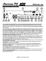
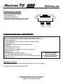
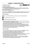
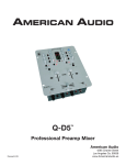
XDM-3633
“COMMANDER”
professional preamp mixer
USER INSTRUCTIONS
djs wanted.
XDM-3633
“COMMANDER”
The Ultimate DJ & Club Mixer!
Main Features
• 3 phono, 6 line, 3 auxiliaries & 3 mic inputs
• Balanced outputs • Rotary Kills
• High quality Feather Fader™ for smooth, clean crossfades
(replaceable/Made in Japan)
• Bass, mid, and treble for each channel
• 2 independent microphones with separate bass, mid, & treble with
Neutrik™ connection - 1/4” (6.3mm)/XLR
• 2 zones with bass and treble
• Zone 2 is assignable to any of the 4 channels
• Mono/Stereo switches on Master & Zones
• High level headphone output • Cue mixing • Split cue for headphones
• Low cut bass switch / -30dB cut feature for bass
• Auto mute • Talkover level control
• Send & receive for every channel including independent mics all selectable at the same time
• Left & right turntable ground connectors conveniently located
at each end of the rear panel
• Master level LED display w/ peak hold
• Pre Fader Levels (PFL) for each channel
• Accurate beat LED’s for easy crossfades • On/Off switch for channel assign
• LED display for each channel • Gain control for each channel
Independent light control output for touch panels and chase controllers 1/4” connection • Soft-touch rubber knobs for better control
• 12V DC BNC connector for gooseneck light • Rear inset “L” shape case design
• 110V/220V switchable • 2 year limited warranty
professional products designed for the working dj.
© American DJ® AUDIO Los Angeles, CA 90058 USA
Specifications subject to change without notice.
XDM-3633 User Instructions page 2
Index
•
•
•
•
•
•
•
•
Safety Instructions..................................................................................p.3
Operating Determinations.......................................................................p.4
Connections.............................................................................................p.4
Functions (Front Panel)........................................................................p.5-6
Inputs & Outputs (Rear Panel)...............................................................p.7
Replacing the Crossfader.......................................................................p.7
Technical Specifications.........................................................................p.7
Warranty & Service..................................................................................p.8
Thank you for purchasing this American DJ® product. The XDM-3633 Is ready to be
used, there Is no assembly required. Please read the following Instructions before
installing or using your new unit. The XDM-3633 has a 2 year limited warranty!
CAUTION! - Keep this device away from rain and moisture!
Safety Instructions
Always plug in the power last. Make sure that the Power switch is set to the OFF position before connecting other
devices to the mixer.
Keep away from heaters and other heating sources!
If the device has been exposed to drastic temperature fluctuation (e.g. after transportation), do not switch on the mixer
immediately. The arising condensation of water might damage your device. Leave the device switched off until it has
reached room temperature.
Never put any liquids on the mixer or close to it. Should any liquid enter the device, disconnect from main power
immediately. Have the device checked by a qualified service technician before operating again. Any damage caused
by liquid entering the device is not subject to warranty!
Never let the AC cord come in contact with other cables! Handle the AC cord and all AC connections with particular care.
Make sure that the available voltage is not higher than stated on the AC voltage selector (50).
Before the device is switched on, all fader and volume controls should be set to 0 (zero) or minimum position.
Damages caused by manual modifications to the device or unauthorized operation by unqualified persons are not
subject to warranty.
There are no user serviceable parts inside the mixer. For maintenance and/or service, contact an authorized American
DJ® dealer.
XDM-3633 User Instructions page 3
Operating Determinations
When installing this mixer, please make sure that the device is not exposed to extreme heat, moisture or dust! There
should not be any cables lying around. Doing so endangers you as well as others. Do not operate the mixer in extremely
hot (more than 30° / 100°F) or extremely cold (less than 5°C / 40°F) surroundings. Keep away from direct sunlight and
heaters.
Operate the mixer only after becoming familiar with its functions. Do not permit operation by persons not qualified for
operating the mixer. Most damages are the result of unprofessional operation!
Never use spray cleaners to clean the faders! Never use solvents or abrasive detergents to clean the mixer! It is recommended that you use a soft damp cloth. Please consider that unauthorized modifications on the device are forbidden
due to safety reasons!
Connections (Refer to diagrams on pages 5 & 6)
• Make sure that the POWER SWITCH (1) is set to OFF. Before connecting other devices to the mixer, all units have to
be switched off and the MASTER FADER (31) is set to min.
• Make sure that the available voltage is not higher than stated on the voltage selector (50) before connecting to power.
• In order to obtain the highest sound quality, only use high quality American DJ®, Ameri-Cable ™ cables for connecting
devices. Make sure that the cables are properly fixed.
• Connect your amplifier to the MASTER OUTPUT jacks (43) or BALANCED OUTPUT XLR jacks (47). Make sure that
(L & R) channels are set properly. For mono or bridged operation, you should use the the BALANCED OUTPUT XLR
jacks (47) and set the MASTER MONO/STEREO switch (32) to MONO.
• For recording, connect your tape recorder or cassette deck to the REC OUT jacks (44). The REC OUT level will not be
influenced by the MASTER FADER (31).
• The XDM-3633 features three microphone inputs. MIC 1 and MIC 2 Neutrik™ connector jacks (9) are on the front
panel for 1/4 inch (6.3mm) jack plugs or XLR-plugs. With the TALKOVER switch associated with MIC 1 (11), you can
attenuate all other signals without affecting the microphone volume. You can switch MIC 1 and MIC 2 (11) off by setting
the TALKOVER SWITCH to MICRO OFF. The 1/4 inch (6.3mm) MIC 3 jack (36) is on the rear panel. You can connect
your third microphone here. Adjust the microphone volume for MIC 3 by using the channel fader for CHANNEL 4. Make
sure that the LINE 5/LINE 6/ MIC 3 SWITCH is set to MIC 3. CAUTION: You can only cut the MIC 3 jack (36) off by setting the CHANNEL 4 fader to 0 or by switching the LINE5/LINE6/MIC 3 SWITCH to LINE 5 or LINE 6.
• You can connect 3 turntables using the PHONO 1/AUX 1 (37), PHONO 2/AUX 2 (38), and PHONO3/AUX 3 (39) jacks
on the rear panel. You can only control the turntables signal after you have switched the PHONO /AUX SELECTOR
SWITCH (41) on the rear panel to PHONO, plus you must change the PHONO/AUX/LINE SWITCH (3) on the front
panel to PHONO/AUX. The signal is then controlled via the CH-1, CH-2, OR CH-3 faders (17).
• Connect your tape player, tuner, sound effects, CD player, and cassette decks etc. to the LEFT & RIGHT RCA LINE
signals (37, 38, 39, 40 & 41) on the rear panel. The signal is then controlled via the CH-1, CH-2 AND CH-3 faders (17)
when the PHONO/AUX SWITCH on the front panel (3) is switched to LINE . CD players, cassette decks etc. may also
be connected to the LEFT & RIGHT RCA PHONO/AUX jacks (37, 38 & 39) on the rear of the unit. You can only control
this signal after you have switched the PHONO / AUX SELECTOR SWITCH (41) on the rear panel to AUX, plus you
must change the PHONO/AUX/LINE SWITCH (3) on the front panel to PHONO/AUX. The signal is then controlled via
the CH-1, CH-2, CH-3, and CH-4 faders (17).
XDM-3633 User Instructions page 4
Functions (Front Panel)
10
9
8
6
7
4
3
2
34
33
32
31
28
29
30
1
27
11
25
24
13
23
12
14
15
5
16
17
18
15
19
20
21
22
26
(1) POWER SWITCH - Red LED will light when power is ON.
(2) LOW / MID / HI CONTROL - Used to increase or decrease the LOWs (bass), MIDs and HIs (treble) of the input
signal for each channel. The XDM-3633 features “Rotary Kills” with -30dB to +20dB output control.
(3) PHONO / AUX / LINE SWITCH - Used to select the input to be sent to the individual channel. Channels 1 and 2 may
be switched PHONO/AUX or LINE, Channel 3 may be switched PHONO/AUX, LINE 3 or LINE 4, and Channel 4 may be
switched LINE 5, LINE 6 or MIC 3. The selectors for AUX1/PHONO1, AUX2/PHONO2 and AUX3/PHONO3 are on the
rear panel (41). MIC 3 1/4” stereo input is also on the rear panel of the mixer (36).
(4) GAIN CONTROL - Used to set the level of the input signal for its designated channel.
(5) PFL / CUE BUTTONS - Use the PFL button to engage the input level of each channel. Channels 1 - 4 have PFL
buttons.
(6) PFL DISPLAY - When PFL button is on, LEDs show the level of the channel currently being cued. Each channel has
its own PFL LED display.
(7) LOW CUT BUTTON - Cut -30dB for bass.
(8) EFFECTS BUTTON - Individual send and receive for CHANNELS 1 - 4, MIC 1 & MIC 2. Selects effect loop In or
Out. 1/4” (6.3mm) connection is on the rear panel (46).
(9) MIC 1 & MIC 2 JACKS - Designed with Neutrik™ connection - connect microphones with 1/4” (6.3mm) jack plug or
XLR plug.
(10) MIC EQ - Use these controls to fine tune the signal for MIC 1 & MIC 2. Increase the LOWs, MIDs & HIs by turning
the respective control to the right. MIC 3 EQ may be adjusted by the Channel 4 LOW / MID / HI CONTROL (2).
(11) AUTO MUTE / TALKOVER SWITCH - Use this switch when using the microphone. MIC 1 & MIC 2 feature AUTO
MUTE. When AUTO MUTE switch is activated and the DJ begins speaking into the microphone, all other channels will
mute (turn off). As soon as the DJ stops speaking, all channels will be restored to their original levels. MIC 1 also features a function called TALKOVER. If the switch on MIC 1 is set to TALKOVER, all signals but the microphone level are
attenuated (or drop) by -15dB when the microphone is voice-activated. As soon as the DJ starts speaking, the output
level is reduced. As soon as the DJ stops speaking, the output level is reset to the original level. After speaking, the
switch should be manually set back to the OFF position.
XDM-3633 User Instructions page 5
Functions (Front Panel) Cont.
(12) TALKOVER LEVEL - Adjust the TALKOVER volume on MIC 1.
(13) MIC 1 / MIC 2 LEVEL FADER - Adjusts the microphone volumes of MIC 1 and MIC 2. MIC 3 levels may be adjusted with the CHANNEL 4 FADER (17) when the CH-4 LINE 5/LINE 6/MIC 3 SWITCH is set to MIC 3.
(14) ASSIGN SWITCH - Used to switch the crossfader on or off.
(15) CHANNEL ASSIGN SWITCH - Used to select which channel is to be mixed with another.
(16) FEATHER FADER™ CROSSFADER - Mixes the signals of one channel with another. With the CHANNEL ASSIGN
SWITCHES (15), you can choose which channel is to be mixed with another. EXAMPLE: Set the left CHANNEL
ASSIGN SWITCH to channel 1 and the right switch to channel 2 in order to mix the signal of channel 1 with channel 2.
When the crossfader is set to the center position, both channels can be heard at once.
(17) CHANNEL FADER - Used to adjust the output level of the individual channel.
(18) BEAT INDICATOR - The LED lights up at every bass beat of the respective source. As soon as the LEDs blink
synchronously, the speed of the two sources is synchronized.
(19) CUE CROSSFADER - Selects the channel for monitoring. The monitor signal comes from the Prefader. This means
it will not be affected by the channel faders. You can monitor each channel individually. Connect your headphones to the
HEADPHONES jack (22). Slide the CUE MIXING CONTROL (11) to CUE and select the desired channels with the CUE
switches (5). When you slide the CUE MIXING CONTROL to PGM (CUE switches without function), you can cue the
output signal of the mixer. If the CUE MIXING CONTROL is set to the center position, you can cue both the channel signal you selected and the output signal. With the CUE LEVEL control (21), you can adjust the phones volume without
changing the output signal.
(20) SPLIT CUE - Control and monitor headphone signal. Slide fader to the left to hear the source music from channel
or channels selected by CUE BUTTONS (5). Slide fader to the right to hear PROGRAM MIX (PGM) output. The
smooth CUE MIXING fader is designed for fast and frequent headphone monitoring.
(21) CUE LEVEL CONTROL - Adjusts the headphone output level.
(22) HEADPHONES JACKS - Use this jack to connect the headphones. Headphones from 8 Ohms to 600 Ohms can be
used. 16 Ohms is recommended.
(23) ZONE 1 / ZONE 2 VOLUME, (24) ZONE BASS/TREBLE, (25) MONO/STEREO SWITCH - Control OUTPUT volume other outputs (ie. other rooms in a club, another amplifier, a satellite speaker system, a microphone paging system,
or the DJ control booth monitors). Use ZONE 1 / ZONE 2 VOLUME (23) and ZONE BASS & TREBLE (24) knobs
to control the output signal for their respective ZONES. ZONE 1 & ZONE 2 each have their own MONO/STEREO
SWITCH (26). ZONE 1 output is the same as MASTER program (31), while ZONE 2 is selectable from any of the 4
channels (17) or PROGRAM MIX (PGM) (19).
(26) ZONE 2 ASSIGN - ZONE 2 may be assigned to any of the 4 channels (17) or PROGRAM MIX (PGM) (19).
(27) SEND CONTROL - Controls output to effects (ie. echo boxes, phasers, reverb, etc.).
(28) RECEIVE CONTROL - Controls the input from effect (ie. echo boxes, phasers, reverb, etc.).
(29) SEND / RECEIVE ON / OFF SWITCH - Turns SEND (27) & RECEIVE (28) CONTROLS ON / OFF. Red LED will
light when switch is ON.
(30) BNC-JACK FOR GOOSENECK LAMP - 12V DC
(31) MASTER FADER - Adjusts the level of the master output.
(32) MASTER MONO/STEREO SWITCH - Used to set the master output to mono or stereo. If this switch is set to
STEREO, the master signal is sent to the MASTER OUT jacks (43). For mono and bridged operation, set this switch to
MONO, and connect your amplifier with the 3-pin XLR jacks on the rear panel, the BALANCED OUTPUT jacks (47).
(33) BALANCE CONTROL - Used to adjust how much of the signal is sent to the left and right MASTER OUT jack (43).
(34) MASTER LEVEL DISPLAY - The LEDs show the signal level of the right and left master level output.
XDM-3633 User Instructions page 6
Inputs and Outputs (Rear Panel)
35b
42
35a
41
GND
GND
AC INPUT
115/230V
AUX 3
PHONO 3
AUX 2
PHONO 2
AUX 1
PHONO 1
LIGHT CONTROL
RIGHT
115V
LEFT
RECEIVE SEND
ZONE 2 ZONE 1
AC VOLTAGE
SELECTOR
REC
MASTER
LINE 6
LINE 5
LINE 4
LINE 3 PHONO 3
AUX 3
LINE 2 PHONO 2
AUX 2
LINE 1 PHONO 1
AUX 1
MIC 3
L
R
FUSE
50
49
48
BALANCED OUTPUT
EFFECT
47
46
CH-4
OUTPUT
45
44
43
40
CH-3
CH-2
CH-1
39
38
37
38
(35a) (35b) GND (GROUND TERMINALS) - Connect the ground lead of the turntables with this terminal. This helps to
reduce humming and popping noises. There are two convenient ground terminals located on the rear of the mixer.
(36) MIC 3 JACK - Connect your third microphone with 1/4 inch (6.3mm) jack plug here. To use MIC 3, CH-4 LINE 5/
LINE 6/MIC 3 SWITCH (3) must be switched to MIC 3. To turn MIC 3 OFF, change the LINE 5/LINE 6/MIC 3 SWITCH to
LINE 5 or LINE 6.
(37), (38), (39), (40) LINE / PHONO / AUX INPUT JACKS - Input jack for CH-1, CH-2, CH-3 and CH-4. Connect turntables equipped with MM pickup cartridge to PHONO inputs. CD players or Tape Decks should be connected to LINE
input. Line level musical instruments with stereo outputs such as Rhythm Machines or Samplers should also be connected to LINE inputs. CHANNEL 1 (37) features left and right RCA inputs for LINE 1 and PHONO 1 / AUX 1. CHANNEL 2
(38) features left and right RCA inputs for LINE 2 and PHONO 2 / AUX 2. CHANNEL 3 (39) features left and right RCA
inputs for LINE 3, LINE 4 and PHONO 3 / AUX 3. CHANNEL 4 (40) features left and right RCA inputs for LINE 5 and
LINE 6.Other inputs (ie. CD players) may also be used in the PHONO/AUX RCA jacks(37, 38, 39) when the
PHONO/AUX SELECTOR SWITCH (41) is set to AUX.
(41) PHONO / AUX SELECTOR SWITCH - Changes phono to an extra line; allows the DJ to use a CD player or other
input device in the same line as the phono line. When using a turntable select PHONO, and when using other input
devices select AUX. PHONO/AUX lines can be used with LINES 1, 2, and 3. The PHONO /AUX SELECTOR SWITCH
gives the DJ the possibilities of 3 extra inputs lines (ie. 3 lines CD, tape etc.).
(42) INDEPENDENT LIGHT CONTROL - Buffered audio output for light controllers that can use external input. Great for
Touch Panels and Chase Controllers.
(43) MASTER OUT - Parallel output of P.A. output. Connect with the input of a power amplifier. Make sure that the
STEREO/MONO switch (32) is set to STEREO.
(44) REC OUT - Connect to your record unit. The REC OUT level is not influenced by the MASTER FADER (31).
(45) ZONE 1 & ZONE 2 OUTPUTS - Left & Right RCA output jacks controlled by the ZONE 1 & ZONE 2 (24, 25, 26)
controls on the front panel.
(46) SEND & RECEIVE EFFECTS - Left & Right 1/4” stereo jacks for SEND (27) & RECEIVE (28) EFFECTS.
(47) BALANCED OUTPUT - Balanced output for the master signal.
(48) AC CONNECTION - Standard IEC plug with detachable AC power cord.
(49) FUSE - Fuse holder. Only replace the fuse when the device is disconnected from main power supply. Only replace
with fuses of the same power rating.
(50) AC VOLTAGE SELECTOR - Select between 115V/50Hz or 230V/60Hz. Make sure that the selector is set to the
proper voltage you are using.
XDM-3633 User Instructions page 7
Replacing the Crossfader
• Disconnect from main power supply
• Remove the fader knob.
• Remove the two outer screws.
• Take the fader out and unplug the connection cables.
• Connect the new fader and replace back into mixer.
Technical Specifications - model XDM-3633
Inputs:
Line: 75mV, 27k Ohm • Microphone: 1.5mV, 600 Ohm • Phono: 1.2mV, 47k Ohm
Output: Line: 9V, peak to peak • Headphones: 5W @ 47 Ohm • Distortion: less than 0.03%
Signal-To-Noise Ratios:
Line: Better than 88dB • Microphone: Better than 78dB • Phono: Better than 83dB
Frequency Response:
Line: 20Hz - 15KHz, ± 0.5dB • Microphone: 20Hz - 20KHz, ± 0.5dB
ChanneI EQ:
Bass / Mid /Treble: -35dB - +12dB
Talkover Attenuation: - 15 - -26dB
Microphone EQ: Bass: + /-12dB @ 100Hz • Treble: -/+12dB @ 10 kHz
Headphone impedance: 16 Ohms
Crossfader: FF-2
Power supply: AC 115/230V, 50/60Hz switchable
Power Consumption: 12W typical, 15W w/ full headphone output
Dimensions: 19" W x 10.5" D x 3.5" H / 483 x 264 x 120 mm (6 rack mount spaces)
Weight: 12 lbs. / 6.5 kg
American DJ® AUDIO
4295 Charter Street
Los Angeles, CA 90058 USA
www.americandj.com
Warranty & Service
The XDM-3633 has a 2-year limited warranty. Mail in warranty card as soon as possible.
For Service, contact your local American DJ® Dealer.
© American DJ® AUDIO Los Angeles, CA 90058 USA
Specifications subject to change without notice.
XDM-3633 User Instructions page 8