1
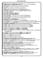
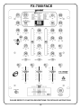
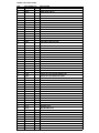
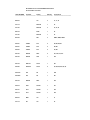
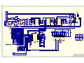
SERVICE MANUAL
FX-7000
PRO STEREO MIXER WITH DSP EFFECTS
CONTENTS:
Connections & Operations:.......................................................Page 2-6
Specifications:..............................................................................Page 6
Parts Lists:...............................................................................Page 7-12
PCBs:......................................................................................Page 13-16
Schematics:...........................................................................Page 17-24
Gemini Sound Products Corp.
120 Clover Place P.O. Box 6928
Edison, NJ 08818-6928
732-738-9003 (Phone) • 732-738-9006 (Fax)
(1)
QUICK START GUIDE:
1
2
3
4
5
6
7
8
9
10
11
12
13
14
15
16
17
18
19
20
21
22
23
24
25
26
27
28
29
30
31
32
33
34
35
36
37
38
39
40
41
42
43
44
45
46
47
48
49
50
51
52
53
54
55
56
57
AC 15V: Use this input to connect the power, plug the adapter into an outlet and the AC 15V (1) input.
POWER: To turn on the POWER (2), press this switch once.
BALANCED OUTPUT: Use the BALANCED OUTPUT (3) to connect to your amplifiers BALANCED input.
MASTER OUTPUT: An unbalanced output to connect to your amplifiers input.
ZONE OUTPUT: Connect this line to an additional amplifier or powered speakers.
REC OUTPUT: To record a mix, connect this line to a recording device.
SEND: An output used to send your mix to an outboard signal processor.
RETURN: An input that receives a signal from your outboard signal processor.
LINE 5 INPUT: To connect any line in devices, such as a CD Player, DAT, MiniDisc, etc.
PH3/L4 INPUT (PHONO3/LINE4): To connect a TURNTABLE or LINE input into the mixer.
LINE 3 INPUT: SEE LINE 9
PH2/L2 INPUT (PHONO2/LINE2): SEE LINE 10
PH1/L1 INPUT (PHONO1/LINE1): SEE LINE 10
MIC 2: Plug in your second MICROPHONE here.
PHONO/LINE SWITCH: Controls what kind of device is heard on the PH3/L4 (10) input.
PHONO/LINE SWITCH: Controls what kind of device is heard on the PH2/L2 (12) input.
PHONO/LINE SWITCH: Controls what kind of device is heard on the PH1/L1 (13) input.
GROUND SCREW: Connect your ground wire from your turntable here.
MIC 1: Plug in the main MICROPHONE here.
HEADPHONES: Plug in your HEADPHONES in here, to listen to your mix.
CROSSFADER CURVE: Pressing this button changes the CROSSFADER (23) curve from gradual to sharp.
X-FADER ASSIGN: Use to select CHANNEL 1 or 2, for which channel is assigned to the left side of the CROSSFADER (23).
CROSSFADER: Shifting the CROSSFADER (23) from left to right will enable you to mix different channels.
CROSSFADER REVERSE SWITCH: This reverses the location of the channels assigned to the CROSSFADER (23).
DSP EFFECT: Press DSP EFFECT (25) to turn the effect on or off that is being chosen.
CHANNEL 1 SLIDE: Moving this slide up or down raises and lowers the volume for CHANNEL 1.
CHANNEL 2 SLIDE: Moving this slide up or down raises and lowers the volume for CHANNEL 2.
CHANNEL 3 SLIDE: Moving this slide up or down raises and lowers the volume for CHANNEL 3.
CUE CH1: Press CUE CH1 (29) to hear CHANNEL 1 thru the HEADPHONES.
CUE CH2: Press CUE CH2 (30) to hear CHANNEL 2 thru the HEADPHONES.
CUE CH3: Press CUE CH3 (31) to hear CHANNEL 3 thru the HEADPHONES.
CUE EFF: Press CUE EFF (32) to hear the effect that is being applied to CHANNELS 1-3, MIC 1 or the MASTER (PGM)
with the HEADPHONES.
CH-1 SWITCH: Flipping this switch changes the CHANNEL 1 input from MIC 2 to PH1/L1.
CH-2 SWITCH: Flipping this switch changes the CHANNEL 2 input from PH2/L2 to L3.
CH-3 SWITCH: Flipping this switch changes the CHANNEL 3 input from PH3/L4 to L5.
LOW: Controls the LOW (Bass) range for the channels.
MID: Controls the MID (Middle) range for the channels.
HIGH: Controls the HIGH (Treble) range for the channels.
GAIN: Controls the overall volume GAIN for each of the channels.
VU METER: The VU METER (40) displays the LEFT & RIGHT CHANNEL levels or the CUE and PGM.
VU METER MODE: Press VU METER MODE (41) button to change the VU METER (40) mode.
CUE SPLIT: Pressing CUE SPLIT (42) lets you hear the CUE on the left side earphone and the PGM on the right side.
CUE-PGM: Turning CUE-PGM (43), from left to right changes the monitored CUE to PGM (MASTER).
CUE LEVEL: CUE LEVEL (44) controls the level of the CUE.
MASTER: MASTER (45) controls the level of the MASTER OUTPUT (4) & BALANCED OUTPUT (3).
ZONE: ZONE (46) controls the level of the ZONE OUTPUT (5).
MIC 1/TALKOVER: MIC 1/TALKOVER (47) switch activates MIC 1 (19) and TALKOVER.
MIC 1/TALKOVER LED: The MIC 1/TALKOVER LED (48) glows when the MIC 1/TALKOVER (47) switch is on.
MIC1 LEVEL: MIC 1 LEVEL (49) controls the volume of MIC 1 (19).
LOW: For adjusting the BASS level on MIC 1 (19).
HIGH: For adjusting the TREBLE level on MIC 1 (19).
CHANNEL SELECTOR: Moving the CHANNEL SELECTOR (52) will assign CHANNELS 1-3, MIC 1 or the MASTER
(PGM) that the DSP SIGNAL PROCESSOR is affecting. Use CUE EFF (32) to hear the effect before pressing.
EFFECT SELECTOR: Turn this knob to select 1-16 effects.
DSP EFFECTS: Here is the list of effects, refer to DSP SIGNAL PROCESSOR section for details.
PARAMETER LED DISPLAY: PARAMETER LED DISPLAY (55) displays the chosen effect and the parameters.
PARAMETER KNOB: PARAMETER (56) knob changes the parameters (1-99) of the chosen effect.
WET/DRY: Turning the WET/DRY (57) knob lets you activate the effects signal in and out of the mix.
(2)
FX-7000 FACE
PLEASE REFER TO FUNCTION DESCRIPTIONS FOR DETAILED INSTRUCTIONS
(3)
FX-7000
FRONT AND BACK PANEL
FRONT
BACK
PLEASE REFER TO CONNECTIONS SECTION FOR DETAILED INSTRUCTIONS
(4)
6. The MIC 1 (19) input (found on the front panel) accepts a 1/4" connector.
The MIC 2 (14) input (found on the rear panel) accepts 1/4" connector.
They both accept BALANCED or UNBALANCED microphones.
INTRODUCTION:
Congratulations on purchasing a Gemini FX-7000 DSP EFFECTS
mixer. This state of the art mixer is backed by a three-year warranty,
excluding crossfader and channel slides. Prior to use, we suggest that
you carefully read all the instructions.
OPERATION:
1. POWER ON: Once you have made all the equipment connections to
your mixer, press the POWER SWITCH (2). The power will turn on and
the VU METER (40) LEDS will glow.
FEATURES:
• 14 Variable Effects: Delay, Echo, Reverb, Pitch Shifters,
Filters, Brake, Auto-Pan, Flanger, Phaser, Rotary, Ambient,
& 9 Additional Preset Reverbs
• Parameter Adjustment & LED Display for easy Effect Settings
• Wet/Dry Adjustment Knob for Proper Program/Effect Mix
• Reversible Crossfader and Curve Switch
• Crossfader with a RAIL-GLIDETM Fader
• 3 Channel DSP 10" Mixer
• 3 Phono/5 Line/2 Mic Inputs
• Effect Loop Send & Return
• Mic with Talkover
• Split Cueing
2. CHANNEL 1: The GAIN (39), HIGH (38), MID (37), and LOW (36)
controls allows you to fully adjust the selected source. CH-1 SWITCH
(33) allows you to select either the MIC 2 (14) or the PHONO 1/LINE 1 (13)
input. The CHANNEL 1 SLIDE (26) controls the output level of this channel.
3. CHANNEL 2: The GAIN (39), HIGH (38), MID (37), and LOW (36)
controls allows you to fully adjust the selected source. CH-2 SWITCH
(34) allows you to select the PHONO 2/LINE 2 (12) or the LINE 3 (11)
input. The CHANNEL 2 SLIDE (27) controls the input level of this channel.
CAUTIONS:
4. CHANNEL 3: The GAIN (39), HIGH (38), MID (37), and LOW (36)
controls allows you to fully adjust the selected source. CH-3 SWITCH
(12) allows you to select the PHONO 3/LINE 4 (10) or the LINE 5 (9)
input. The CHANNEL 3 SLIDE (28) controls the input level of this channel.
1. All operating instructions should be read before using this equipment.
2. To reduce the risk of electrical shock, do not open the unit. There are,
NO USER REPLACEABLE PARTS INSIDE. Please refer servicing to a
qualified Gemini Sound Products service technician.
NOTE: THERE IS LOW, MID AND HIGH EQUALIZATION FOR EACH CHANNEL WITH AN
EXTREMELY WIDE RANGE OF ADJUSTMENT.
SUGGESTION: YOU CAN USE THE CUT FEATURES ON EACH CHANNEL TO REMOVE LOW,
MID AND/OR HIGH RANGE TO CREATE SPECIAL EFFECTS.
In the USA: If you experience problems with this unit, please call 1 (732) 738-9003 for Gemini
Customer Service. Do not attempt to return this equipment to your dealer.
4. This unit should be cleaned only with a damp cloth. Avoid solvents or
other cleaning detergents.
5. CROSSFADER CURVE: The CROSSFADER CURVE (21) button allows
you to adjust the kind of curve the crossfader has. Depress the
CROSSFADER CURVE (21) button
to make the curve steep and
cutting (perfect for scratching). Release the CROSSFADER CURVE
to make the curve gradual and gentle.
(21) button
5. When moving this equipment, it should be placed in its original carton
and packaging. This will reduce the risk of damage during transit.
6. X-FADER ASSIGN: The X-FADER ASSIGN (22) enables you to set the
left side of the crossfader to either CHANNEL 1 or 2.
6. DO NOT EXPOSE THIS UNIT TO RAIN OR MOISTURE.
7. CROSSFADER SECTION: The CROSSFADER (23) allows the mixing
of one source into another. The left side of the CROSSFADER (23) is
CHANNEL 1 or 2 and the right side is CHANNEL 3. The CROSSFADER
(23) in your unit is removable and if the need arises can be easily
replaced. Your Gemini mixer comes with an RG-45 PRO
(RAILGLIDE™) Dual-Rail Crossfader. RAIL GLIDE™ crossfaders
have internal dual stainless steel rails that allow the slider to ride
smoothly and accurately from end to end. Also available is our CF-45
PRO (PROGLIDE™) Dual-Rail Crossfader. This unique crossfader
features, state of the art conductive plastic technology, for unlimited
usage. Another crossfader we have available is the PSF-45 (PRO
SCRATCH™) crossfader with a special curve designed for scratch
mixing. Just purchase one from your Gemini dealer and follow the
instructions:
3. Do not expose this unit to direct sunlight or to a heat source such as a
radiator or stove.
7. DO NOT USE ANY SPRAY CLEANER OR LUBRICANT ON ANY
CONTROLS OR SWITCHES.
CONNECTIONS:
1. Before plugging the adapter in the AC 15V (1) input, make sure that the
POWER (2) switch is in the off position. The VU METER LEDS (40) will
be off.
2. The FX-7000 is supplied with 4 sets of output jacks:
• The 1/4" BALANCED OUTPUT (3) jacks are used to connect to your
main amplifier using standard balanced cables. We recommend using
BALANCED OUTPUT (3) if the cables to your amp are 25 feet or more.
• The MASTER OUTPUT (4) (RCA type) jacks are unbalanced and used
to connect to your main amplifier.
• The ZONE OUTPUT (5) (RCA type) jacks allow you to hook up an
additional amplifier.
• The REC OUTPUT (6) (RCA type) jacks can be used to connect the mixer to
the record input of your recorder enabling you to record your mix.
1. Unscrew the outside FADER PLATE SCREWS (B).
Do not touch the INSIDE SCREWS (C).
2. Carefully lift the fader and unplug the CABLE (D).
3. Plug the new fader into the cable and place it back in
the mixer.
4. Screw the fader to the mixer.
3. The FX-7000 also has an effect SEND (7) output and RETURN (8) input,
for use with an outboard processor or effects unit.
8. CROSSFADER REVERSE SWITCH: The CROSSFADER REVERSE
SWITCH (24) allows you to reverse the crossfader so that the left side
of the crossfader controls CHANNEL 3 and CHANNEL 1 or 2 is
controlled by the right side of the crossfader.
4. On the rear panel are 3 STEREO PHONO/LINE INPUTS (10, 12, 13)
and 2 STEREO LINE INPUTS (9, 11). The PHONO/LINE SWITCH (15)
enables you to set the PHONO 3/LINE 4 INPUT (10) to PHONO or LINE.
The PHONO/LINE SWITCH (16) enables you to set the PHONO 2/LINE 2
INPUT (12) to PHONO or LINE. The PHONO/LINE SWITCH (17)
enables you to set the PHONO 1/LINE 1 INPUT (13) to PHONO or LINE.
The PHONO inputs will accept only turntables with a magnetic cartridge.
A GROUND SCREW (18) for you to ground your turntables is located on
the rear panel. The STEREO LINE INPUTS (9, 11) will accept any line
level input such as a CD, DAT, MiniDisc, etc.
NOTE: WHEN THE CROSSFADER REVERSE SWITCH (24) IS ACTIVATED, ONLY THE CROSSFADER
REVERSES. THE CHANNEL SLIDES, GAIN, AND TONAL CONTROLS DO NOT REVERSE.
9. OUTPUT CONTROL SECTION: The level of the MASTER OUTPUT (4)
& BALANCED OUTPUT (3) are controlled by the MASTER (45) control.
The ZONE (46) control adjusts the level of the ZONE OUTPUT (5).
HINT: ZONE OUTPUT (5) IS USED BY SOME DJS TO RUN MONITOR SPEAKERS IN THE DJ
BOOTH. YOU CAN ALSO USE IT AS A SECOND ZONE OR AMP OUTPUT.
5. Headphones can be plugged into the front panel mounted HEADPHONES
(20) jack.
NOTE: THE RECORD OUT (6) HAS NO LEVEL CONTROL. THE LEVEL IS SET BY THE
CHANNEL SLIDES AND THE GAIN CONTROLS OF THE SELECTED CHANNEL. TONAL
QUALITIES ARE SET BY THE LOW, MID AND HIGH CONTROLS OF THE SAME CHANNEL.
(5)
10.MIC 1/TALKOVER: The purpose of the TALKOVER section is to allow
the program playing to be muted so that the MIC can be heard above
the music. The MIC 1/TALKOVER SWITCH (47) controls MIC 1 (19)
and has three settings. When the MIC 1/TALKOVER SWITCH (47) is
in the “OFF” position, MIC 1 and TALKOVER are off. When the MIC/
TALKOVER SWITCH (47) is in the “MIC 1” position MIC 1 is on, the
MIC/TALKOVER LED (48) will glow, but TALKOVER is off. When the
MIC/TALKOVER SWITCH (47) is in the “TALKOVER” position, MIC 1
and TALKOVER will be on and the volume of all sources except the
MIC 1 input are lowered by 16 dB. The HIGH (51) and LOW (50)
CONTROLS allow you to fully adjust the tone of MIC 1. MIC 1 LEVEL
(49) controls the level of MIC 1.
12. FLANGER: Flanger sound is an effect, which is often referred to as a
“whooshing” or “airplane fly-by” sound, turning knob clockwise
increases the intensity of the effect.
11.CUE SECTION: By connecting a set of headphones to the
HEADPHONE (20) jack, you can monitor any or all of the channels.
Press the CUE ASSIGN BUTTONS (29, 30, 31,) for CHANNELS 1-3 to
select the channel or channels to be monitored and the buttons will
illuminate. Use the CUE LEVEL (44) control to adjust the headphone
volume without affecting the overall mix. By rotating the CUE PGM
PAN (43) control to the left you will be able to monitor the assigned cue
signal. Rotating to the right will monitor the PGM (program) output.
Pressing the CUE SPLIT (42) button lets you hear the CUE on the left
side earphone and the PGM (program) on the right. Pressing the CUE
EFFECT (32) button allows you to send your EFFECT output to your
CUE MIX.
PARAMETER LED DISPLAY (55): The PARAMETER LED DISPLAY (55)
displays which effect is chosen as well as the parameters.
13. PHASER: Very close to flanger, phaser is a similar but different effect.
14. ROTARY: Simulates a rotating speaker effect.
15. AMBIENCE: Adds ambient effect to mix.
16. PRESET REVERBS: F1. HALL 1, F2. HALL 2, F3. ROOM 1, F4. ROOM 2,
F5. ROOM 3, F6. PLATE 1, F7. PLATE 2, F8. PLATE 3, F9. ROOM CHORUS
PARAMETER (56): The PARAMETER (56) knob changes the effects
parameters from (1-99), except for effect number 1. However effect
number 16, has 9 different preset reverb settings (F1- F9).
WET/DRY (57): Turning the WET/DRY (57) knob lets you pan the selected
effect into and out of the PGM (program)
SPECIFICATIONS:
AUDIO SECTION:
INPUT TERMINAL (input level/impedance) @ gain max.:
LINE 1, 2 , 4.....................................................................................................................-20dB(100mV) 47 KOhm
LINE 3, 5............................................................................................................................-20dB(100mV 13 KOhm
PHONO 1, 2, 3...................................................................................................................-54dB(2mV) 47 KOhm
MIC 1, 2...........................................................................................................-56dB(1.5mV) 2 KOhm (Balanced)
RETURN.........................................................................................................................-20 dB (100mV) 5 KOhm
OUTPUT TERMINAL (output level/impedance):
MASTER OUTPUT (RCA)..................................................................................................0 dBV (1V) 300 Ohm
MASTER OUTPUT (1/4" BALANCED)..............................................................................6 dBV (2V) 600 Ohm
REC OUTPUT .................................................................................................................-18dB(120mV) 5 KOhm
ZONE MONITOR..................................................................................................................0 dBV (1V) 300 Ohm
SEND.................................................................................................................................-18dB(120mV) 2 KOhm
PHONES..................................................................................................................................0 dBV (1V) 47 Ohm
12.VU METER MODE: The peak hold, dual function VU METER (40)
indicates either the MASTER (38) output left and right levels, or the
CUE and PGM (program) levels. You can choose the option you want
by pressing the VU METER MODE (41) button.
DSP SIGNAL PROCESSOR:
DSP EFFECT (25): Tap the DSP EFFECT (25) button to turn ON or turn
OFF the desired effect.
FREQUENCY CHARACTERISTICS:
CHANNEL SELECTOR (52): The channel selector is for selecting the
channel you want the effect to have effect on. Use the CHANNEL
SELECTOR (52) to select CHANNELS 1, 2, 3, MIC 1, or the MASTER
output. To hear it before you mix it in the PGM (program) use the
CUE EFFECT (32) button.
LINE/MIC..........................................................................................................................20Hz – 20 kHz (+/-2dB)
PHONO (RIAA)...............................................................................................................................20Hz – 20 kHz
SN RATIO (with effect off)............................................................................................................ better than 80dB
TOTAL HARMONIC DISTORTION.....................................................................................rate less than 0.02%
CHANNEL EQUALIZER (LINE, PHONO, MIC 2);
HI.......................................................................................................................................................+12 dB, -32 dB
MID...................................................................................................................................................+12 dB, -32 dB
LOW..................................................................................................................................................+12 dB, -32 dB
MICROPHONE EQUALIZER (MIC 1):
HI.......................................................................................................................................................+12 dB, -12 dB
LOW..................................................................................................................................................+12 dB, -12 dB
TALKOVER ATTENUATION...........................................................................................................................16dB
EFFECT SELECTOR (53): Turning this knob selects the effect (1-16);
refer to D.S.P. EFFECTS (54) for which effect you want to use.
Displayed by the PARAMETER LED DISPLAY (55). The effects
parameters (1-99) can be adjusted using the PARAMETER (56) knob.
ELECTRICAL SECTION, ETC.:
POWER SUPPLY VOLTAGE...........................................................................AC 18 V, 50-60 Hz (from adapter)
POWER CONSUMPTION.............................................................................................................................20 W
OPERATING TEMPERATURE...............................................................................+5C to +35C (+41F - +95F)
OPERATING HUMIDITY.......................................................................................................................5% to 85%
EXTERNAL DIMENSIONS........................................254(W) 355 (D) 110 (H) mm/10(W) 14 (D) 4-1/3(H) in.
WEIGHT..............................................................................................................................................8 lbs/3.7 Kgs
ACCESSORIES:............................................................................................................Power Adapter
DSP EFFECTS (54): All the DSP effects are listed on the mixer here.
Turning the PARAMETER (56) knob clockwise increases the effect in
most cases. Here is a brief explanation of their uses:
01. SEND/RETURN: Used to connect outboard effect units.
02. DELAY: Delay effect; adjust time with PARAMETER (56) knob.
03. ECHO REGULAR: Echo effect, adjust time like delay effect.
04. PING PONG ECHO: Echo effect with left/right panning, adjust time
like delay effect.
05. REVERB: Reverb effect for depth, adjust time just like delay effect.
06. PITCH UP: Increases the pitch of the selected CHANNEL, Mic 1 or
MASTER (PGM).
07. PITCH DOWN: Decreases the pitch of the selected CHANNEL, MIC 1
or MASTER (PGM).
08. FILTER 1: Low pass filter increases with clockwise knob movement.
09. FILTER 2: High pass effect increases with clockwise knob movement.
10. BRAKE: Simulates the manual stop of a record on a turntable.
11. AUTO PAN: Automatic panning from left to right, turning knob
clockwise increases the effect speed.
(6)
CABINET PARTS AND PACKING
ITEM
PART NUMBER Q'ty
ENGLISH NAME
1
012-073
1
PANEL CONTROL
3
034-153
1
PANEL, REAR
4
032-171
1
COVER, BOTTOM
5
022-392
1
HOLDER, FADER
7
8
023-674
4
KNOB SWING
9
002-589
1
PUSH KNOB -WHITE
10
002-531
2
KNOB PUSH (SMALL)
11
002-532
1
KNOB PUSH BUSHING (SMALL)
12
002-585
5
KNOB PUSH
15
002-724
4
KNOB SLIDE (BIG)
003-171
11
KNOB ROTARY (A)
16
17
18
003-172
5
KNOB ROTARY (B)
19
003-173
3
KNOB ROTARY (C)
20
003-174
1
KNOB ROTARY (D)
21
003-175
3
KNOB ROTARY (E)
255-291
1
GIFT BOX
22
25
42
43
257-036
1
OWNER'S MANUAL
44
153-237
1
POLYFORM
45
END CABINET PARTS
10
11
074-145
5
INTEGRATED CIRCUIT NJM2068LD
12
074-104
1
INTEGRATED CIRCUIT NJM4558LD (M5218AL,BA4558N)
13
074-113
1
INTEGRATED CIRCUIT NJM4556L
14
074-166
1
INTEGRATED CIRCUIT LB1482M
15
074-107
1
INTEGRATED CIRCUIT NJM7812FA
16
074-114
1
INTEGRATED CIRCUIT NJM7912FA
17
074-074
1
INTEGRATED CIRCUIT NJM7805FA
18
074-211
1
INTEGRATED CIRCUIT NJM79L08A
19
074-212
1
INTEGRATED CIRCUIT NJM78L08A
20
074-216
1
INTEGRATED CIRCUIT W78E58B-40
21
074-210
21
INTEGRATED CIRCUIT NJM2068MD
22
074-213
1
INTEGRATED CIRCUIT TB62706BF
23
074-214
1
INTEGRATED CIRCUIT TC4052BFN
24
074-215
6
INTEGRATED CIRCUIT TC4053BFN
26
074-207
1
INTEGRATED CIRCUIT AL1101
27
074-208
1
INTEGRATED CIRCUIT AL1201
28
074-209
1
INTEGRATED CIRCUIT AL3201
30
076-104
1
TRANSISTOR 2SA1048 (2SA1317)
31
076-095
6
TRANSISTOR 2SC2878
32
076-002
1
SILICON TRANSISTORS 2SC945 (Q)(P)
33
076-003
25
29
SILICON TRANSISTORS OR 2SC1815 (Y)(GR)
34
35
079-027
6
RECTIFIER DIODE 1N4002
36
079-003
33
37
079-021P
7
SILICON DIODE 1N4148
ZENER DIODE 1/2W 3V (
¢ªBZX79C3V0)
CABINET PARTS AND PACKING
¢ªBZX79C3V3)
ITEM
PART NUMBER Q'ty
38
079-056P
7
ENGLISH NAME
ZENER DIODE 1/2W 3.3V (
39
079-058
1
ZENER DIODE 1/2W 16V
41
052-019
1
CERAMIC RESONATOR 33.86MHz
42
058-023
1
CRYSTAL OSCILLATOR 8MHz
44
059-216
1
AC ADAPTER AC120V 60Hz/AC 18V 750mA
45
059-217
AC ADAPTER AC230V 50Hz/AC 18V 750mA
46
059-218
AC ADAPTER AC240V 50Hz/AC 18V 750mA
40
43
47
48
092-134
1
TELEPHONE JACK 6P6C
49
092-128
1
IC SCOKET 40P
50
51
081-051
2
SLIDE SWITCH 4P2C FD-ASSIGN,REVERSE SW
52
081-004
3
SLIDE SWITCH 2S6P PH/LN SW
54
082-048
1
ROTARY SWITCH L=22.5 CH SELECTOR
55
082-049
1
ROTARY SWITCH 1P16C L=16.5 EFF SELECTOR
56
082-006
1
TACT SWITCH
57
082-019
3
LEVER SW 4P2C P=18
58
082-022
1
LEVER SW 4P3C P=24 PGM
60
083-123
1
ROTARY ENCODER
61
083-069
4
PUSH SWITCH 2P2C L=12.5 CUE1-3 SW
53
59
62
083-097
2
PUSH SWITCH 4P2C L=12.5 CUE/SPLIT,DISP MODE
63
083-110
1
PUSH SWITCH 4P2C L=12.5 FADER CURVE
64
083-111
1
POWER SWITCH UL
66
071-239
2
ROTARY VR L=22.5 20KA MICTONE/HI LOW
67
071-240
1
ROTARY VR L=22.5 250KA×2 MIC LEVEL
68
071-166
4
ROTARY VR L=22.5 50KA×2 CH2,3 CUE,GAIN,MASTER
69
071-167
9
ROTARY VR L=22.5 50KE×2 CH HIGH MID BASS
65
70
071-168
1
ROTARY VR L=22.5 10KA×2 ZONE
71
071-204
1
ROTARY VR L=22.5 50KB CH1 GAIN
73
071-222
1
ROTARY VR L=22.5 20KB×2 CUE PGM
74
071-241
1
ROTARY VR L=22.5 10KB×2 FX LEVEL
76
072-122
3
SLIDE VR 45mm L=20 10KA×2 CH-VOL
77
072-113
1
SLIDE VR 45mm L=20 100KB×2 FADER
79
080-106
8
LED (RED) 3.15!
80
080-113
8
LED (RED) 2.2×3.0
72
75
78
81
080-115
4
LED (YELLOW) 2.2×3.0
82
080-114
12
LED (GREEN) 2.2×3.0
83
080-125
1
LED (RED) 2.2×3.0
84
080-123
1
LED NUMERIC DISPLAY
86
092-078
5
PHONE JACK 6.3!
87
161-165
3
4P RCA JACK
88
161-166
1
6P RCA JACK
89
161-174
1
2P RCA JACK
85
Bill Of Material For D:\FX-7000\NEW\FX7000-1.PCB
On 5-Dec-2002 at 07:38:53
PART NUMBER
-------------------------
Comment
-------------------------
Pattern
---------------------------
Quantity
--------------
Components
---------------------------------------------
082-019
LBC42B
3
SW5, SW7, SW10
082-022
LBC43
1
SW2
081-051
MISAKI1
2
SW1, SW8
082-006
PB
1
SW14
083-069
SPEC12HB07
4
SW3, SW6, SW9, SW13
083-097
SPEC14HB
2
SW11, SW12
083-110
SPUN4/2_BOR
1
SW4
072-113
100KBX2
TOKYO-ALPHA
1
X1_1
071-168
10KAX2
RK14K124
1
VR19
072-091
10KAX2
VR45D
3
VR8, VR13, VR18
079-003
1N4148
D6
6
D12, D15, D17, D18, D19, D20
074-210
2068MD
DMP8
16
IC1, IC2, IC3, IC5, IC6, IC8,
IC9, IC10, IC11, IC12, IC13,
IC14, IC16, IC17, IC18, IC19
071-239
20KA
RK11K114
2
VR1, VR2
071-222
20KB
RK14K124
1
VR22
071-240
250KA
RK11K114
1
VR3
076-002
2SC1815
TO-92
1
Q1
079-021P
3V0
D6
4
D4, D7, D10, D34
079-056P
3V3
D10
2
D6, D33
079-056P
3V3
D7.5
2
D3, D9
074-113
4556L
SIP8
1
IC15
071-166
50KAX2
RK14K124
3
VR9, VR14, VR21
071-166
50KAX2
RK14K124
1
VR20
071-204
50KB
RK14K124
1
VR4
071-167
50KE
RK14K124
9
VR5, VR6, VR7, VR10, VR11, VR
VR15, VR16, VR17
074-212
78L08A
TO-92
1
IC4
074-211
79L08A
TO-92
1
IC7
080-106
LED
LED
6
D1, D2, D5, D8, D14, D16
080-125
LED(RED)
LED
1
D11
074-214
TC4052B
SO-16
1
U4
074-215
TC4053B
SO-16
5
U1, U2, U3, U5, U6
Bill Of Material For D:\FX-7000\NEW\FX7000-3.PCB
On 5-Dec-2002 at 07:38:53
PART NUMBEComment
Pattern
Quantity
-----------------------------------------------------------------------------
Components
-----------------------------------------------------------
080-114
GRN
LEDREC
12
D6, D7, D8, D9, D10, D12,
D18, D19, D20, D21, D22,
D24
074-166
LB1482
LB1482
1
IC1
080-113
RED
LEDREC
8
D1, D2, D3, D13, D14, D15,D11,D23
080-115
YLW
LEDREC
4
D4, D5, D16, D17
Bill Of Material For D:\FX-7000\NEW\FX7000-2.PCB
On 5-Dec-2002 at 07:38:53
PART NUMBER Comment
Pattern
Quantity
----------------------- ----------------------- ---------------------------------
Components
--------------------------------------------------------
083-123
ENCODER
1
EC1
071-241
10KBX2
RK14K124
1
VR1
079-058
16V
D12.5
1
D10
079-003
1N4148
D10
1
D12
079-003
1N4148
D6
24
D1, D2, D3, D4, D5, D6, D7, D8,
D9, D13, D14, D15, D16, D17, D18,
D19, D20, D21, D22, D23, D24,
D26, D27, D28
074-210
2068MD
DMP8
5
IC1, IC2, IC3, IC5, IC6
052-019
33.86MHz
CRYSTAL
1
Q2
079-021P
3V0
D12.5
1
D30
079-021P
3V0
D6
1
D32
079-056P
3V3
D6
2
D29, D31
058-023
8.000MHz
CRYSTAL
1
Q1
074-207
ADC
ADC
1
U1
074-208
DAC
DAC
1
U4
074-209
DSP
DSP
1
U2
080-123
LED_DISP
LED_DISP
1
LED1
080-123
P87C58
DIP40
1
U3
082-049
RSW16
SR3012-16
1
SW1
082-048
SR1712
SR1712
1
SW2
074-213
TB62706
TB62706
1
IC4
074-215
TCC4053B
SO-16
1
U5
Bill Of Material For D:\FX-7000\NEW\FX7000-5.PCB
On 5-Dec-2002 at 07:38:53
PART NUMBER
Comment
Pattern
Quantity
------------------------- ------------------------- -----------------------------------------
Components
--------------------------------------------
092-078
1/4"
3
J1, J7, J9
161-174
2RCA-N
1
J2
161-165
4RCA-N
3
J3, J4, J5
092-134
6P6C
1
J8
161-166
6RCA-N
1
J6
081-004
SS7
3
SW01, SW02, SW03
079-027
1N4004
D10
4
D3, D4, D6, D7
079-027
1N4004
D7.5
2
D5, D8
079-003
1N4148
D10
2
D1, D2
074-145
2068LD
SIP8
4
IC1, IC2, IC3, IC4
074-145
2068LD
sIP8
1
IC5
076-104
2SA1317
TO-92
1
Q4
076-095
2SC2878
TO-92
6
Q1, Q2, Q3, Q5, Q6, Q7
079-021P
3V0
D6
1
D10
079-056P
3V3
D6
1
D9
074-104
4558LD
SIP8
1
IC6
074-074
7805
TO-220
1
IC7
074-107
7812
TO-220
1
IC9
074-114
7912
TO-220
1
IC8
092-078
MIC1
1/4"
1
J1
161-174
PH
1/4"
1
J2
1
2
3
4
D
D
8
+12V
1+
2
C52
5K1
R59
47K
IC5A
2068LD
1C53
270P
1L
RETURN
D9
3V3
3
10/16
1+
R65
47K
4
10/16
J5A
C55
1
R60
C60
22/16
C56
22/16
1G
6
C54
C58
X7
10/16
IC5B
2068LD
1
R66
47K
4
C57
270P
-12V
300
X1
RETURN_LEFT
2
1
RETURN_RIGHT
3
2
R69
-12V
R71
47K
+12V
2G
SEND
300
4
16
15
17
14
18
13
47/10
EFF_IN_RIGHT7
10/16
EFF_IN_LEFT 8
EFF_OUT_LEFT
EFF_OUT_RIGHT
C59
EFF_IN_LEFT
EFF_IN_RIGHT
R74
47K
2K
R218
6K2
R217
30K
150
68K C3 19
12
223
11
20
+12V
MR C170
2
1
C76
22/16
C69
22/16
C77
22/16
10/16
CUE / MASTER
C168
SW2B
SW2A
1
3
30K 1%
C17
3
22/16
2
2
1
1
R23
SW13A
MIC_OUT
VR2
20KA
VR1
20KA
R168
22/16
2068MD
22/16
4
14C19 R16
101 30K 1%
R165
R
IC2A
R22
680
25
6
D20
D9
D21
D10
D22
R13 47K
SW12B 5
R8
180
3
3
4
4
10/10
26
5
27
4
28
3
4
R9
180
SW12A
C
1
FX7000-3
D11
LED
D11
D23
D24
D12
LED
LED
LED
LED
R14
X12
+5V
180
Q1
2SC1815
R193
C171
4.7/16V
3K
1
12-
SW13B
D16
LED
2
30
LB1482
2
36K
29
R227
1K2
D12
1N4148
D20
180
+12V
1N4148
12+
R10
R191
5K1
R204
100K
C13
22/16
C9
124
C15
2
3
C14
22/16
R166
C16
684
IC2B
2068MD
2
C5
9
36K
5
1K 1%
22/16
C20
FX7000-1
36K
C1
124
PGM_R
R37
10
R159
4.7P
6K8
7
22/16
36K
R163
R
R2
51K
C11
-12V
14+
6
C10
123
R8
101
1K 1%
C18
FX7000-8
R20
4K7
C26
R13
X1
D19
D8
R7
2
PGM_L
+12V
R169
250KA
C2
8
X2
3
VR3
1
C31
22/16
T
R
S
7
6
1
R226
62K
C150
1N4148
D1
LED
3
8
24
+12V
5
2
2
1
C137
8
7
R14
MIC1
SW12C
D19
14D34
3V0
10/10
23
180
X2
1/16
L
7
1/16
4
C30
22/16
D18
D7
R6
8
6
14+
J1
X11
1
12
R167
100K
-12V
R38
4K7
9
180
5K1
R3
47K
10
22
SW12D
11
R175
22/16
D15
1N4148
D18
1N4148
C
C133
R
10
1N4148
CUE_R
R4
47K
D33
3V3
D17
D6
C4
R212
30K
CUE_L
C83
22/16
21
R11 47K
R211
6K2
R205
62K
3
4
9
D17
+12V
D16
D5
R5
150
X6
+5V
POWER FOR EFFECTS
D15
D4
R4
R12
10/16
C61
10/16
300
5
ML C166
R73
D14
D3
R3
+5V
C1
6
2R
D2
IC1
104
2K
2L
D13
R2
C2
J5B
2
D1
R1
5
5K1
R61
47K
FX7000-2
7
R62
10/16
1
1D10
3V0
8
1R
R36
10
R214
220
SW14
R198
-12V
4K7
8+ C44
D3
C68
33K
VR9A
8
50KA
12
10
C78
R28
100K
C21
C22
180
273
822
SW7B
1K8
2L
4R32
10
R37
11K
C32
101
C90
562
8K2
C88
R121
VR9B
+12V
50KA
10/16
11K
16
O/IB
CX
CY
A
B
C
O/IC
16
7
R97
33K
22/16
IC10B
2068MD
B1
8
R9
470K
10/16
10KAX2
R89
R108
33K
50KE
C82
562
IC11B
2068MD
R95
8K2
11
10
9
C71
7
5
C79
50KE
5
3
-12V
6
103
33K
2
1
10/16
R96
C73
6
682
24K
B1
AX
AY
D5
LED
O/IB
R124
100K
CX
CY
A
B
C
O/IC
14
VR18A
C103
R125
36K
15
C53
1
19-
22/16
R127
C58
7
22/16
R129
100K
36K
INH
VCC
VEE
8
4
10/16
R60
R58
2K
24K
C48
R188
100K
1/16
IC6A
22- 2068MD
R61
470K
-12V
-12V
+12V
+12V
R56
R57
2K
24K
16K
1/16
IC6B
2068MD
R40
470K
CH_L
1
CH_R
10
C164
22/16
R51
10
2
19+
22+
C126
22/16
C34
22/16
C100
22/16
C36
22/16
-12V
C154
19-
6
R219
R53
10
5K1
J4B
2L
1K8
2
R55
11K
C50
101
C49
1
7R153
10
10/16
R148
1K6
VR14B
50KA
R149
R134
33K
2
R57
11K
22/16
C51
1
IC13B
2068MD
10/16
X5
X4
50KE
R150
33K
VR16B
B3
B1
6
R203
C101 -12V
7
C138
22/16
2
C148
10/16
5
IC18B CUE_R
2068MD
15K
C162
C33
1/16
1
15K
7
SW11C
8
2
10
C127
220/16
R162
-12V
C70
103
C98
103
C3
103
C57
103
C99
103
C125
103
C39
103
+12V
SW11D
11
12
2
3
3
4
4
5
5
6
6
+12V
-12V
SW?
-12V
+12V
X1
3
X13
D3
-8V
A
1N4004
IC9
C77
D6
1000/25
1N4004
7812
1
C84
104
R183
36K
D5
1N4004
+12V
Vin
C78
1000/35
Vout
3
C81
1/50
20KB
R185
15K
3
X14 X3
10/16
50KA
3
2
2
1
1
C147
47P
T
R
S
J2
PH
4
7
5
R181
C82
104
C76
IC15B
4556L
C80
1000/35
IC8
7912
2
Vin
-12V
3
+5V
D4
1
FX7000-9
1N4004
Vin
C79
470/25
IC7
7805
15K
L
3
C83
1/50
Vout
1N4004
6
47
R180
51K
D7
1N4004
D8
5
1000/25
6
C129
VR21B
3
SPLIT
2
+12V
1
10
IC15A
4556L
C38
1/16
Vout
C43
103
2
J8
20-
910
R184
VR22A
A2
15K
R224
20-
R172
C146
22/16
R
9
R174
15K
R173
Vin
IC7
79L08A
47
R197
51K
2
-12V
1
2
LED
R190
-12V
15K
4K7
11-
1
3
-12V
R177
10
1
D1
1N4148
X11
1
L
D14
R160
+12V
10
C130
220/16
20+
2
10/16
50KA
20KB
R209
R161
20+
C158
47P
SW11B
15K
R182
15K
10/16
-12V
FX7000-5
VR22B
6
R210
36K
C161
22/16
R216
5
7
R223
910
VR21A
R
B2
4
C135
22/16
5K6
SW11A
3
R164
15K
91K
6
11+
R152
1
101
R199
C104
682
R215
CUE/PGM
R189
15K
15K
R176
10
10/16
24K
10/16
+12V
5
R132
C149
-12V
1
GND
11C152
IC14B
2068MD
8K2
C105
50KE
CUE_L
IC18A
2068MD
C132
10/16
3
C134
R131
33K
11+
2
D10
3V0
C112
562
R138
C139
C163
10/16
1
B3
Vout
2
91K
10-
151
+8V
Vin
R200
C123
22/16
C110
3
X2
C120
22/16
103
B2
C115
2R
C48
101
+12V
IC4
78L08A
+12V
C153
101
D9
3V3
10/16
R136
VR15B
220/16
C64
+12V
1K5
C106
154
4K7
B1
R78
560K
1
1
B3
2K4
C114
1
10/16
R144
R133
154
R85
1K
D2
GND
R139
1K5
24K
VR17B
Q4
2SA1317
SW8B
8
R137
-12V
1K8
682
8
R135 B1
3K6
C107
50KE
1M
X10
5K6
2G
R58
10-
C124
24K
-12V
5K1
C102
1
3
R158
R77
IC16B
2068MD
36K
R179
3
8K2
C117
A1
101
-12V
R87
47K
R83
3K
2
R56
150
1
R49
10
C122
22/16
2
4
A
R157
33K
VR16A
50KE
C119
22/16
3
2
IC14A
2068MD
10+
2
10+
8K2
4
CH3_L
5
C116
562
R143
A3
7+
4
3
6
R154
10
4
4
8
822
R90
22/16
4
C38
273
C65
220
8
B1
100K
C39
180
6-
R80
IC16A
2068MD
1N4148
103
5
R43
R44
6
22/16
IC13A
2068MD
SW8C
A3
R151
33K
VR19B
C136
B3
C42
22/16
SW10B
2R
1
3
C67
4,7/16
5
A1
C109
7-
+12V
C46
22/16
J6B
2G
X-FADER
6
10/16
10KAX2
7
4
R45
13K
150
9
8
1R
3
1
R54
R84
R86
47K
16+
2
16-
-12V
56
R186
4
6
C44
22/16
SW10A
2
IC4B
2068LD
7
A1
101
B2
6+
5
1K
R142
2K4
C111
7+
2
4
C45
47P
R50
22/16
C144
A3
10
3
R51
47K
4
1L
1G
8
C36
47/16
J4A
R53
10
220
2L
SW8D
12
CH3_R
3
50KA
12
1
+12V
C66
36K
VR19A
C169
22-
R122
10
5
151
2
4
7
11
4K7
VR15A
50KE
1
4
VR14A
8
SW10D
R92
3K
R82
Q2
2SC2878
56
R201
11
4K7
1
3
Q7
2SC2878
R225
10
CH3_R
SW8A
10/16
10KAX2
-12V
C121
2
2
3
150
R110
47K
R24
C47
J7
T
R
S
R109
22/16
X7
R140
R155
3
1
2
R130
1K6
1K5
1
1
24K
9
22/16
2068LD
C37
47P
B
R105
220
16R141
10
CH3_L
2068MD
SW9B
D8
LED
R146
C113
154
2
R52
13K
6-
SW10C
R147
33K
154
8
3
1K
X9
4
R41
47K
X6
C47
R101
47K
C74
4
1
R42
1
IC4A
R145
1K5
8
6+
2
22/16
Q1
4
2
4
1
R128
A3
50KE
A2
8K2
A2
2
R47
100K
VR17A
R156 A1
3K6
C118
822
R46
A2
5
C41
273
47/16
B2
180
6
C72
2SC2878
VR18B
C108
R126
36K
8
C43
R48
3
6
R102
220
IC6B
4558LD
Q6
2SC2878
16+
10/16
10KAX2
36K
8
X5
5
L
C40
X03
3
6
5
10K
10K
C165
22/16
3
1
4
R208
10
21-
16K
SW4B
R123
3
3
4
5K6
R117
10
SW03B
IC17B
2068MD
R108
150
R50
10
-12V
-12V
SW03A
3
R100 3R
150
-12V
SW9A
5-
2
J6C
3L
150
101
R106
5K1
50KAX2
C22
22/16
R86
10
R45
IC12B
6
10/16
10KAX2
TC4053B
R115
2
R89
SW4A
5
4
21+
C6
22/16
18-
3
-12V
O/IA
R171
C142
R178
10
18+
C8
22/16
CH_R
22+
19+
2
R106
BX
BY
R21
10
C7
22/16
IC12A
SW6B
U6
12
13
8
VEE
VCC
16
7
8
16K
IC5B
2068MD
-8V +8V
C97
22/16
R94
1
2
J9
FX7000-7
+12V
4K7
D7
3V0
151
B3
R104
VR11B
B3
1/16
2068MD
C80
561
R187
820
C151
22/16
+12V
R88
10
SW4C
C95
22/16
94K7
B2
C89
24K
VR13B
C85
R92
36K
D6
3V3
R109
2K
R5
36K
1K5
C74
154
R90
VR10B
101
C94
22/16
10/16
682
4
4
8
4
CH_L
C35
9
22/16
R42
R7
100K 2068MD
15
4
R91
3K
X8
1
T
R
S
3G
8
5
R32
1
R104
47K
C73
13+
7
14
TC4053B
INH
4
2
7
9
GND
8
1
3
6
4
VEE
5
16
BX
BY
O/IA
X13
C145 MR
-12V
C143
22/16
9+
2K4
C87
C91
22/16
C35
1
R39
2
10/16 +12V
R100
B3
154
R113
C28
7
5K6
C75
50KE
5+
C33
101
C96
24K
A1
VR12B
B1
3K6
R101
1K5
R112
1K6
R118
10
1K8
11
10
9
C72
1
6
9-
VR11A
50KE
R98
R102
2R
R40
IC11A
2068MD
9+
2
3
2G
-12V
5
3
R114
33K
33K
A3
8K2
2
151
A3
R119
6
4
C34
1
2
1
103
B2
R38
J3B
A1
4K7
VR10A
50KE
R103
5
24K
C27
22/16
R107
C92
AX
AY
R221
10
R196
10
2
1
150
Q3
2SC2878
15-
+12V
3
2
BAL
R97
22/16
VR20B
8
IC10A
2068MD
C29
22/16
INH
X12
3
150
C68
GND
8
4+
6
R88
220
C128
22/16
A
TC4053B
B
C
X9
R95
15+
C131
22/16
10/16
IC19B
2068MD
R192
10K
GND
13K
22/16
C86
154
R116
101
5-
1
R35
R26
C30
22/16
50KE
154
12
13
4
4
Vout
GND
IC3B
2068LD
7
6
R25
10/16
R230
47K
C167
7
5
15
-12V
2
5
1K
1R
O/IC
13-
U5
1K5
6
C140
O/IB
CX
CY
R103
10
R170
10
4
1G
R36
10
3
2
R111
33K
14
Effect_in
O/IA
BX
BY
17-
Q5
2SC2878
3
R23
+12V
SW7A
4
2K7
R96
47K
4558LD
IC6A
2068MD
IC17A
+12V
2
4
C28
47P
9K1
IC1B
C29
10/16
6
-8V +8V
R110
A3
2K4
C84
5+
2
3
R33
47K
VR12A
R222
100K
C71
22/16
4
SW7D
11
4
1L
10/16
10KAX2
22/16
1
3
R206
C75
22/16
C70
17-
3
2
3
4
J3A
C174
10/16
16K
IC5A
2068MD
10K
15-
2
1
2
1
C19
47/16
21-
R30
470K
10/16
R194
36K
8
1
R99
1K6
9
22/16
2068LD
C26
47P
R105
1K5
24K
SW7C
7
13K
4-
1/16
8
3
1K
R19
C37
11
10
9
R98
220
1
R22
47K
X8
C31
5
3
17+
R93
1
50KAX2
C159 PGM_R
-8V +8V
AX
AY
2
1
17+
10K
15+
3
SW4D
SW06
1
1
R24
1
R94
X4
4
1
-12V
R34
24K
3
4+
2
R41
2K
2
4
eff_out
101
R99
5K1
2
C156
+12V
R120 A1
3K6
C93
IC3A
R31
4
8K2
22/16
6
R29
100K
18R6
100K 2068MD
VR13A
C81
R91
36K
5
R27
R229
10K
4
47/16
18+
2
4
8
180
12
13
C173
IC3B 10/16
2068MD
21+
3
INH
6
8
R30
O/IC
TC4053B
4
2
A
B
C
VCC
3
2
6
5
822
CX
CY
SW1C
IC1A
C27
1
820
VR20A
U2
+8V
SW6A
C24
273
11
10
9
R76
R93
A2
3
C25
682
O/IB
R34
27K
-12V
A2
1
SW02B
X3
5
3
C46
24K
BX
BY
10/16
IC19A
2068MD
R107
10
561
R202
R220
561
7
C24
10/16
+12V
13-
R195
10K
5K1
C157
1
3
4
1R
R81
10/16
C69
13+
2
15
10/16
INH
5
15
O/IC
16K
eff_out
27R6
10
A2
X02
R64
B1
6
8
3
C51
50KE
5K6
8
SW02A
10/16
8K2
VR6B
B3
R85
10
C3
22/16
IC1B
2068LD
2
VCC
R81
3-
C6
101
C23
2
1
CX
CY
R39
4K7
14
C63
C155 ML
C141
O/IB
A
TC4053B
B
C
6
C25
22/16
2K7
8
22/16
IC8B
2068MD
C60
22/16
C2
22/16
C5
22/16
R207
9K1
4
27+
47/16
C66
O/IA
C32
O/IA
BX
BY
GND
C42
22/16
R2
10
C7
2068LD
18K
SW1D
R43
-12V
AX
AY
GND
27-
4
MIC
R4
5K11 1%
C63
562
12
13
103
1
R7
1K 1%
-8V +8V
U3
IC9B
11
10
9
4
IC1A
3
C5
22/16
D2
LED
151
2068MD
5
3
R213
14
Effect_in
8
8
27+
2
J1
4K7
R69
eff_out
101
R17
8K2
10
C45
3+
R228
10K
9
8K2
R28
8K2
SW3B
C49
A3
R72
33K
IC3A 10/16
2068MD
12
11
R27
8K2
R26
12
5K11 1%
C56
154
R74
VR5A
50KE
2K4
1M
+12V
R1
1K 1%
A1
36K
11
101
R54
R47
10
10
R25
10/16
10KAX2
R44
1K5
154
R62
+12V
R3
C1
22/16
R55
1K5
5K6
C40
50KB
C4
101
B
R59
VR4B
R31
10
R77
B3
R75
33K
VR8B
C23
R49
36K
TC4052B
C52
50KE
33K
-12V
5K6
VR7B
B1
3K6
2
1
eff_out
SW2C
R63
8
R67
R66
12-
AX
AY
C172
16
8K2
4
4
R8
1K5
12+
2
3
VCC
100K
682
24K
VR6A
50KE
6
5
R5
1K5
SW1A
SHORTING TYPE
10
22/16
12
13
GND
47/16
R19
U1
16K
10/16
12
SW5B
20K
822
R17
R87
A1
C160
561
-8V +8V
R15
22/16
8
2-
R10
2068LD
C16
273
A3
8-
C67
18K
C4
22/16
C21
101
C12
R18
8K2
1
7
2
C15
C12
IC8A
2068MD
INH
R12
SW1B
VEE
1
1K
R
C20
22/16
10
C11
6
3
8K2
C55
PGM_L
R35
27K
13
8K2
8K2
SW3A
A
B
7
G
2+
C17
22/16
3-
11
IC2A
3
R84
33K
A2
R20
103
R70
R11
15
R1
8K2
36K
VEE
C10
47P
4
L
8
R21
10
22/16
14
R10
10/16
10KAX2
R46
11
C61
10
9
C65
1
3
8
5
2
12
8+
2
Y
4
5
1
SW5D
2068MD
C62
562
VR8A
C41
R48
36K
0Y
1Y
2Y
3Y
16
4
50KE
IC9A
VCC
3
4
3
R14
47K
1
5
2
4
151
7
3
1M
3+
R68
33K
GND
3
C64
B3
R79
47K
13
VEE
SW5A
2
1
R13
180
4K7
VR5B
B1
2K4
R80
2
C8
47P
+12V
J2
R82
154
R73
101
7
2
R52
1K5
5K6
C59
50KB
9
8
J6A
1L
16
GND
1
X
8
2-
1
20K
5K1
1G
0X
1X
2X
3X
SW2D
4
1K
X3
SW5C
R9
22/16
2068LD
4
R11
47K
R83
VR4A
X1
C9
7
8
33K
IC2B
2+
5
1K5
C54
154
8
822
6
12
14
15
11
4
273
R12
R79
33K
50KE
U4
8
180
4
C50
R76
47K
+8V -8V
4
47/16
R71
A2
1
8K2
B2
2
1
C14
A2
3
2
100K
C13
R75
10/16
3V0
22/16
R78
A3
B2
3
6
5
R18
B2
C18
VR7A
A1
B2
1
SW01B
X2
3K6
8
X01
R65
8
2
R16
22/16
R
R15
3
C62
-12V
3V3
7
+12V
SW01A
-12V
8- D4
X10
3
C85
1/50
PLUG02_MIN
1
2
3
4
X1
D
D
1
-12V+12V
R40 R41
820 820
RETURN
R37
-12V
+12V
10/16
+5
R11
R33
10K
C7
7
+5V
2068MD
C45
10/10
10/10
C1
R1
-5
IC5B
2K4
+1
R2
8
9
+5V
2068MD
7K5
R47
IC1A
R3
1 R4
10K
3
R56
1K5
8
4K7
B2
C43
R57
1
IC6B
27K
R45 1/10
330K
+6
R51
27K
R58
1K5
8
4K7
4
EFF_OUT_LEFT
R49
7K5
R50
2068MD
C
2K4
+2
2
3
6
R7
10K
2
10K
10/10
IC2A
C4
1
3
2068MD
-2
220
R20
1K
10/10
2068MD
R18
+5V
C19
4700P(COG)
IN_R+
IN_L-
IN_R-
A_GND
5
6
220
IN_L+
7
C22
0.1(CERAMIC)
8
MID
REF+
VA
REF-
A_GND
VD
D_GND
D_GND
D_OUT
24/32
WRD_CLK
1
15
2
14
Q1
3
+5V
13
8.000M 4
12
5
C20
C21
0.1(CERAMIC)
0.1(CERAMIC)
11
6
10
7
9
8
D_OUT
D_IN
INT/EXT-
VDD
XTAL_IN
BYPASS
XTAL_OUT
GND
PR0/SDAT
RESET-
PR1/SCLK
SYS_CLK
PR2
BIT_CLK
PR3
10K
WRD_CLK
15
1
+5V
2
R21
220
C15
C24
0.1(CERAMIC)
R25
13 0.1(CERAMIC)
8K2
14
3
OUT_L-
OUT_R-
OUT_L+
OUT_R+
A_GND
REF+
C16
0.1(CERAMIC)
5
REF-
11
6
C9
10/16
7
C17
0.1(CERAMIC)
8
9
15
+5V
13
VA
C26
0.1(CERAMIC)
10/10
R13
R35
10K
11K
C10
C25
0.1(CERAMIC)
10
9
WRD_CLK
10/10
R14
10K
AL1101
AL3201
2
1
+5V
5
3
R15
10K 11
10
9
AL1201
O/IA
BX
BY
O/IB
CX
CY
O/IC
OUT
14
15
4
U5
A
TCC4053B
B
C
6
INH
220P(COG)
IC3B
2068MD
11K
R23
20K
R19
220
20K
C30
AX
AY
C33
470P(COG)
R36
11
DEM
24/32
C8
12
D_GND
DIN
R38
14
A_GND
VD
-3
C29
220P(COG)
16
MID
4
12
10
R22
20K
+5V
12
13
IC3A
2068MD
11K
U4
R26
10
16
220P(COG)
C31
220P(COG)
C
7K5
R54
R46 1/10
330K
4
C13
3
0.1(CERAMIC)
4
R17
U2
16
R12
R53
27K
-6
R8
10K
R52
C44
5
2068MD
R6
IC2B
VR1A
10KBX2
A2
7
C3
8
IC6A
1
A3
2
2
2068MD
R5
A1
3
EFF_OUT_RIGHT
VR1B
10KBX2
C2
10/10
2068MD
-1
C42
10/10
B1
EFF_IN_LEFT
27K
220
C18
4700P (COG)
IC1B
4
R55
4
R48
4
B3
X2
EFF_IN_RIGHT
1
10K
2
10K
10/10
U1
R16
1
SEND
8
EFF_IN_LEFT
2
EFF_IN_RIGHT
+3
11K
C32
470P(COG)
R34
6
IC5A
D10
16V
7
5
20K
C28
VEE
C6
8
4
16
3
VCC
2
RETURN_RIGHT
GND
RETURN_LEFT
7K5
SW1
D28
1N4148
1
+5V
2
3
5
5
4
4
DIGIT 1
6
+5V
1N4148
R29
30K
C
D
E
F
G
Q2
33.86MHz
C11
4.7P
C12
4.7P
D11
LED
9
7
11
6
8
12
10
16
14
2
3
1
+12V
D29
3V3
R28
10
+2
15
14
8
10
16
17
13
11
9
5
19
7
18
20
C34
22/16
+3
C35
22/16
OUT 10
-1
D31
3V3
R32
10
+6
+5
C36
22/16
C38
22/16
-2
R30
10
GND
OUT 9
OUT 3
OUT 5
SER_OUT
OUT 8
OUT 11
R_EXT
OUT 6
OUT 12
ENABLE
OUT 4
OUT 0
OUT 2
OUT 14
OUT 13
C37
22/16
IC4
TB62706
C14
22/16
C40
22/16
C39
22/16
-3
R31
10
C27
22/16
-5
D30
3V0
C41
22/16
B
-6
R42
10
D32
3V0
X5
3
ALE/P
PSEN
30
29
+5V
2K7
R39
-12V
1
X2
X1
RESET
EA/VP
22
6K8
1
23
R43
2
21
18
19
9
31
D25
LED
X6
SER_IN
1N4148
D19
1N4148
D23
1N4148
D24
1N4148
D20
1N4148
D21
1N4148
D22
1N4148
D26
1N4148
D27
1N4148
3
2
D18
21
22
23
24
25
26
27
28
CLOCK
1N4148
RSW16
P2.0
P2.1
P2.2
P2.3
P2.4
P2.5
P2.6
P2.7
3
1N4148
D15
P3.0
P3.1
P3.2
P3.3
P3.4
P3.5
P3.6
P3.7
OUT 15
D14
16
B
+1
LATCH
1N4148
15
A
R27
10
4
10
11
12
13
14
15
16
17
D9
B
G
C
12
1N4148
14
F
B
6
1N4148
D8
A
OUT 7
D7
13
39
38
37
36
35
34
33
32
VDD
1N4148
P0.0
P0.1
P0.2
P0.3
P0.4
P0.5
P0.6
P0.7
24
1N4148
D6
12
2
P87C58
20
11
P1.0
P1.1
P1.2
P1.3
P1.4
P1.5
P1.6
P1.7
GNDD
1
2
3
4
5
6
7
8
VCC
U3
0 1 2
1N4148
D5
E
EC1
0.1(CERAMIC)
1N4148
10
D
OUT 1
D3
D4
LED1
LED_DISP
DIGIT 2
C
R10 R9
10K 10K
13
40
1N4148
9
B
C23
D2
8
15
7
A
A
+5V
D1
1
+5V
X4
C5
10/10
Å
3
R24
8K2
SW2
2
0
1
2
1
3
D16
1N4148
4
D17
1N4148
2
5
10
D12
1N4148
6
Start/Stop
LED
1
7
A
8
9
D13
A
1N4148
SW1 and SW2 non shorting.
SR1712
X3
1
Title
2
Size
Number
Revision
B
Date:
File:
1
2
3
16-Apr-2003
D:\7000BOM\Fx7000-2.sch
4
Sheet of
Drawn By:
In the USA: If you experience problems with this unit,
call 1-732-738-9003 for Gemini Customer Service.
Do not attempt to return this equipment to your dealer.
Parts of the design of this product may be protected by worldwide patents.
Information in this manual is subject to change without notice and does
not represent a commitment on the part of the vendor. Gemini Sound
Products Corp. shall not be liable for any loss or damage whatsoever
arising from the use of information or any error contained in this manual.
No part of this manual may be reproduced, stored in a retrieval system or
transmitted, in any form or by any means, electronic, electrical, mechanical,
optical, chemical, including photocopying and recording, for any purpose
without the express written permission of Gemini Sound Products Corp.
It is recommended that all maintenance and service on this product is
performed by Gemini Sound Products Corp. or its authorized agents.
Gemini Sound Products Corp. will not accept liability for loss or damage
caused by maintenance or repair performed by unauthorized personnel.
Worldwide Headquarters • 120 Clover Place, Edison, NJ 08837 • USA
Tel: (732) 738-9003 • Fax: (732) 738-9006
France • G.S.L. France • 11, Avenue Leon Harmel, Z.I. Antony, 92160 Antony, France
Tel: + 33 (0) 1 55 59 04 70 • Fax: + 33 (0) 1 55 59 04 80
Germany • Gemini Sound Products GmbH • Ottostrasse 6, 85757 Karlsfeld, Germany
Tel: 08131 - 39171-0 • Fax: 08131 - 39171-9
UK • Gemini Sound Products • Unit C4 Hazleton Industrial Estate, Waterlooville, UK P08 9JU
Tel: 087 087 00880 • Fax: 087 087 00990
Spain • Gemini Sound Products S.A. • Rosello, 516, Barcelona, Spain, 08026
Tel: 349-3435-0814 • Fax: 3493-347-6961
© Gemini Sound Products Corp. 2003 All Rights Reserved.